EP0595711B1 - Method and apparatus for the manufacture of corrugated cardboard - Google Patents
Method and apparatus for the manufacture of corrugated cardboard Download PDFInfo
- Publication number
- EP0595711B1 EP0595711B1 EP93402626A EP93402626A EP0595711B1 EP 0595711 B1 EP0595711 B1 EP 0595711B1 EP 93402626 A EP93402626 A EP 93402626A EP 93402626 A EP93402626 A EP 93402626A EP 0595711 B1 EP0595711 B1 EP 0595711B1
- Authority
- EP
- European Patent Office
- Prior art keywords
- heating
- cover sheet
- cylinder
- cover
- corrugated cardboard
- Prior art date
- Legal status (The legal status is an assumption and is not a legal conclusion. Google has not performed a legal analysis and makes no representation as to the accuracy of the status listed.)
- Expired - Lifetime
Links
- 238000004519 manufacturing process Methods 0.000 title claims abstract description 15
- 238000000034 method Methods 0.000 title claims abstract description 13
- 238000010438 heat treatment Methods 0.000 claims abstract description 59
- 230000001939 inductive effect Effects 0.000 claims abstract description 9
- 229910000831 Steel Inorganic materials 0.000 claims description 11
- 239000010959 steel Substances 0.000 claims description 11
- 230000006698 induction Effects 0.000 claims description 10
- 239000000696 magnetic material Substances 0.000 claims description 9
- 230000000694 effects Effects 0.000 abstract 1
- 239000000123 paper Substances 0.000 description 11
- XLYOFNOQVPJJNP-UHFFFAOYSA-N water Substances O XLYOFNOQVPJJNP-UHFFFAOYSA-N 0.000 description 9
- 238000009826 distribution Methods 0.000 description 4
- 239000000853 adhesive Substances 0.000 description 3
- 230000001070 adhesive effect Effects 0.000 description 3
- 238000011144 upstream manufacturing Methods 0.000 description 2
- 230000008602 contraction Effects 0.000 description 1
- 230000003247 decreasing effect Effects 0.000 description 1
- 238000001035 drying Methods 0.000 description 1
- 238000005485 electric heating Methods 0.000 description 1
- 230000005674 electromagnetic induction Effects 0.000 description 1
- 239000003292 glue Substances 0.000 description 1
- 210000000003 hoof Anatomy 0.000 description 1
- 239000000463 material Substances 0.000 description 1
- 238000003825 pressing Methods 0.000 description 1
- 239000000700 radioactive tracer Substances 0.000 description 1
- 238000004513 sizing Methods 0.000 description 1
- 238000005507 spraying Methods 0.000 description 1
- 230000009466 transformation Effects 0.000 description 1
Images


Classifications
-
- B—PERFORMING OPERATIONS; TRANSPORTING
- B31—MAKING ARTICLES OF PAPER, CARDBOARD OR MATERIAL WORKED IN A MANNER ANALOGOUS TO PAPER; WORKING PAPER, CARDBOARD OR MATERIAL WORKED IN A MANNER ANALOGOUS TO PAPER
- B31F—MECHANICAL WORKING OR DEFORMATION OF PAPER, CARDBOARD OR MATERIAL WORKED IN A MANNER ANALOGOUS TO PAPER
- B31F1/00—Mechanical deformation without removing material, e.g. in combination with laminating
- B31F1/20—Corrugating; Corrugating combined with laminating to other layers
- B31F1/24—Making webs in which the channel of each corrugation is transverse to the web feed
- B31F1/26—Making webs in which the channel of each corrugation is transverse to the web feed by interengaging toothed cylinders cylinder constructions
- B31F1/28—Making webs in which the channel of each corrugation is transverse to the web feed by interengaging toothed cylinders cylinder constructions combined with uniting the corrugated webs to flat webs ; Making double-faced corrugated cardboard
- B31F1/2831—Control
- B31F1/284—Warp prevention
Definitions
- the invention relates to the manufacture of corrugated cardboard, in particular single or double-sided corrugated cardboard, and more particularly a method and a device for reducing the curling of the cardboard at the end of the corrugator.
- Cardboard curling is a rounded deformation of the cardboard sheet, caused by successive lengthening and shrinking that the papers undergo during the different transformation phases on a corrugator.
- the cardboard plate at the end of the production line may have curling in the running direction and / or curling in the transverse direction.
- the curl in the running direction is generally due to the differences between the tensions exerted on the two cover papers and it can be fairly easily controlled.
- Cross-curling is generally caused in the case of double-sided corrugated cardboard by the relative expansion or contraction of the covers due to the difference in moisture content between the covers at the place and at the time when they are made. assembly of the single-sided tablecloth and the double-sided cover.
- the transverse curl can have a concave shape relative to its upper face or on the contrary convex or even in S.
- the differences in humidity between the covers can have several origins, among which we can cite in particular the water content of the papers used for the covers, the water content of the adhesives, the removal of the adhesives, the water supplies by the treatment products, the efficiency of the heating elements such as the preheaters, the inverter cylinders, the heating plates, the homogeneity of their surface temperatures, the uniformity of the forces exerted by the pressing members, the inverter cylinders, the applicator rollers.
- the curl can usually be detected by the operator of the production line.
- the latter has two means of correcting the differences in humidity: a first means consisting in acting on the drying of the blankets by more or less wrapping the preheaters using mobile rollers called bar feed rollers; a second means consisting in modifying the adhesive deposits while maintaining good bonding.
- Electric heating also has a response time that is far too long. Also this type of heating is expensive.
- the invention overcomes the disadvantages mentioned. It proposes a method making it possible to reduce the curl of corrugated cardboard and even to eliminate it completely during the manufacture of a continuous sheet of corrugated cardboard comprising at least one groove and at least one cover, a flexible and easy to implement method. .
- At least one of the cardboard covers is treated before its assembly with the groove by at least one inductive heating, differential in the transverse direction.
- this inductive and differential heating in the transverse direction is arranged between a preheating of the cover (steam cylinder) and the assembly.
- inductive heating is meant according to the invention heating with the aid of at least one inductor of a surface made of a magnetic material capable of heating by induction, in contact with which the cover passes which is heated by conduction.
- Inductive heating differential in the cross direction, allows according to the invention to regulate the water content of the cover and make this content uniform over the entire width of the width.
- differential heating depending on the desired location on the cross beam, we will ultimately avoid the phenomenon of cardboard plate curling at the end of the line.
- Heating by being inductive is very fast, the response time being almost instantaneous. It is very easily modular, it allows better homogeneity and distribution in a given area, it does not risk igniting the paper.
- this heating can be sectorized, that is to say distributed on the cross by heating and non-heating sector corresponding to intervals (or zones) which may be equal or no, the heating power can preferably be modular and adjustable in each heating sector, the distribution by sector preferably having symmetry with respect to the axis of the production line for corrugated cardboard.
- the number of heating sectors is at least equal to 3 and preferably at least equal to 5.
- the different heating sectors for a cover can be arranged on the same transverse line or alternatively on at least two transverse lines by distributing in staggered rows on these lines. They can be applied to one or both sides of a blanket.
- the method according to the invention is applied to the two paper covers before their assembly with the groove, when it is a double-sided corrugated cardboard.
- the invention also relates to a device for implementing the differential heating process of at least one cover in order to reduce and even eliminate the curl of the cardboard plate recovered at the end of the production line.
- the device according to the invention comprises means operating an inductive and differential heating in the transverse direction of at least one cardboard cover, these means being arranged before the station for assembling the cover and the groove, and preferably between the cover preheating cylinder and the heating tables.
- the inductive and differential heating means are in one embodiment of the device of the sectorized heating means, that is to say means acting on determined zones in the cross direction.
- These heating means are, according to a preferred embodiment of the device, of the inductors arranged in at least one line in the cross direction, acting on a surface made of a magnetic material capable of heating by induction.
- the surface made of a magnetic material for example magnetic steel, heated by induction preferably has a thickness as small as possible, the limit being the necessary mechanical resistance. This thickness may be between 0.5 and 5 mm for example.
- the inductors can be placed in a shoe with a convex surface, in contact with which passes the blanket to be differentially heated.
- the material of which the convex surface is a magnetic material, in particular magnetic steel which is in the form of a thin sheet.
- the paper cover is passed around a hollow cylinder made of a magnetic material, in particular magnetic steel, heated by induction due to inductors arranged near its periphery.
- a hollow cylinder of a suitable diameter generally greater than 200 mm, it is thus possible to obtain the contact length between the cover and the heated cylinder which is differentially greater than the contact length when a shoe passes, this for a given inductor area.
- the contact length depends on the diameter of the cylinder but also obviously on the length of the contact arc for a given diameter. This length of the arch can also be advantageously modified by adjusting the position of the so-called tying rollers.
- the cylinder is hollow and its wall intended to be heated by induction is preferably not very thick in order to reduce the response time. This thickness depends on the mechanical resistance necessary for the application. It is generally between 2 and 10 mm.
- FIG. 1 schematically represents part of a production line for a double-sided corrugated cardboard, equipped with a differential heating device according to the invention.
- Figure 2 schematically shows the differential heating device of Figure 1 acting on a blanket.
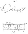
- FIG. 3 shows a top view of the distribution by zones of the heating means in the transverse direction.
- Figures 4 and 5 show a variant of the heating device in which heating means are offset and applied to both sides of a cover.
- FIG. 6 shows another variant of the heating device using here a hollow cylinder.
- Figure 1 shows part of a production line for double-sided corrugated cardboard (double-sided corrugator).
- the single-sided cover 1 from a coil 2 passes around a preheater cylinder 3 while being kept under tension by the tension rollers 4. It then undergoes differential heating in the transverse direction passing through the contact of a surface 5 of magnetic steel heated differently by electromagnetic induction. After passing around an assembly roller (smooth press) 6, it is assembled with the corrugated paper 7 previously heated by passing around the grooved preheater cylinder 8, and glued using a glue group 9.
- the sheet single-sided 10 is then driven by a belt 11 and various means 12 to a preheater cylinder 13 of this single-sided sheet 10 and then to a second sizing group 14 before being assembled with the double-sided cover 15.
- This double cover face 15 from a coil 16 passes around the preheater cylinder 17 and then in contact with a surface 18 of magnetic steel heated by induction, so as to conductively heat this cover 15 differentially in the transverse direction, before being assembled upstream of a first heating table 19 with the single-sided sheet 10.
- the double-sided sheet 20 then passes between the heating tables 19 arranged upstream of a tracer belt tion 21 and an upper belt 22 exerting pressure on said ply 20.
- FIG. 2 represents a differential heating zone in the cross direction, equipped with induction heating means, for example for the double-sided cover 15.
- These heating means are a magnetic steel plate heated by induction due to inductors 23 in disc shape in this example which are placed in a shoe 24 with a convex face formed by the plate 18 made of magnetic steel, and are arranged here as shown in Figure 3, along two lines in the cross direction.
- each inductor (or module) can be of the order of a few kW. This power naturally depends on the performance of the corrugator, its speed and its width.
- the cover 15 passes over the convex face 18 of the shoe 24 with a contact duration generally less than 1 second. This short duration is however sufficient to heat the roof in a differentiated manner and to ultimately reduce and eliminate the curl.
- the inductors can have various shapes chosen according to the area to be heated and the desired efficiency. They can be different from one sector to another.
- the inductors 27 may be arranged as shown in FIG. 4 and 5 in two successive shoes 25 and 26 with a convex face made of magnetic steel in contact with which the cover 1 or 15 to be heated passes, in the direction of the arrow by example.
- the inductors 27 (3 in number here) are shown staggered from one shoe to the other.
- the differential heating device is that described in connection with FIGS. 1, 2 and 3, equipped with 9 inductors, each of them showing a power which can vary between 0 and 5 kW.
- This device is connected to an operator console allowing the power of each inductor to be modulated.
- FIG. 6 shows a variant of an induction heating device for a paper cover.
- the inductors 28 are placed in a shoe 29 having a concave face 30 disposed opposite a hollow cylinder 31 made of magnetic steel in contact with which the cover 32 to be treated by differential heating passes, this cover passing between the cylinder and the face hoof concave.
- the cylinder 31 is disposed between the preheater cylinder and the heating tables (not shown).
- the length of contact of the cover with the cylinder which rotates at a linear speed equal to the speed of the paper depends on the diameter of the cylinder. In this example, it is 400 mm.
- the contact length which is the length of an arc of a circle also depends, of course, on the angle of this arc.
- the cylinder generally has a thickness of between 3 and 10 mm: the response time of the heating being the shorter the thickness of the cylinder is weak.
Landscapes
- Engineering & Computer Science (AREA)
- Mechanical Engineering (AREA)
- Machines For Manufacturing Corrugated Board In Mechanical Paper-Making Processes (AREA)
- General Induction Heating (AREA)
- Laminated Bodies (AREA)
- Shaping Of Tube Ends By Bending Or Straightening (AREA)
Abstract
Description
L'invention concerne la fabrication du carton ondulé, notamment du carton ondulé simple ou double face, et plus particulièrement un procédé et un dispositif pour réduire le tuilage du carton en fin d'onduleuse.The invention relates to the manufacture of corrugated cardboard, in particular single or double-sided corrugated cardboard, and more particularly a method and a device for reducing the curling of the cardboard at the end of the corrugator.
Le tuilage du carton est une déformation arrondie de la plaque de carton, provoquée par les allongements et retraits successifs que subissent les papiers lors des différentes phases de transformation sur une onduleuse.Cardboard curling is a rounded deformation of the cardboard sheet, caused by successive lengthening and shrinking that the papers undergo during the different transformation phases on a corrugator.
La plaque de carton en bout de ligne de fabrication peut présenter un tuilage dans le sens marche et/ou un tuilage dans le sens transversal.The cardboard plate at the end of the production line may have curling in the running direction and / or curling in the transverse direction.
Le tuilage dans le sens marche est généralement dû aux différences entre les tensions exercées sur les deux papiers couverture et il peut être assez facilement maîtrisé.The curl in the running direction is generally due to the differences between the tensions exerted on the two cover papers and it can be fairly easily controlled.
Le tuilage dans le sens transversal est généralement provoqué dans le cas d'un carton ondulé double face par la dilatation ou la contraction relative des couvertures dues à la différence de teneur en humidité entre les couvertures à l'endroit et au moment où se réalise l'assemblage de la nappe simple face et la couverture double face.Cross-curling is generally caused in the case of double-sided corrugated cardboard by the relative expansion or contraction of the covers due to the difference in moisture content between the covers at the place and at the time when they are made. assembly of the single-sided tablecloth and the double-sided cover.
Le tuilage transversal peut présenter une forme concave par rapport à sa face supérieure ou au contraire convexe ou encore en S.The transverse curl can have a concave shape relative to its upper face or on the contrary convex or even in S.
Les différences d'humidité entre les couvertures peuvent avoir plusieurs origines, parmi lesquelles on peut citer notamment la teneur en eau des papiers utilisés pour les couvertures, la teneur en eau des adhésifs, la dépose des adhésifs, les apports d'eau par les produits de traitement, l'efficacité des éléments chauffants tels que les préchauffeurs, les cylindres onduleurs, les plaques chauffantes, l'homogénéité de leur températures de surface, l'uniformité des efforts exercés par les organes de pressage, les cylindres onduleurs, les rouleaux applicateurs.The differences in humidity between the covers can have several origins, among which we can cite in particular the water content of the papers used for the covers, the water content of the adhesives, the removal of the adhesives, the water supplies by the treatment products, the efficiency of the heating elements such as the preheaters, the inverter cylinders, the heating plates, the homogeneity of their surface temperatures, the uniformity of the forces exerted by the pressing members, the inverter cylinders, the applicator rollers.
Le tuilage peut être détecté usuellement par le conducteur de la ligne de fabrication. Celui-ci dispose de deux moyens pour corriger les différences d'humidité : un premier moyen consistant à agir sur le séchage des couvertures en enveloppant plus ou moins les préchauffeurs à l'aide de rouleaux mobiles appelés rouleaux embarreurs ; un second moyen consistant à modifier les déposes de colle tout en conservant un bon collage.The curl can usually be detected by the operator of the production line. The latter has two means of correcting the differences in humidity: a first means consisting in acting on the drying of the blankets by more or less wrapping the preheaters using mobile rollers called bar feed rollers; a second means consisting in modifying the adhesive deposits while maintaining good bonding.
Ces moyens peuvent se révéler efficaces dans le cas de tuilages normal et inverse mais ne sont pas satisfaisants lorsqu'il s'agit de remédier à des tuilages complexes.These means can be effective in the case of normal and reverse tiling, but are not satisfactory when it comes to remedying complex tiling.
Pour remédier à ces tuilages complexes, on a déjà proposé d'utiliser des rampes de pulvérisation d'eau qui apporte un surplus d'eau aux parties de la laize présentant les teneurs en eau les plus faibles. Mais cette solution n'est pas entièrement satisfaisante car l'eau ajoutée augmente l'humidité globale du carton, ce qui entraîne d'autres inconvénients.To remedy these complex curlings, it has already been proposed to use water spraying ramps which provide excess water to the parts of the width having the lowest water contents. However, this solution is not entirely satisfactory since the added water increases the overall humidity of the carton, which leads to other drawbacks.
Pour remédier au lignage du papier dû à une distribution inégale de la teneur en eau sur différentes parties de la laize de papier, il a encore été proposé dans le document WO-A-8 705 062 de chauffer la laize de manière différenciée à l'aide de plaques chauffées à la vapeur ou électriquement. Cette solution n'est pas très satisfaisante.To remedy the lineage of the paper due to an uneven distribution of the water content on different parts of the paper web, it has also been proposed in document WO-A-8 705 062 to heat the web in a differentiated way with using steam or electrically heated plates. This solution is not very satisfactory.
Le chauffage à la vapeur ne présente pas une grande souplesse d'utilisation. La seule façon de moduler la température d'une plaque à l'autre consiste à introduire plus ou moins de vapeur dans ces plaques. Le réglage de la température est mal aisé et reste approximatif. En outre le temps de réponse est trop long.Steam heating is not very flexible in use. The only way to modulate the temperature from one plate to another is to introduce more or less steam into these plates. The temperature setting is difficult and remains approximate. In addition, the response time is too long.
Le chauffage électrique quant à lui présente également un temps de réponse beaucoup trop long. En outre ce type de chauffage est coûteux.Electric heating also has a response time that is far too long. Also this type of heating is expensive.
L'invention obvie aux inconvénients cités. Elle propose un procédé permettant de réduire le tuilage du carton ondulé et même de l'éliminer totalement lors de la fabrication d'une nappe continue de carton ondulé comportant au moins une cannelure et au moins une couverture, procédé souple et facile à mettre en oeuvre.The invention overcomes the disadvantages mentioned. It proposes a method making it possible to reduce the curl of corrugated cardboard and even to eliminate it completely during the manufacture of a continuous sheet of corrugated cardboard comprising at least one groove and at least one cover, a flexible and easy to implement method. .
Selon l'invention telle que définie principalement dans les revendications 1 et 7, on traite au moins une des couvertures du carton avant son assemblage avec la cannelure par au moins un chauffage inductif, différentiel dans le sens travers. De préférence, ce chauffage inductif et différentiel dans le sens travers est disposé entre un préchauffage de la couverture (cylindre à vapeur) et l'assemblage.According to the invention as defined mainly in
Par chauffage inductif on entend selon l'invention le chauffage à l'aide d'au moins un inducteur d'une surface en un matériau magnétique susceptible de chauffer par induction, au contact delaquelle passe la couverture qui est chauffée par conduction.By inductive heating is meant according to the invention heating with the aid of at least one inductor of a surface made of a magnetic material capable of heating by induction, in contact with which the cover passes which is heated by conduction.
Le chauffage inductif, différentiel dans le sens travers, permet selon l'invention de réguler la teneur en eau de la couverture et rendre cette teneur homogène sur toute la largeur de la laize. Par un chauffage différentiel selon l'emplacement désiré sur le travers on évitera finalement le phénomène de tuilage de la plaque de carton en bout de ligne. Le chauffage en étant inductif est très rapide, le temps de réponse étant quasi instantané. Il est très facilement modulable, il permet une meilleure homogénéité et répartition dans une zone donnée, il ne risque pas d'enflammer le papier.Inductive heating, differential in the cross direction, allows according to the invention to regulate the water content of the cover and make this content uniform over the entire width of the width. By differential heating depending on the desired location on the cross beam, we will ultimately avoid the phenomenon of cardboard plate curling at the end of the line. Heating by being inductive is very fast, the response time being almost instantaneous. It is very easily modular, it allows better homogeneity and distribution in a given area, it does not risk igniting the paper.
Selon une forme de réalisation du chauffage différentiel selon l'invention, ce chauffage peut être sectorisé, c'est-à-dire réparti sur le travers par secteur de chauffage et de non chauffage correspondant à des intervalles (ou zones) pouvant être égaux ou non, la puissance de chauffage pouvant préférentiellement être modulable et réglable dans chaque secteur de chauffage, la répartition par secteur présentant de préférence une symétrie par rapport à l'axe de la ligne de fabrication du carton ondulé.According to one embodiment of the differential heating according to the invention, this heating can be sectorized, that is to say distributed on the cross by heating and non-heating sector corresponding to intervals (or zones) which may be equal or no, the heating power can preferably be modular and adjustable in each heating sector, the distribution by sector preferably having symmetry with respect to the axis of the production line for corrugated cardboard.
Le nombre de secteurs de chauffage est au moins égal à 3 et de préférence au moins égal à 5.The number of heating sectors is at least equal to 3 and preferably at least equal to 5.
Les différents secteurs de chauffage pour une couverture peuvent être disposés sur une même ligne travers ou en variante sur au moins deux lignes travers en se répartissant en quinconce sur ces lignes. Ils peuvent être appliqués sur une ou les deux faces d'une couverture.The different heating sectors for a cover can be arranged on the same transverse line or alternatively on at least two transverse lines by distributing in staggered rows on these lines. They can be applied to one or both sides of a blanket.
Sous une forme préférée, le procédé selon l'invention est appliqué aux deux couvertures en papier avant leur assemblage avec la cannelure, lorsqu'il s'agit d'un carton ondulé double face.In a preferred form, the method according to the invention is applied to the two paper covers before their assembly with the groove, when it is a double-sided corrugated cardboard.
L'invention concerne également un dispositif pour la mise en oeuvre du procédé de chauffage différentiel d'au moins une couverture en vue de réduire et même supprimer le tuilage de la plaque de carton récupéré en bout de ligne de fabrication.The invention also relates to a device for implementing the differential heating process of at least one cover in order to reduce and even eliminate the curl of the cardboard plate recovered at the end of the production line.
Le dispositif selon l'invention comprend des moyens opérant un chauffage inductif et différentiel dans le sens travers d'au moins une couverture de carton, ces moyens étant disposés avant le poste d'assemblage de la couverture et de la cannelure, et de préférence entre le cylindre de préchauffage de la couverture et les tables chauffantes.The device according to the invention comprises means operating an inductive and differential heating in the transverse direction of at least one cardboard cover, these means being arranged before the station for assembling the cover and the groove, and preferably between the cover preheating cylinder and the heating tables.
Les moyens de chauffage inductif et différentiel sont sous une forme de réalisation du dispositif des moyens de chauffage sectorisé, c'est-à-dire des moyens agissant sur des zones déterminées du sens travers.The inductive and differential heating means are in one embodiment of the device of the sectorized heating means, that is to say means acting on determined zones in the cross direction.
Ces moyens de chauffage sont selon une réalisation préférée du dispositif des inducteurs disposés selon au moins une ligne dans le sens travers, agissant sur une surface en un matériau magnétique susceptible de chauffer par induction. Pour obtenir un temps de réponse très court, la surface en un matériau magnétique, par exemple en acier magnétique, chauffée par induction présente de préférence une épaisseur la plus réduite possible, la limite étant la résistance mécanique nécessaire. Cette épaisseur peut-être comprise entre 0,5 et 5 mm par exemple.These heating means are, according to a preferred embodiment of the device, of the inductors arranged in at least one line in the cross direction, acting on a surface made of a magnetic material capable of heating by induction. To obtain a very short response time, the surface made of a magnetic material, for example magnetic steel, heated by induction preferably has a thickness as small as possible, the limit being the necessary mechanical resistance. This thickness may be between 0.5 and 5 mm for example.
Dans une forme de réalisation de l'invention, les inducteurs peuvent être placés dans un sabot à surface convexe, au contact de laquelle passe la couverture à chauffer différentiellement. Le matériau dont est constitué la surface convexe est un matériau magnétique, notamment de l'acier magnétique qui se présente en forme de feuille de faible épaisseur.In one embodiment of the invention, the inductors can be placed in a shoe with a convex surface, in contact with which passes the blanket to be differentially heated. The material of which the convex surface is a magnetic material, in particular magnetic steel which is in the form of a thin sheet.
Dans une forme de réalisation préférée de l'invention, on fait passer la couverture en papier autour d'un cylindre creux en un matériau magnétique, notamment en acier magnétique, chauffé par induction due à des inducteurs disposés à proximité de sa périphérie.In a preferred embodiment of the invention, the paper cover is passed around a hollow cylinder made of a magnetic material, in particular magnetic steel, heated by induction due to inductors arranged near its periphery.
En utilisant un cylindre creux d'un diamètre convenable, généralement supérieur à 200 mm, on peut ainsi obtenir la longueur de contact entre la couverture et le cylindre chauffé différenciellement plus importante que la longueur de contact au passage d'un sabot, ceci pour une surface d'inducteur donnée. La longueur de contact dépend du diamètre du cylindre mais aussi bien évidemment de la longueur de l'arc de contact pour un diamètre donné. Cette longueur de l'arc peut en outre être avantageusement modifiée par un réglage de la position des rouleaux dits d'embarrage.By using a hollow cylinder of a suitable diameter, generally greater than 200 mm, it is thus possible to obtain the contact length between the cover and the heated cylinder which is differentially greater than the contact length when a shoe passes, this for a given inductor area. The contact length depends on the diameter of the cylinder but also obviously on the length of the contact arc for a given diameter. This length of the arch can also be advantageously modified by adjusting the position of the so-called tying rollers.
Le cylindre est creux et sa paroi destinée a être chauffée par induction est de préférence peu épaisse afin de réduire le temps de réponse. Cette épaisseur dépend de la résistance mécanique nécessaire à l'application. Elle est généralement comprise entre 2 et 10 mm.The cylinder is hollow and its wall intended to be heated by induction is preferably not very thick in order to reduce the response time. This thickness depends on the mechanical resistance necessary for the application. It is generally between 2 and 10 mm.
D'autres avantages et caractéristiques de l'invention apparaîtront dans la suite de la description d'exemples de réalisation de l'invention, faite en référence aux figures.Other advantages and characteristics of the invention will appear in the following description of the embodiments of the invention, given with reference to the figures.
La figure 1 représente schématiquement une partie d'une ligne de fabrication d'un carton ondulé double face, équipée d'un dispositif de chauffage différentiel selon l'invention.FIG. 1 schematically represents part of a production line for a double-sided corrugated cardboard, equipped with a differential heating device according to the invention.
La figure 2 représente schématiquement le dispositif de chauffage différentiel de la figure 1 agissant sur une couverture.Figure 2 schematically shows the differential heating device of Figure 1 acting on a blanket.
La figure 3 représente en vue de dessus la répartition par zones des moyens de chauffage dans le sens travers.FIG. 3 shows a top view of the distribution by zones of the heating means in the transverse direction.
Les figures 4 et 5 représentent une variante du dispositif de chauffage dans laquelle des moyens de chauffage sont décalés et appliqués sur les deux faces d'une couverture.Figures 4 and 5 show a variant of the heating device in which heating means are offset and applied to both sides of a cover.
La figure 6 représente une autre variante du dispositif de chauffage utilisant ici un cylindre creux.FIG. 6 shows another variant of the heating device using here a hollow cylinder.
La figure 1 représente une partie d'une ligne de fabrication d'un carton ondulé double face (onduleuse double face).Figure 1 shows part of a production line for double-sided corrugated cardboard (double-sided corrugator).
Dans cette ligne de fabrication, la couverture simple face 1 issue d'une bobine 2 passe autour d'un cylindre préchauffeur 3 en étant maintenue sous tension par les rouleaux de tension 4. Elle subit ensuite un chauffage différentiel dans le sens travers en passant au contact d'une surface 5 en acier magnétique chauffée de façon différentielle par induction électromagnétique. Après passage autour d'un rouleau d'assemblage (presse lisse) 6, elle est assemblée avec le papier cannelure 7 préalablement réchauffé par passage autour du cylindre préchauffeur cannelé 8, et encollé à l'aide d'un groupe encolleur 9. La nappe simple face 10 est ensuite entrainée par une courroie 11 et différents moyens 12 jusqu'à un cylindre préchauffeur 13 de cette nappe simple face 10 et ensuite à un second groupe encolleur 14 avant d'être assemblée avec la couverture double face 15. Cette couverture double face 15 issue d'une bobine 16 passe autour du cylindre préchauffeur 17 puis au contact d'une surface 18 en acier magnétique chauffée par induction, de façon à chauffer par conduction cette couverture 15 de façon différentielle dans le sens travers, avant d'être assemblée en amont d'une première table chauffante 19 avec la nappe simple face 10. La nappe double face 20 passe ensuite entre les tables chauffantes 19 disposées en amont d'une courroie de traction 21 et une courroie supérieure 22 exerçant une pression sur ladite nappe 20.In this production line, the single-sided cover 1 from a coil 2 passes around a
La figure 2 représente une zone de chauffage différentiel dans le sens travers, équipée des moyens de chauffage par induction, par exemple pour la couverture double face 15. Ces moyens de chauffage sont une plaque en acier magnétique chauffée par induction due à des inducteurs 23 en forme de disque dans cet exemple qui sont placés dans un sabot 24 à face convexe formée de la plaque 18 en acier magnétique, et sont disposés ici comme représenté sur la figure 3, suivant deux lignes dans le sens travers.FIG. 2 represents a differential heating zone in the cross direction, equipped with induction heating means, for example for the double-sided
Dans cet exemple les inducteurs 23 sont au nombre de 9. La puissance maximum consommée par chaque inducteur (ou module) peut être de l'ordre de quelques kW. Cette puissance dépend bien entendu des performances de l'onduleuse, sa vitesse et sa laize.In this example, there are 9
La couverture 15 passe sur la face convexe 18 du sabot 24 avec une durée de contact généralement inférieure à 1 seconde. Cette faible durée est cependant suffisante pour chauffer de façon différenciée la couverture et pour finalement réduire et éliminer le tuilage.The
Les inducteurs peuvent avoir des formes diverses choisies selon la zone à chauffer et l'efficacité souhaitée. Ils peuvent être différents d'un secteur à l'autre.The inductors can have various shapes chosen according to the area to be heated and the desired efficiency. They can be different from one sector to another.
Dans une variante les inducteurs 27 peuvent être disposés comme représentés dans la figure 4 et 5 dans deux sabots successifs 25 et 26 à face convexe en acier magnétique au contact de laquelle passe la couverture 1 ou 15 à chauffer, dans le sens selon la flèche par exemple. Les inducteurs 27 (au nombre de 3 ici) sont représentés disposés en quinconce d'un sabot à l'autre.In a variant, the
Par la suite nous décrivons un exemple de fabrication d'un carton double face avec traitement par chauffage différentiel dans le sens travers de la couverture double face du carton.Subsequently we describe an example of manufacturing a double-sided cardboard with differential heating treatment in the cross direction of the double-sided cover of the cardboard.
Le dispositif de chauffage différentiel est celui décrit en relation avec les figures 1, 2 et 3, équipé de 9 inducteurs, chacun d'eux montrant une puissance pouvant varier entre 0 et 5 kW. Ce dispositif est relié à une console opérateur permettant de moduler la puissance de chaque inducteur.The differential heating device is that described in connection with FIGS. 1, 2 and 3, equipped with 9 inductors, each of them showing a power which can vary between 0 and 5 kW. This device is connected to an operator console allowing the power of each inductor to be modulated.
En cours de fabrication, l'opérateur est amené à utiliser le chauffage différentiel dès lors qu'un tuilage apparaît sur la plaque de carton en bout de ligne.During manufacture, the operator is led to use differential heating as soon as a curl appears on the cardboard plate at the end of the line.
En augmentant ou en diminuant la puissance de chauffage, séparément pour chaque inducteur, il procure aux surfaces de contact avec la couverture et donc à la couverture, d'une façon précise dans le sens travers, les températures idéales pour réduire et annuler le tuilage du carton.By increasing or decreasing the heating power, separately for each inductor, it provides the contact surfaces with the cover and therefore the cover, precisely in a cross direction, the ideal temperatures to reduce and cancel the curling of the cardboard.
Sur la figure 6, on a représenté une variante d'un dispositif de chauffage par induction d'une couverture en papier.FIG. 6 shows a variant of an induction heating device for a paper cover.
Dans cette variante, les inducteurs 28 sont placés dans un sabot 29 présentant une face concave 30 disposée face à un cylindre creux 31 en acier magnétique au contact duquel défile la couverture 32 à traiter par chauffage différentiel , cette couverture passant entre le cylindre et la face concave du sabot. Le cylindre 31 est disposé entre le cylindre préchauffeur et les tables chauffantes (non représentés).In this variant, the
La longueur de contact de la couverture avec le cylindre qui tourne à une vitesse linéaire égale à la vitesse du papier, dépend du diamètre du cylindre. Dans cet exemple, il est de 400 mm. La longueur de contact qui est la longueur d'un arc de cercle dépend aussi, évidemment, de l'angle de cet arc.The length of contact of the cover with the cylinder which rotates at a linear speed equal to the speed of the paper, depends on the diameter of the cylinder. In this example, it is 400 mm. The contact length which is the length of an arc of a circle also depends, of course, on the angle of this arc.
Cet angle peut avantageusement être réglé en modifiant la position des deux rouleaux d'embarrage 33, 34. Le cylindre présente une épaisseur comprise généralement entre 3 et 10 mm : le temps de réponse du chauffage étant d'autant plus court que l'épaisseur du cylindre est faible.This angle can advantageously be adjusted by modifying the position of the two tying
Claims (19)
- Method of reducing the curving of corrugated cardboard during the production of a continuous band of corrugated cardboard comprising at least one corrugated sheet and at least one cover sheet, characterized in that at least one cover sheet of the cardboard is treated by at least one inductive heating, differential in the transverse direction, of a surface of a magnetic material, in contact with which the cover sheet passes, before it is assembled together with a corrugated sheet.
- Method according to claim 1, characterized in that the differential heating is divided by sectors.
- Method according to one of claims 1 to 2, characterized in that the number of sectors is at least 3 and preferably at least 5.
- Method according to one of claims 1 to 3, characterized in that the differential heating of the cover sheet is disposed between the preheating of the cover sheet and its assembly with the corrugated sheet.
- Method according to one of claims 1 to 4, characterized in that the two cover sheets of a double-faced corrugated cardboard are treated by a differential heating.
- Method according to one of claims 1 to 5, characterized in that the heated surface is the surface of a cylinder which revolves at a linear speed equal to that of the cover sheet.
- Device for carrying out the method according to one of claims 1 to 6, characterized in that it comprises means (5, 18) for induction heating operating a differential heating in the transverse direction of at least one surface of a heatable magnetic material, in contact with which at least one cover sheet (1, 15) of the cardboard passes, before its assembly with a corrugated sheet.
- Device according to claim 7, characterized in that the differential heating means (5, 18) are disposed between a preheating cylinder (3, 17) for the cover sheet and heating tables (19).
- Device according to one of claims 7 or 8, characterized in that the means operating a differential heating act by sectors, each heating sector being provided with at least one inductor.
- Device according to claim 9, characterized in that the inductors are disposed in at least one shoe (24, 25, 26) having a convex face formed of a magnetic steel plate in contact with which the cover sheet of the corrugated cardboard to be treated passes.
- Device according to claim 10, characterized in that the inductors are disposed in staggered arrangement.
- Device according to claim 11, characterized in that the inductors are disposed in staggered arrangement in two successive shoes with convex face arranged head-to-tail.
- Device according to one of claims 10 to 12, characterized in that the inductors have a shape capable of following the convex shape of the shoe.
- Device according to claims 7 to 9, characterized in that the surface of a magnetic material is a cylindrical surface.
- Device according to claim 14, characterized in that the inductors are placed in at least one shoe having a concave face disposed opposite the cylinder of a magnetic material, notably of magnetic steel.
- Device according to one of claims 14 or 15, characterized in that the cylinder is hollow and that the thickness of its wall is from 2 to 10 mm.
- Device according to one of claims 14 to 16, characterized in that the cylinder revolves at a linear speed equal to that of the cover sheet.
- Device according to one of claims 14 to 17, characterized in that lifting rollers (33, 34) regulate the contact length between the cover sheet (32) and the cylinder (31).
- Device according to one of claims 7 to 18, characterized in that it forms part of a production line for double-faced corrugated cardboard and that it comprises differential heating means for both the cover sheets of the corrugated cardboard.
Applications Claiming Priority (2)
| Application Number | Priority Date | Filing Date | Title |
|---|---|---|---|
| FR9212895A FR2697201B1 (en) | 1992-10-28 | 1992-10-28 | Method and device for manufacturing corrugated cardboard. |
| FR9212895 | 1992-10-28 |
Publications (2)
| Publication Number | Publication Date |
|---|---|
| EP0595711A1 EP0595711A1 (en) | 1994-05-04 |
| EP0595711B1 true EP0595711B1 (en) | 1996-12-18 |
Family
ID=9434950
Family Applications (1)
| Application Number | Title | Priority Date | Filing Date |
|---|---|---|---|
| EP93402626A Expired - Lifetime EP0595711B1 (en) | 1992-10-28 | 1993-10-26 | Method and apparatus for the manufacture of corrugated cardboard |
Country Status (6)
| Country | Link |
|---|---|
| EP (1) | EP0595711B1 (en) |
| AT (1) | ATE146398T1 (en) |
| DE (1) | DE69306734T2 (en) |
| DK (1) | DK0595711T3 (en) |
| ES (1) | ES2096889T3 (en) |
| FR (1) | FR2697201B1 (en) |
Families Citing this family (2)
| Publication number | Priority date | Publication date | Assignee | Title |
|---|---|---|---|---|
| DE19506778A1 (en) * | 1995-02-27 | 1996-08-29 | Bhs Corr Masch & Anlagenbau | Process for the production of corrugated cardboard |
| DE19716706A1 (en) * | 1997-04-21 | 1998-10-29 | Bhs Corr Masch & Anlagenbau | Machine for producing corrugated cardboard length coated on one side |
Family Cites Families (4)
| Publication number | Priority date | Publication date | Assignee | Title |
|---|---|---|---|---|
| US3340125A (en) * | 1964-12-18 | 1967-09-05 | Koppers Co Inc | Adhesive bonding method and apparatus |
| DE3400333C2 (en) * | 1983-08-19 | 1986-08-21 | Werner H.K. Peters Maschinenfabrik Gmbh, 2000 Hamburg | Heating device for corrugated cardboard in a corrugated cardboard gluing machine |
| NL8600454A (en) * | 1986-02-24 | 1987-09-16 | Cornelis Hendrikus Alsema | HEATING DEVICE FOR RUNNING JOBS PAPER WITH SECTION-CONTROLLED ADJUSTABLE HEAT SUPPLY. |
| AU653431B2 (en) * | 1991-08-19 | 1994-09-29 | Amcor Limited | panufacturing corrugated board |
-
1992
- 1992-10-28 FR FR9212895A patent/FR2697201B1/en not_active Expired - Fee Related
-
1993
- 1993-10-26 AT AT93402626T patent/ATE146398T1/en active
- 1993-10-26 EP EP93402626A patent/EP0595711B1/en not_active Expired - Lifetime
- 1993-10-26 DK DK93402626.1T patent/DK0595711T3/en active
- 1993-10-26 ES ES93402626T patent/ES2096889T3/en not_active Expired - Lifetime
- 1993-10-26 DE DE69306734T patent/DE69306734T2/en not_active Expired - Lifetime
Also Published As
| Publication number | Publication date |
|---|---|
| DK0595711T3 (en) | 1997-06-02 |
| DE69306734T2 (en) | 1997-07-10 |
| DE69306734D1 (en) | 1997-01-30 |
| EP0595711A1 (en) | 1994-05-04 |
| ES2096889T3 (en) | 1997-03-16 |
| FR2697201A1 (en) | 1994-04-29 |
| FR2697201B1 (en) | 1994-12-16 |
| ATE146398T1 (en) | 1997-01-15 |
Similar Documents
| Publication | Publication Date | Title |
|---|---|---|
| FR2739319A1 (en) | MACHINE FOR MANUFACTURING A CURVED CARTON STRIP, DOUBLED AT LEAST ON ONE SIDE | |
| EP0485731B1 (en) | Assembly device for machine for the production of corrugated cardboard | |
| EP0572503B1 (en) | Paper sheets having several distinct layers with markings and process for producing them | |
| EP0426548A1 (en) | Multi-ply sheet of absorbent paper | |
| EP0662045B1 (en) | Machine and method for making a sheet of single face corrugated cardboard | |
| ES2091343T3 (en) | METHOD AND DEVICE FOR WRAPPING ROLLS, IN PARTICULAR PAPER ROLLS, IN A WRAPPING SHEET. | |
| FR2576493A1 (en) | METHOD AND APPARATUS FOR GLUING TEXTILE PANELS | |
| EP0595711B1 (en) | Method and apparatus for the manufacture of corrugated cardboard | |
| KR19980041992A (en) | Improved low pressure single phaser | |
| EP0758295B1 (en) | Machine and method of manufacture of single-face corrugated board by traction glueing | |
| US5600900A (en) | Vacuum assisted web drying system | |
| KR19990078044A (en) | Single facer with small intermediate corrugating roll and variable wrap arm device | |
| US5766410A (en) | Corrugating machine with an elastic press plate | |
| FR2570327A1 (en) | APPARATUS FOR SINGING ONDULATIONS OF A CORRUGATED CARDBOARD, AND METHOD FOR MANUFACTURING MULTILAYER COMPOSITE ELEMENTS | |
| EP0794050B1 (en) | Corrugated packaging material and machine and process for the manufacture of corrugated packaging material | |
| EP0901898B1 (en) | Device as well as process for the manufacture of corrugated paper | |
| FR2761636A1 (en) | Folding-groove applying machine used for applying folding grooves to corrugated boards | |
| JP2000071356A (en) | Production and device for embossing laminated paper | |
| EP0153220A2 (en) | Machine for heat sealing webs or films onto a flexible or rigid support | |
| FR2719254A1 (en) | Continuous band press. | |
| FR2654024A1 (en) | IMPROVEMENTS TO TAPE SLITTING FACILITIES. | |
| FR2751584A1 (en) | MACHINE AND METHOD FOR MANUFACTURING SINGLE-SIDE WAVE CARDBOARD SHEET WITH UPSTREAM TRACTION | |
| KR200211769Y1 (en) | Apparatus for preheating a bonding agent or an edge band of an edge banding machine | |
| FR2753996A1 (en) | Transparent synthetic materials used as flat sheets or wound rolls | |
| JPS6058020B2 (en) | How to process embossed paper |
Legal Events
| Date | Code | Title | Description |
|---|---|---|---|
| PUAI | Public reference made under article 153(3) epc to a published international application that has entered the european phase |
Free format text: ORIGINAL CODE: 0009012 |
|
| AK | Designated contracting states |
Kind code of ref document: A1 Designated state(s): AT BE CH DE DK ES FR GB IT LI NL PT SE |
|
| 17P | Request for examination filed |
Effective date: 19941028 |
|
| GRAG | Despatch of communication of intention to grant |
Free format text: ORIGINAL CODE: EPIDOS AGRA |
|
| 17Q | First examination report despatched |
Effective date: 19960205 |
|
| GRAH | Despatch of communication of intention to grant a patent |
Free format text: ORIGINAL CODE: EPIDOS IGRA |
|
| GRAH | Despatch of communication of intention to grant a patent |
Free format text: ORIGINAL CODE: EPIDOS IGRA |
|
| RAP1 | Party data changed (applicant data changed or rights of an application transferred) |
Owner name: SMURFIT WORLDWIDE RESEARCH EUROPE |
|
| GRAA | (expected) grant |
Free format text: ORIGINAL CODE: 0009210 |
|
| AK | Designated contracting states |
Kind code of ref document: B1 Designated state(s): AT BE CH DE DK ES FR GB IT LI NL PT SE |
|
| REF | Corresponds to: |
Ref document number: 146398 Country of ref document: AT Date of ref document: 19970115 Kind code of ref document: T |
|
| REF | Corresponds to: |
Ref document number: 69306734 Country of ref document: DE Date of ref document: 19970130 |
|
| REG | Reference to a national code |
Ref country code: CH Ref legal event code: NV Representative=s name: KIRKER & CIE SA |
|
| ITF | It: translation for a ep patent filed | ||
| REG | Reference to a national code |
Ref country code: ES Ref legal event code: FG2A Ref document number: 2096889 Country of ref document: ES Kind code of ref document: T3 |
|
| GBT | Gb: translation of ep patent filed (gb section 77(6)(a)/1977) |
Effective date: 19970227 |
|
| REG | Reference to a national code |
Ref country code: DK Ref legal event code: T3 |
|
| REG | Reference to a national code |
Ref country code: PT Ref legal event code: SC4A Free format text: AVAILABILITY OF NATIONAL TRANSLATION Effective date: 19970314 |
|
| PGFP | Annual fee paid to national office [announced via postgrant information from national office to epo] |
Ref country code: DK Payment date: 19970807 Year of fee payment: 5 |
|
| PLBE | No opposition filed within time limit |
Free format text: ORIGINAL CODE: 0009261 |
|
| STAA | Information on the status of an ep patent application or granted ep patent |
Free format text: STATUS: NO OPPOSITION FILED WITHIN TIME LIMIT |
|
| 26N | No opposition filed | ||
| PG25 | Lapsed in a contracting state [announced via postgrant information from national office to epo] |
Ref country code: DK Free format text: LAPSE BECAUSE OF NON-PAYMENT OF DUE FEES Effective date: 19981026 |
|
| REG | Reference to a national code |
Ref country code: GB Ref legal event code: IF02 |
|
| REG | Reference to a national code |
Ref country code: DK Ref legal event code: EBP |
|
| PGFP | Annual fee paid to national office [announced via postgrant information from national office to epo] |
Ref country code: FR Payment date: 20121122 Year of fee payment: 20 Ref country code: CH Payment date: 20121012 Year of fee payment: 20 Ref country code: DE Payment date: 20121024 Year of fee payment: 20 Ref country code: BE Payment date: 20121025 Year of fee payment: 20 |
|
| PGFP | Annual fee paid to national office [announced via postgrant information from national office to epo] |
Ref country code: ES Payment date: 20121031 Year of fee payment: 20 Ref country code: PT Payment date: 20120426 Year of fee payment: 20 Ref country code: GB Payment date: 20121024 Year of fee payment: 20 Ref country code: IT Payment date: 20121013 Year of fee payment: 20 Ref country code: SE Payment date: 20121011 Year of fee payment: 20 |
|
| PGFP | Annual fee paid to national office [announced via postgrant information from national office to epo] |
Ref country code: AT Payment date: 20120927 Year of fee payment: 20 Ref country code: NL Payment date: 20121010 Year of fee payment: 20 |
|
| REG | Reference to a national code |
Ref country code: DE Ref legal event code: R071 Ref document number: 69306734 Country of ref document: DE |
|
| BE20 | Be: patent expired |
Owner name: *SMURFIT WORLDWIDE RESEARCH EUROPE Effective date: 20131026 |
|
| REG | Reference to a national code |
Ref country code: CH Ref legal event code: PL |
|
| REG | Reference to a national code |
Ref country code: NL Ref legal event code: V4 Effective date: 20131026 Ref country code: PT Ref legal event code: MM4A Free format text: MAXIMUM VALIDITY LIMIT REACHED Effective date: 20131026 |
|
| REG | Reference to a national code |
Ref country code: GB Ref legal event code: PE20 Expiry date: 20131025 |
|
| REG | Reference to a national code |
Ref country code: SE Ref legal event code: EUG |
|
| REG | Reference to a national code |
Ref country code: AT Ref legal event code: MK07 Ref document number: 146398 Country of ref document: AT Kind code of ref document: T Effective date: 20131026 |
|
| PG25 | Lapsed in a contracting state [announced via postgrant information from national office to epo] |
Ref country code: PT Free format text: LAPSE BECAUSE OF EXPIRATION OF PROTECTION Effective date: 20131106 Ref country code: DE Free format text: LAPSE BECAUSE OF EXPIRATION OF PROTECTION Effective date: 20131029 Ref country code: GB Free format text: LAPSE BECAUSE OF EXPIRATION OF PROTECTION Effective date: 20131025 |
|
| REG | Reference to a national code |
Ref country code: ES Ref legal event code: FD2A Effective date: 20140925 |
|
| PG25 | Lapsed in a contracting state [announced via postgrant information from national office to epo] |
Ref country code: ES Free format text: LAPSE BECAUSE OF EXPIRATION OF PROTECTION Effective date: 20131027 |