EP0594545A1 - Motorized concealable sliding door having an improved box - Google Patents
Motorized concealable sliding door having an improved box Download PDFInfo
- Publication number
- EP0594545A1 EP0594545A1 EP93830367A EP93830367A EP0594545A1 EP 0594545 A1 EP0594545 A1 EP 0594545A1 EP 93830367 A EP93830367 A EP 93830367A EP 93830367 A EP93830367 A EP 93830367A EP 0594545 A1 EP0594545 A1 EP 0594545A1
- Authority
- EP
- European Patent Office
- Prior art keywords
- door
- box
- motorized
- sliding door
- sliding
- Prior art date
- Legal status (The legal status is an assumption and is not a legal conclusion. Google has not performed a legal analysis and makes no representation as to the accuracy of the status listed.)
- Granted
Links
Images


Classifications
-
- E—FIXED CONSTRUCTIONS
- E06—DOORS, WINDOWS, SHUTTERS, OR ROLLER BLINDS IN GENERAL; LADDERS
- E06B—FIXED OR MOVABLE CLOSURES FOR OPENINGS IN BUILDINGS, VEHICLES, FENCES OR LIKE ENCLOSURES IN GENERAL, e.g. DOORS, WINDOWS, BLINDS, GATES
- E06B3/00—Window sashes, door leaves, or like elements for closing wall or like openings; Layout of fixed or moving closures, e.g. windows in wall or like openings; Features of rigidly-mounted outer frames relating to the mounting of wing frames
- E06B3/32—Arrangements of wings characterised by the manner of movement; Arrangements of movable wings in openings; Features of wings or frames relating solely to the manner of movement of the wing
- E06B3/34—Arrangements of wings characterised by the manner of movement; Arrangements of movable wings in openings; Features of wings or frames relating solely to the manner of movement of the wing with only one kind of movement
- E06B3/42—Sliding wings; Details of frames with respect to guiding
- E06B3/46—Horizontally-sliding wings
- E06B3/4654—Horizontally-sliding wings disappearing in pockets in the wall; Pockets therefor
Definitions
- the present invention relates to a motorized concealable sliding door, having an improved box.
- the box in particular, is made of galvanized sheet metal elements which are damaged in those regions thereof where is performed a high temperature welding operation, that is that type of welding process which must be necessarily used for coupling the grating net to the box.
- the aim of the present invention is to overcome the above mentioned drawbacks, by providing a motorized concealable sliding door including an improved box, in which there are completely eliminated the welded regions necessary for connecting the grating net and the box strip elements, so that the sliding door can be advantageously used mainly in outside applications.
- a main object of the present invention is to provide such a motorized sliding door, which allows to house its driving motor in a very compact manner, so as to prevent projecting regions from being generated with respect to the wall, thereby allowing the wall to be exploited for other applications.
- Another object of the present invention is to provide such a door construction in which the rails,togetherwith the driving members, can be reassembled outside of the door box and then can be mounted by a quick connection system on the top cross member of the door.
- Yet another object of the present invention is to provide such a sliding door which is very reliable and safe in operation.
- a motorized concealable sliding door having an improved box, comprising a frame defining sliding rails for at least a door wing, and a box, suitable to be housed inside a wall, characterized in that on the major faces of said box, formed by fretted and galvanized strip like elements, there are provided grating elements which are connected by connecting clips suitable to mechanically connect said strip elements and box.
- the motorizing concealable sliding door provided with an improved door box according to the present invention, which has been generally indicated at the reference number 1, comprises a door frame 2, which is advantageously made of suitably contoured sheet metal section members and which defines a door box 3 arranged adjoining the opening port of the door.
- This box in particular, is made of fretted strip like elements 4 which are slidably connected to one another and caulked so as to mutually lock these elements.
- the strip elements are connected by a bottom strip element 5 closing at the end the door box.
- the door box is made of galvanized fretted strip like elements and, heretofore, it was very difficult to connect to the door box the grating net 10 which is conventionally used for coupling the wall finishing plastering applied on the wall in which the door box is usually housed.
- a main feature of the present invention is that the grating net 10 is connected by clips 11 which are engaged on strip-like elements and suitably bent so as to provide a mechanical type of connection, which does not damage the galvanized protection.
- thermally insulated layers 12 Inside the door box there are provided thermally insulated layers 12, providing a very good thermal insulation and barrier against heat losses.
- motorizing or driving means comprising an electric motor 20 which is connected to the top cross-member of the doorframe and is arranged at an intermediate portion of the door.
- the electric motor 20 through a bevel gear pair 21, drives a toothed pulley 22, entraining a toothed belt, indicated at the reference number 23, connected to one of the truck assemblies 24 supporting the door.
- the toothed belt 23 is further entrained on a transmissione toothed pulley 25, arranged near the rabbet of the door and also supported by the top cross-member.
- the truck assemblies 24 can slide on rails 25 having a C-shape and also connected to the top cross-member 26 of the door frame.
- a wing indicated at the reference number 30, which, owing to the very good strength of this construction, can also have a comparatively great weight.
- the motor further comprises a coaxial-axis motor reducing unit, which allows the possibility of manually opening the door in case of power failure or other emergency cases.
- a guide vertical section member 31 of omega shape inside which can slide a small bolt 32, comprising a bolt rod including a contoured elongated slot 33, engaging with a locking pin element 34 provided on the door rabbet.
- the bolt 32 is provided with a bolt block 35, having a recess 36 in which can be engaged the head portion 37 of a rod 38 connected to an electromagnet 39 which will drive the bolt 32 from its locking position to its releasing position and vice versa.
- the electromagnet is housed in the fixed door part and will cause the contoured head 37 to be engaged in the seat 36, as the door wing 30 is closed, and then it will allow the subsequent translating motion providing the locking of the door.
- a manual unlocking lever indicated at the reference numer 40, which directly operates on the electromagnet.
- the electric motor is so arranged that it allows to reduce to a minimum the occupied space, and moreover provides a very improved operation.
- the used material, as well as the contigent size and shape can be according to requirements.
Landscapes
- Engineering & Computer Science (AREA)
- Civil Engineering (AREA)
- Structural Engineering (AREA)
- Power-Operated Mechanisms For Wings (AREA)
- Support Devices For Sliding Doors (AREA)
- Special Wing (AREA)
- Lock And Its Accessories (AREA)
- Refrigerator Housings (AREA)
- Housing For Livestock And Birds (AREA)
Abstract
Description
- The present invention relates to a motorized concealable sliding door, having an improved box.
- As is known, there are already commercially available concealable sliding doors to be used both for outside and inside environments, which are provided with a door frame defining a box which is made of fretted strip elements which are connected to one another so as to provide the construction to be introduced into the wall.
- In order to facilitate the coupling of the box covering plastering, it is necessary to apply a grating net or the like, extending through the two major faces of the box.
- The box, in particular, is made of galvanized sheet metal elements which are damaged in those regions thereof where is performed a high temperature welding operation, that is that type of welding process which must be necessarily used for coupling the grating net to the box.
- Under these conditions there are generated spots where the galvanized protection is lacking and at these spots, the assembled metal parts can be easily subjected to rust.
- Another problem is that prior solutions are affected by great difficulties, in particular with respect to the application of a driving assembly, since they require a rather complex installation operation with consequent large size and projection of the door from the wall, thereby the wall housing the door can not be practically further exploited.
- Another drawback of prior solutions is that prior sliding doors of the above mentioned type are scarcely flexible in operation and, moreover, they do not afford the possibility of making a double sliding door, since the prior constructions are not suitable to provide the necessary width for a double sliding door.
- Yet another problem, moreover, is that of a poor thermal insulation of prior sliding doors, with consequent great thermal loss spots through the door.
- Accordingly, the aim of the present invention is to overcome the above mentioned drawbacks, by providing a motorized concealable sliding door including an improved box, in which there are completely eliminated the welded regions necessary for connecting the grating net and the box strip elements, so that the sliding door can be advantageously used mainly in outside applications.
- Within the scope of the above mentioned aim, a main object of the present invention is to provide such a motorized sliding door, which allows to house its driving motor in a very compact manner, so as to prevent projecting regions from being generated with respect to the wall, thereby allowing the wall to be exploited for other applications.
- Another object of the present invention is to provide such a door construction in which the rails,togetherwith the driving members, can be reassembled outside of the door box and then can be mounted by a quick connection system on the top cross member of the door.
- Yet another object of the present invention is to provide such a sliding door which is very reliable and safe in operation.
- According to one aspect of the present invention, the above mentioned aim and objects, as well as yet other objects, which will become more apparent hereinafter, are achieved by a motorized concealable sliding door, having an improved box, comprising a frame defining sliding rails for at least a door wing, and a box, suitable to be housed inside a wall, characterized in that on the major faces of said box, formed by fretted and galvanized strip like elements, there are provided grating elements which are connected by connecting clips suitable to mechanically connect said strip elements and box.
- Further characteristics and advantages of the present invention will become more apparent hereinafter from the following description of a preferred, though not exclusive, embodiment of a motorized concealable sliding door provided with an improved box, which is illustrated, by way of an indicative but not limitative example, in the accompanying drawings, where:
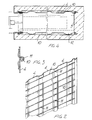
- Figure 1 is a schematic elevation view illustrating the motorized sliding door according to the invention, and in which there is clearly also shown the door box;
- Figure 2 shows a major or main wall or panel of the box, to which there is applied a grating net;
- Figure 3 is a schematic cross-sectional view illustrating the connection between the grating net and box;
- Figure 4 is a horizontal cross-sectional view illustrating the box with the grating net and thermally insulating layers;
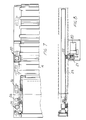
- Figure 5 is a schematic top-plane and cross-sectional horizontal view of the sliding door according to the present invention;
- Figure 6 is a cross-sectional view illustrating the top sliding guides of the door;
- Figure 7 is an elevation view illustrating the driving means for driving the sliding door;
- Figure 8 is a top plane view of the subject driving means.
- Figure 9 illustrates a motor-reducing unit for manually driving the door;
- Figure 10 is a cross-sectional view illustrating the electric closure door bolt;
- Figure 11 is a perspective view of the door bolts; and
- Figure 12 is a vertical cross-sectional view illustrating a sliding door provided with a double sliding door wing.
- With reference to the number references of the above disclosed figures, the motorizing concealable sliding door provided with an improved door box according to the present invention, which has been generally indicated at the
reference number 1, comprises a door frame 2, which is advantageously made of suitably contoured sheet metal section members and which defines adoor box 3 arranged adjoining the opening port of the door. - This box, in particular, is made of fretted strip like
elements 4 which are slidably connected to one another and caulked so as to mutually lock these elements. - The strip elements are connected by a bottom strip element 5 closing at the end the door box.
- As stated, the door box is made of galvanized fretted strip like elements and, heretofore, it was very difficult to connect to the door box the
grating net 10 which is conventionally used for coupling the wall finishing plastering applied on the wall in which the door box is usually housed. - A main feature of the present invention is that the
grating net 10 is connected byclips 11 which are engaged on strip-like elements and suitably bent so as to provide a mechanical type of connection, which does not damage the galvanized protection. - Inside the door box there are provided thermally insulated
layers 12, providing a very good thermal insulation and barrier against heat losses. - Another important feature of the present invention is that there are provided motorizing or driving means, comprising an
electric motor 20 which is connected to the top cross-member of the doorframe and is arranged at an intermediate portion of the door. - The
electric motor 20, through abevel gear pair 21, drives atoothed pulley 22, entraining a toothed belt, indicated at thereference number 23, connected to one of thetruck assemblies 24 supporting the door. - The
toothed belt 23 is further entrained on a transmissionetoothed pulley 25, arranged near the rabbet of the door and also supported by the top cross-member. - As is clearly shown in figure 6, the
truck assemblies 24 can slide onrails 25 having a C-shape and also connected to thetop cross-member 26 of the door frame. - To the truck assemblies 24 there is connected a wing, indicated at the
reference number 30, which, owing to the very good strength of this construction, can also have a comparatively great weight. - Moreover, the motor further comprises a coaxial-axis motor reducing unit, which allows the possibility of manually opening the door in case of power failure or other emergency cases.
- In this connection it should be apparent that by arranging the electric motor not at the end portions of the rail, but slightly beyond the start part of the box, it is possible, with respect to prior systems, to reduce the length of the driving assemblies, with a consequent small size and effective damping of possible vibration.
- In order to open the door, at the abutment edge of the
wing 30 there is provided a guidevertical section member 31 of omega shape, inside which can slide asmall bolt 32, comprising a bolt rod including a contouredelongated slot 33, engaging with alocking pin element 34 provided on the door rabbet. - At the top the
bolt 32 is provided with abolt block 35, having arecess 36 in which can be engaged thehead portion 37 of arod 38 connected to anelectromagnet 39 which will drive thebolt 32 from its locking position to its releasing position and vice versa. - With the disclosed connection assembly, the electromagnet is housed in the fixed door part and will cause the
contoured head 37 to be engaged in theseat 36, as thedoor wing 30 is closed, and then it will allow the subsequent translating motion providing the locking of the door. - In order to release this locking, for example in a case of power failure, there is provided a manual unlocking lever, indicated at the
reference numer 40, which directly operates on the electromagnet. - As is shown in figure 12 it is also possible, by holding those same designing features which have been above disclosed, to provide a sliding double wing door, the wings of which are indicated at 30a and 30b, which are arranged adjoining one another and housed in a door box which, conseguently, will have a greater width.
- From the above disclosure it should be apparent that the invention fully achieves the intended aim and objects.
- In particular, the fact is to be pointed out that a sliding door has been made, both for outside and inside use, in which the grating net can be applied tothe door box in a very satisfactory way, owing to the provision of the above disclosed clips, which are mechanically connected in the galvanized region without damaging the latter.
- Another very important aspect of the present invention is that the electric motor is so arranged that it allows to reduce to a minimum the occupied space, and moreover provides a very improved operation.
- The invention as disclosed is susceptible to several modifications and variations all of which will come within the scope of the inventive idea.
- Moreover, all of the details can be replaced by other technically equivalent elements.
- In practicing the invention, the used material, as well as the contigent size and shape can be according to requirements.
Claims (8)
Applications Claiming Priority (2)
| Application Number | Priority Date | Filing Date | Title |
|---|---|---|---|
| ITMI922411 | 1992-10-21 | ||
| ITMI922411A IT1255899B (en) | 1992-10-21 | 1992-10-21 | SLIDING MOTORIZED SLIDING DOOR WITH A PERFECT BOX. |
Publications (2)
| Publication Number | Publication Date |
|---|---|
| EP0594545A1 true EP0594545A1 (en) | 1994-04-27 |
| EP0594545B1 EP0594545B1 (en) | 1996-12-11 |
Family
ID=11364148
Family Applications (1)
| Application Number | Title | Priority Date | Filing Date |
|---|---|---|---|
| EP93830367A Expired - Lifetime EP0594545B1 (en) | 1992-10-21 | 1993-09-10 | Motorized concealable sliding door having an improved box |
Country Status (4)
| Country | Link |
|---|---|
| EP (1) | EP0594545B1 (en) |
| AT (1) | ATE146250T1 (en) |
| DE (1) | DE69306527T2 (en) |
| IT (1) | IT1255899B (en) |
Cited By (7)
| Publication number | Priority date | Publication date | Assignee | Title |
|---|---|---|---|---|
| EP0721046A1 (en) * | 1994-12-21 | 1996-07-10 | Eclisse Srl | Further modifications to profiles even vertical, in the counter-frames for sliding doors, of the type for the support of plasterboard panels |
| WO1999064709A1 (en) * | 1998-06-11 | 1999-12-16 | Zemek Simon | Automatically controlled linear window |
| EP1609939A2 (en) * | 2004-06-24 | 2005-12-28 | Protek S.R.L. | Framework for sliding doors and windows in general, which can be built into a wall |
| ITPS20090005A1 (en) * | 2009-03-10 | 2010-09-10 | Studio Rossi Snc Di Rossi Snc | BOX SYSTEM WITH TILING CLADDING, BRICK SHEETS POLYSTYRENE SHEETS, ECO-COMPATIBLE OR RECOVERY MATERIALS |
| ITBA20100028A1 (en) * | 2010-07-06 | 2010-10-05 | Pantaleo Piumelli | PROFILE OR EXTRUDED MODULAR ELEMENTS AND ACCESSORIES FOR CONSTRUCTION OF COUNTERFRAME FOR RETRACTABLE SLIDING DOORS, ASSEMBLABLE WITH QUICK CONNECTIONS AND COLD CONNECTION SYSTEMS |
| ITTV20090234A1 (en) * | 2009-12-17 | 2011-06-18 | Eclisse Srl | CASE FOR COUNTERFRAME FOR CONCEALED SLIDING DOOR AND COUNTERFRAME WITH PANEL CASE FOR SIDE DOOR TO SUPPORT OBJECTS IN SUSPENSION |
| GB2538812A (en) * | 2015-06-17 | 2016-11-30 | John Monaghan Ltd | Anti-ligature door assembly |
Citations (10)
| Publication number | Priority date | Publication date | Assignee | Title |
|---|---|---|---|---|
| FR664371A (en) * | 1928-03-03 | 1929-09-02 | Improvements in the construction of buildings and their access openings | |
| US2026886A (en) * | 1932-04-01 | 1936-01-07 | Brodsky | Building unit |
| GB819531A (en) * | 1956-07-26 | 1959-09-02 | Light Steel Sectional Const Lt | Improved method of and means for attaching perforate materials to metal members |
| US3247615A (en) * | 1963-12-10 | 1966-04-26 | Stanley Works | Electrical control circuit for electromechanical door operator |
| FR1518017A (en) * | 1967-02-10 | 1968-03-22 | Fermetures Mischler | Improvements to closing devices such as doors |
| US4050189A (en) * | 1974-05-24 | 1977-09-27 | C. Hager & Sons Hinge Manufacturing Company | Device for operating a pocket door |
| US4385470A (en) * | 1980-03-20 | 1983-05-31 | Bryson Jeffrey C | Insulated pocket window |
| EP0225675A2 (en) * | 1985-12-13 | 1987-06-16 | Johannes Joseph Maria Kompier | A basic unit for the erection of a sliding-door |
| EP0312417A1 (en) * | 1987-10-12 | 1989-04-19 | Georges Delaporte | Automatic opening and closing mechanism for sliding windows such as door wings |
| EP0505614A2 (en) * | 1991-02-22 | 1992-09-30 | De Faveri S.R.L. | Improved counterframe for sliding doors particularly of a type that are out of sight when not in use |
-
1992
- 1992-10-21 IT ITMI922411A patent/IT1255899B/en active IP Right Grant
-
1993
- 1993-09-10 AT AT93830367T patent/ATE146250T1/en not_active IP Right Cessation
- 1993-09-10 EP EP93830367A patent/EP0594545B1/en not_active Expired - Lifetime
- 1993-09-10 DE DE69306527T patent/DE69306527T2/en not_active Expired - Fee Related
Patent Citations (10)
| Publication number | Priority date | Publication date | Assignee | Title |
|---|---|---|---|---|
| FR664371A (en) * | 1928-03-03 | 1929-09-02 | Improvements in the construction of buildings and their access openings | |
| US2026886A (en) * | 1932-04-01 | 1936-01-07 | Brodsky | Building unit |
| GB819531A (en) * | 1956-07-26 | 1959-09-02 | Light Steel Sectional Const Lt | Improved method of and means for attaching perforate materials to metal members |
| US3247615A (en) * | 1963-12-10 | 1966-04-26 | Stanley Works | Electrical control circuit for electromechanical door operator |
| FR1518017A (en) * | 1967-02-10 | 1968-03-22 | Fermetures Mischler | Improvements to closing devices such as doors |
| US4050189A (en) * | 1974-05-24 | 1977-09-27 | C. Hager & Sons Hinge Manufacturing Company | Device for operating a pocket door |
| US4385470A (en) * | 1980-03-20 | 1983-05-31 | Bryson Jeffrey C | Insulated pocket window |
| EP0225675A2 (en) * | 1985-12-13 | 1987-06-16 | Johannes Joseph Maria Kompier | A basic unit for the erection of a sliding-door |
| EP0312417A1 (en) * | 1987-10-12 | 1989-04-19 | Georges Delaporte | Automatic opening and closing mechanism for sliding windows such as door wings |
| EP0505614A2 (en) * | 1991-02-22 | 1992-09-30 | De Faveri S.R.L. | Improved counterframe for sliding doors particularly of a type that are out of sight when not in use |
Cited By (10)
| Publication number | Priority date | Publication date | Assignee | Title |
|---|---|---|---|---|
| EP0721046A1 (en) * | 1994-12-21 | 1996-07-10 | Eclisse Srl | Further modifications to profiles even vertical, in the counter-frames for sliding doors, of the type for the support of plasterboard panels |
| WO1999064709A1 (en) * | 1998-06-11 | 1999-12-16 | Zemek Simon | Automatically controlled linear window |
| EP1609939A2 (en) * | 2004-06-24 | 2005-12-28 | Protek S.R.L. | Framework for sliding doors and windows in general, which can be built into a wall |
| EP1609939A3 (en) * | 2004-06-24 | 2006-12-06 | Protek S.R.L. | Framework for sliding doors and windows in general, which can be built into a wall |
| ITPS20090005A1 (en) * | 2009-03-10 | 2010-09-10 | Studio Rossi Snc Di Rossi Snc | BOX SYSTEM WITH TILING CLADDING, BRICK SHEETS POLYSTYRENE SHEETS, ECO-COMPATIBLE OR RECOVERY MATERIALS |
| ITTV20090234A1 (en) * | 2009-12-17 | 2011-06-18 | Eclisse Srl | CASE FOR COUNTERFRAME FOR CONCEALED SLIDING DOOR AND COUNTERFRAME WITH PANEL CASE FOR SIDE DOOR TO SUPPORT OBJECTS IN SUSPENSION |
| EP2336473A1 (en) * | 2009-12-17 | 2011-06-22 | Eclisse Srl | Case for counterframe for disappearing sliding door and counterframe with case of the door panel provided with a side for supporting hanging objects |
| ITBA20100028A1 (en) * | 2010-07-06 | 2010-10-05 | Pantaleo Piumelli | PROFILE OR EXTRUDED MODULAR ELEMENTS AND ACCESSORIES FOR CONSTRUCTION OF COUNTERFRAME FOR RETRACTABLE SLIDING DOORS, ASSEMBLABLE WITH QUICK CONNECTIONS AND COLD CONNECTION SYSTEMS |
| GB2538812A (en) * | 2015-06-17 | 2016-11-30 | John Monaghan Ltd | Anti-ligature door assembly |
| GB2538812B (en) * | 2015-06-17 | 2017-06-28 | John Monaghan Ltd | Anti-ligature door assembly |
Also Published As
| Publication number | Publication date |
|---|---|
| DE69306527T2 (en) | 1997-12-18 |
| ITMI922411A1 (en) | 1994-04-21 |
| ATE146250T1 (en) | 1996-12-15 |
| IT1255899B (en) | 1995-11-17 |
| EP0594545B1 (en) | 1996-12-11 |
| DE69306527D1 (en) | 1997-01-23 |
| ITMI922411A0 (en) | 1992-10-21 |
Similar Documents
| Publication | Publication Date | Title |
|---|---|---|
| EP0785334B2 (en) | Fire-resistant structural member | |
| EP0594545A1 (en) | Motorized concealable sliding door having an improved box | |
| EP1213435B1 (en) | Roller shutter box | |
| JPS6393621A (en) | Cartridge-assembly for door and door-assembly and method of assembling door | |
| EP0248837B1 (en) | Anti-burglary safety device fixable to roller blind slats for windows and doors | |
| US20150020465A1 (en) | Field mulling system for windows and doors | |
| EP1836753A1 (en) | Section for a window or façade and electric cable for a section for a window, door or façade | |
| EP0031970B1 (en) | Profiled hinge joint | |
| US4677789A (en) | Window bar assembly | |
| DE102017128873A1 (en) | Backfill with intumescent material | |
| US5428925A (en) | Fiberglass bulkhead door assembly | |
| HU220920B1 (en) | Sealing and bolt for windows, doors or similars | |
| KR970002075B1 (en) | Functional door cartridge and method of manufacturing thereof | |
| FI81174B (en) | FOENSTER, DOERR ELLER FAST GLASNINGSENHET MED EN SKOTTSKYDDSRUTA. | |
| EP3865644A1 (en) | Locking mechanism for hidden recessed frame | |
| JP4056935B2 (en) | Switchgear | |
| EP0317689B1 (en) | Structurally cooperating section member assembly for making sliding shutter windows and fastenings in general | |
| GB2051191A (en) | Door and Frame Structure | |
| JP2539336B2 (en) | Fire door | |
| EP2743437B1 (en) | Drive device to operate the leaf of a door or window | |
| GB2337073A (en) | Shootbolt assembly with transmission members which are in tension during locking | |
| KR200168255Y1 (en) | The junction structure of door plates | |
| JP3248066B2 (en) | Mounting structure of the sliding door | |
| EP0757216A2 (en) | Refrigeration apparatus, such as domestic refrigerating or freezing apparatus | |
| JPH0345448Y2 (en) |
Legal Events
| Date | Code | Title | Description |
|---|---|---|---|
| PUAI | Public reference made under article 153(3) epc to a published international application that has entered the european phase |
Free format text: ORIGINAL CODE: 0009012 |
|
| AK | Designated contracting states |
Kind code of ref document: A1 Designated state(s): AT BE CH DE DK ES FR GB GR IE LI LU MC NL PT SE |
|
| 17P | Request for examination filed |
Effective date: 19940714 |
|
| 17Q | First examination report despatched |
Effective date: 19951005 |
|
| RAP3 | Party data changed (applicant data changed or rights of an application transferred) |
Owner name: SCRIGNO S.R.L. |
|
| GRAH | Despatch of communication of intention to grant a patent |
Free format text: ORIGINAL CODE: EPIDOS IGRA |
|
| GRAH | Despatch of communication of intention to grant a patent |
Free format text: ORIGINAL CODE: EPIDOS IGRA |
|
| GRAA | (expected) grant |
Free format text: ORIGINAL CODE: 0009210 |
|
| AK | Designated contracting states |
Kind code of ref document: B1 Designated state(s): AT BE CH DE DK ES FR GB GR IE LI LU MC NL PT SE |
|
| PG25 | Lapsed in a contracting state [announced via postgrant information from national office to epo] |
Ref country code: NL Free format text: LAPSE BECAUSE OF FAILURE TO SUBMIT A TRANSLATION OF THE DESCRIPTION OR TO PAY THE FEE WITHIN THE PRESCRIBED TIME-LIMIT Effective date: 19961211 Ref country code: LI Effective date: 19961211 Ref country code: GR Free format text: LAPSE BECAUSE OF FAILURE TO SUBMIT A TRANSLATION OF THE DESCRIPTION OR TO PAY THE FEE WITHIN THE PRESCRIBED TIME-LIMIT Effective date: 19961211 Ref country code: ES Free format text: THE PATENT HAS BEEN ANNULLED BY A DECISION OF A NATIONAL AUTHORITY Effective date: 19961211 Ref country code: DK Effective date: 19961211 Ref country code: CH Effective date: 19961211 Ref country code: BE Effective date: 19961211 Ref country code: AT Effective date: 19961211 |
|
| REF | Corresponds to: |
Ref document number: 146250 Country of ref document: AT Date of ref document: 19961215 Kind code of ref document: T |
|
| REF | Corresponds to: |
Ref document number: 69306527 Country of ref document: DE Date of ref document: 19970123 |
|
| REG | Reference to a national code |
Ref country code: IE Ref legal event code: FG4D Free format text: 70953 |
|
| PG25 | Lapsed in a contracting state [announced via postgrant information from national office to epo] |
Ref country code: SE Effective date: 19970311 Ref country code: PT Effective date: 19970311 |
|
| ET | Fr: translation filed | ||
| NLV1 | Nl: lapsed or annulled due to failure to fulfill the requirements of art. 29p and 29m of the patents act | ||
| REG | Reference to a national code |
Ref country code: CH Ref legal event code: PL |
|
| PG25 | Lapsed in a contracting state [announced via postgrant information from national office to epo] |
Ref country code: IE Free format text: LAPSE BECAUSE OF NON-PAYMENT OF DUE FEES Effective date: 19970910 Ref country code: GB Free format text: LAPSE BECAUSE OF NON-PAYMENT OF DUE FEES Effective date: 19970910 |
|
| PG25 | Lapsed in a contracting state [announced via postgrant information from national office to epo] |
Ref country code: LU Free format text: LAPSE BECAUSE OF NON-PAYMENT OF DUE FEES Effective date: 19970930 |
|
| PLBE | No opposition filed within time limit |
Free format text: ORIGINAL CODE: 0009261 |
|
| STAA | Information on the status of an ep patent application or granted ep patent |
Free format text: STATUS: NO OPPOSITION FILED WITHIN TIME LIMIT |
|
| 26N | No opposition filed | ||
| PG25 | Lapsed in a contracting state [announced via postgrant information from national office to epo] |
Ref country code: MC Free format text: LAPSE BECAUSE OF NON-PAYMENT OF DUE FEES Effective date: 19980331 |
|
| GBPC | Gb: european patent ceased through non-payment of renewal fee |
Effective date: 19970910 |
|
| PGFP | Annual fee paid to national office [announced via postgrant information from national office to epo] |
Ref country code: FR Payment date: 20040930 Year of fee payment: 12 |
|
| PGFP | Annual fee paid to national office [announced via postgrant information from national office to epo] |
Ref country code: DE Payment date: 20041029 Year of fee payment: 12 |
|
| PG25 | Lapsed in a contracting state [announced via postgrant information from national office to epo] |
Ref country code: DE Free format text: LAPSE BECAUSE OF NON-PAYMENT OF DUE FEES Effective date: 20060401 |
|
| PG25 | Lapsed in a contracting state [announced via postgrant information from national office to epo] |
Ref country code: FR Free format text: LAPSE BECAUSE OF NON-PAYMENT OF DUE FEES Effective date: 20060531 |
|
| REG | Reference to a national code |
Ref country code: FR Ref legal event code: ST Effective date: 20060531 |