EP0594416A1 - Apparatus for removing keys from support grid - Google Patents
Apparatus for removing keys from support grid Download PDFInfo
- Publication number
- EP0594416A1 EP0594416A1 EP93308357A EP93308357A EP0594416A1 EP 0594416 A1 EP0594416 A1 EP 0594416A1 EP 93308357 A EP93308357 A EP 93308357A EP 93308357 A EP93308357 A EP 93308357A EP 0594416 A1 EP0594416 A1 EP 0594416A1
- Authority
- EP
- European Patent Office
- Prior art keywords
- key
- keys
- engaging
- members
- moving
- Prior art date
- Legal status (The legal status is an assumption and is not a legal conclusion. Google has not performed a legal analysis and makes no representation as to the accuracy of the status listed.)
- Granted
Links
Images


Classifications
-
- G—PHYSICS
- G21—NUCLEAR PHYSICS; NUCLEAR ENGINEERING
- G21C—NUCLEAR REACTORS
- G21C21/00—Apparatus or processes specially adapted to the manufacture of reactors or parts thereof
-
- G—PHYSICS
- G21—NUCLEAR PHYSICS; NUCLEAR ENGINEERING
- G21C—NUCLEAR REACTORS
- G21C3/00—Reactor fuel elements and their assemblies; Selection of substances for use as reactor fuel elements
- G21C3/30—Assemblies of a number of fuel elements in the form of a rigid unit
- G21C3/32—Bundles of parallel pin-, rod-, or tube-shaped fuel elements
- G21C3/334—Assembling, maintenance or repair of the bundles
-
- Y—GENERAL TAGGING OF NEW TECHNOLOGICAL DEVELOPMENTS; GENERAL TAGGING OF CROSS-SECTIONAL TECHNOLOGIES SPANNING OVER SEVERAL SECTIONS OF THE IPC; TECHNICAL SUBJECTS COVERED BY FORMER USPC CROSS-REFERENCE ART COLLECTIONS [XRACs] AND DIGESTS
- Y02—TECHNOLOGIES OR APPLICATIONS FOR MITIGATION OR ADAPTATION AGAINST CLIMATE CHANGE
- Y02E—REDUCTION OF GREENHOUSE GAS [GHG] EMISSIONS, RELATED TO ENERGY GENERATION, TRANSMISSION OR DISTRIBUTION
- Y02E30/00—Energy generation of nuclear origin
- Y02E30/30—Nuclear fission reactors
Definitions
- the present invention relates to an apparatus for assembling a fuel assembly and more specifically to an apparatus for mechanically or automatically removing the keys after loading the fuel rods.
- the keys are inserted into support grids of a fuel assembly for deflecting the springs away from the dimples prior to loading the fuel rods into the supporting grids.
- pressurized light water nuclear reactors utilize a type of fuel assembly comprising: an upper nozzle and a lower nozzle; a plurality of supporting grids for supporting the fuel rods (shortened to grids henceforth) disposed between the nozzles with a certain spacing; instrumentation pipes and fuel rod guide pipes inserted into and attached to the grid cells of the grids; and a plurality of fuel rods inserted into and held elastically in the grid cells with the springs formed inside the grid cells.
- a method proposed in a USP 5,068,081 proposed the following fuel assembly.
- key insertion opening are formed in the grids, and the spring deflection jigs are inserted into the grid cells to deflect the springs away from the dimples formed in each wall of the grid cell for elastically holding the fuel rod.
- the keys are inserted through the key openings to keep the springs in the deflected position, so as to allow the fuel rods to be inserted into the grid cells smoothly without the danger of causing surface damages.
- the present invention was made in view of the background described above, and the objective is to present a key removal apparatus which can carry out the task of removing the keys from a loaded assembly smoothly and reliably, and offer opportunities for mechanization and automation.
- an apparatus for removing keys from a grid of a fuel assembly having fuel rods inserted in a plurality of grid cells, formed by a plurality of straps of a thin longitudinal strip form intersecting at right angles to each other, having dimples formed on one adjacent pair of wall of said grid cells and springs formed on opposing pair of walls of said grid cells, wherein a plurality of keys which had been inserted in said grid in the longitudinal direction of said strip form through opening sections formed near the intersections of said plurality of straps are removed by said apparatus comprising; at least one key rotation means, which rotates one set of said plurality of keys in one rotational direction about the key axis, and the other set of said plurality of keys in the opposite rotational direction; and at least one key moving means, for moving said plurality of keys in the direction of the key axis.
- the apparatus of the present invention enables a set of keys to be rotated in the relative opposite directions depending on the location of the keys in the line of keys. By so doing, all the keys in one line of keys can be disengaged from the grid, and the line of keys are removed from the cells by pulling them out of the grid cells by the key moving devices.
- the apparatus thus enables the keys to be removed completely from the grid, and allows mechanization and automation of the key removal operation.
- a plurality of inner keys Prior to insertion of the fuel rods into the grid cells, a plurality of inner keys are used to deflect the springs from the dimples formed in the gird cells.
- the key removal apparatus is used to remove the inner keys from the opening sections of the grids after the fuel rods have been inserted into the girds.
- the key removal apparatus can be used singly or in a multiple set to hold the grids of the fuel assembly.
- the key removal apparatus is brought to the fully loaded assembly containing a plurality of grids and the key removal apparatus is fitted to the grids through the opening section of a U-shaped receptor of the key removal apparatus. Once the grids are properly seated in the receptor, the closure member is put in place to hold the grids firmly in place. The rest of the removal steps are carried out while firmly holding the grid or grids in the U-shaped receptor.
- Figures 1 to 6 show the first embodiment
- Figures 9 to 12 show a second embodiment of the key removal apparatus.
- Figures 7 and 8 show the arrangement of the dimples 2 and springs 3 formed in grids cells 7 in certain limited regions of the gird 1. As shown in Figure 7, the arrangement is symmetrical with respect to an axis at right angles to the paper passing through the center O formed by the intersection of a line X-X and a line Y-Y. The dimples 2 and the springs 3 are disposed so that they are symmetrical in each of the four quadrants.
- the reference numeral 4 and 5 designate grid cells 7 for housing control rod guide pipe and instrumentation pipes, respectively.
- the reference numeral 6 designates an inner key.
- the key removal apparatus comprises: a main post member 10 having a U-shaped receptor 10a which houses a grid 1; a closure member 13 which closes the opening section of the U-shaped receptor 10a; a press-down member 14 provided on the main posts 10 and the closure members 13, for holding down the grid 1 in the receptor 1 Oa; a fluidic cylinder 15 for operating the press-down member 14 towards and away from the grid 1; four key rotation devices 20 which rotates the plurality of inner keys 6 inserted through the opening section of the grid 1 about their key axis; two key moving devices 30 which moves the plurality of inner keys 6 inserted in the grid 1 along the key axis.
- the closure member 13 is attached to the main post 10 through a support axis 11, shown in Figure 3, and closes or opens the opening section in the direction of the arrow shown in Figure 3 by ascending or descending along the support axis 11 as well as by rotating around the support axis 11.
- the grid 1 is held firmly in place by means of the fastener 12.
- the reference numeral 8 refers to an outer key which are used to deflect the outermost springs 3 from the dimples 2 formed on the outer straps which form the grid cells 7 (referto Figure 2). It is mentioned here again that the key removal apparatus is used after the grids 1 have been loaded with the plurality of fuel rods, and the inner keys 6 have been inserted into the girds cells 7 through the opening section at right angles to the fuel rods.
- the four key rotation devices 20 are movably provided at the three edges of the main post 10 as well as for the closure member 13, and the key rotation devices 20 are disposed on the moving blocks 16 so as to move towards or away from the grid 1 which is housed in the receptor 10a.
- each arm member 202 extending from the engaging member 200 is engaged with a connecting plate 204 of a link member 203 through a pin 205.
- the end of the connecting plate 204 is rotatably connected to a rotation member 206 provided with a rotation device 207.
- Each of the rotation device 207 consisting of a set of eight engaging members 200, is rotated in opposite directions. This is because the dimples 2 and the springs 3, as explained earlier with reference to Figures 7 and 8, are arranged in four quadrants, symmetrically with respect to the lines X-X and Y-Y intersecting at the point 0.
- Figure 6 shows the key moving device 30 viewed in the direction of key which is clamped between a pair of clamping members 301.
- the moving block 16 slides on a pair of slide rails 17.
- the moving block 16 is connected to the driving device 18, such as a fluidic cylinder or motor, to move the moving block 16 along the slide rails 17 towards or away from the grid 1.
- the driving device 18 such as a fluidic cylinder or motor
- the two key moving devices 30 mentioned above are disposed as a paired set on one edge of the main post 10 and on the adjacent closure member 13 (in Figure 3, right edge and the top edge).
- the key moving device 30 comprises: sixteen pairs of clamping members 301 disposed on each moving block 16, each pair being connected to the moving block 16 via a support axis 300 so as to be openable or closable; a pair of connecting plates 304 of the link member 303 rotatably connected to the clamping members 301 through connecting pins 302; a rotation member 305 rotatably connected to the connecting plates 304; a closing/opening motor 306 connected to the rotation member 305 through a transmission device 307; and a driving device 18 which moves the driving block 16 along the slide rails 17.
- the key removal apparatus of the first embodiment as constructed above performs the following key removal operation.
- the closure member 13 Before the apparatus is installed on the grid 1, the closure member 13 is rotated about the support axis 11 to swing the closure member 13 away from the opening section of the main post 10.
- Each of the moving block 16 is separated from the U-shaped receptor 10a by moving it along the slide rails 17 by operating the driving device 18.
- the grids 1 loaded with the fuel rods and having the inner keys 6 and outer keys 8 inserted in the grids 1 is placed in the U-shaped receptor 10a of the main post 10.
- the closure member 13 is rotated about the support axis 11, and after closing the opening section of the main post 10 by moving the closure member 13 along the support axis 11, the closure member 13 is fixed in place with a fastener 12.
- each moving block 16 is moved closer to the grid 1 housed in the U-shaped receptor 10a by moving them along the slide rails 17 by operating the driving device 18.
- each end part of the inner keys 6 which had been inserted into the grids 1 are positioned between the pair of clamping members 301 of the key moving device 30.
- both end portions of the inner keys 6 are inserted into the respective rectangular through hole 201 of the engaging members 200 of the opposing pairs of the key rotation device 20.
- each of the inner keys 6 which is engaged in the rectangular through hole 201 of the engaging member 200 is rotated through 90 degrees, through the same angle as the engaging member 200.
- the protrusion sections of the inner keys 6, which had been holding the spring 3 away from the fuel rod surface are disengaged from the spring 3, thus allowing the spring 3 to extend by its own elasticity force toward the dimple 2 to touch the fuel rod, and thereby holding the fuel rod in place.
- This process may occur simultaneously in all the grid cells 7 of a plurality of grids 1 when a multiple of grids are being processed.
- the closing/opening motor 306 is operated, and the ends of the inner keys 6 are clamped with the pair of clamping members 301 by rotating the clamping members 301 about the support axis 300.
- the driving device 18 is operated to separate the moving block 16 away from the grids 1, then the inner keys 16 clamped by the clamping device 301 move along with the clamping device 301 for a distance equal to the stroke distance, governed by the fluidic cylinder, of the driving device 18.
- the closing/opening motor 306 is operated so as to open the pairs of clamping members 301 by rotating them about the support axis 300, thereby releasing the ends of the inner keys 6 from the clamping force of the clamping members 301.
- the clamping members 301 are again closed on the inner keys 6, and the inner keys 6 with the clamping device are moved as described above. By repeating the above process, each inner keys 6 is moved a distance at a time, and eventually removed completely from the grids 1.
- the key rotation device 20 and the key moving device 30 are replaced with the key rotating device 40 and the key mover device 50, and the fluidic cylinder 15 to drive the press-down member 14 are replaced with a press-down bolt 60.
- the structures in the second embodiment are the same as those in the first embodiment, they are given the same reference numbers, and their explanations are omitted.
- the key rotating devices 40 are provided on each of the four moving blocks 16.
- the key rotating device 40 comprises: a plurality of engagement members 400 each having a rectangular-shaped through hole; timing pulleys 401 disposed on the outer periphery of each of the engagement members 400; a pair of endless belts 402 each of which is installed on a set of eight timing pulleys; a set of unidirectional clutches 403a, 403b engaged with each of the endless belts 402. Furthermore, the four sets of unidirectional clutches 403a, 403b are provided on each end of the two driving shafts 404 disposed at right angles to each other. Each of the two driving shafts 404 is connected to a rotation motor 405 (only one is shown in Figure 9).
- the set of unidirectional clutches 403a, 403b engaged with the two driving shafts 404 is made so that one belt 402 is rotated in one direction, and the other belt 402 is rotated in the opposite direction for one rotational direction of the driving shafts 404 which can rotate in either clockwise or counter clockwise directions.
- the driving shaft404 and the unidirectional clutch 403a, 403b are splined so that when the moving block 16 moves along the slide rails 17, the unidirectional clutches 403a, 403b are also able to slide along the driving shaft 404.
- an engaging device 61 for engaging the inner keys 6 is provided respectively on the moving block 16 disposed on the closure member 13 and on the moving block 16 disposed on the edge of the main post 10 adjacent to the closure member 13 (the left and top edges in Figure 9).
- this engaging device 61 comprises: a support rod 61 b which rotates about a support point 61a; a press-down jig 61c disposed on the tip of the support rod 61 b and presses down on the inner key 6; and an engaging cylinder 61d disposed on the base of the support rod 61 b for rotating the support rod 61 b.
- the key mover device 50 is provided to correspond with each of the engaging device 61, and comprises: a pair of revolving rollers 500 which clamp the inner key 6; a rotation motor 502 connected to the revolving roller 500 through a transmission jig 501 for rotating the revolving roller 500; and a reciprocating cylinder 503 for rotatably supporting the revolving roller 500 and for moving the revolving roller 500 towards or away from the inner key 6.
- the key removing apparatus of the second embodiment constructed as above performs the same function as the key removing apparatus presented in the first embodiment.
- the grid 1 is fixed in the U-shaped receptor 1 Oa of the main post 10, and the driving device is activated to move the moving block 16 along the slide rails 17 closer to the grid 1.
- Both ends of the inner keys 6 inserted in the grid 1 are inserted into the rectangular through holes formed on the engagement members 400 of the key rotating device 40.
- the operation of the second embodiment will be explained separately for the pair of driving shafts 404 driven by the associated pair of rotation motors 405 (only one in shown in Figure 9).
- a clutch 403a associated with an endless belt 402 and eight timing pulleys 401 and eight engagement members 400 are rotated in the clockwise direction.
- the eight inner keys 6 which are inserted into the rectangular through holes on one set of the engagement members 400 are also rotated as a set in the clockwise direction through 90 degrees.
- the other rotation motor 405 is operated next, and the other driving shaft 404 is rotated in the counter clockwise (c/c) direction.
- the rotational force is transmitted to the other unidirectional clutch 403b to rotate the endless belt 402 and the timing pulleys 401 to rotate the remaining eight engagement members 400 in the c/c direction.
- the remaining eight inner keys 6 engaged in the rectangular through holes of the engagement members 400 are also rotated in the c/c direction through 90 degrees.
- the engaging cylinder 61d of the engaging device 61 are operated to rotate the support rod 61 b about the support point 61a, the press-down jig 61c is made to press on each of the inner keys 6.
- the moving block 16 having the engaging device 61 is moved away from the grid 1.
- the inner keys 6 attached to the press-down jigs 61c are also moved away from the grid 1 along with the movement of the moving block 16. The distance moved is governed by the stroke of the driving device 18.
- the engaging cylinder 61d of the engaging device 61 is operated to disengage the press-down jig 61c from the inner keys 6, then while clamping the end of each of the inner keys 6 with the rotating rollers 500 by operating the reciprocating cylinder 503, the rotation motor 502 is rotated to rotate the revolving rollers 500 until the inner keys 6 are completely removed from the grid 1.
- Each of the above embodiments was based on a combination of the key rotation device 20 with the key moving device 30, and a combination of the key rotating device 40 and the key mover device 50.
- other key removal apparatus of similar performance may be provided by combining the key rotating device 40 with the key moving device 30 or by combining the key rotation device 20 with the key mover device 50.
Abstract
Description
- The present invention relates to an apparatus for assembling a fuel assembly and more specifically to an apparatus for mechanically or automatically removing the keys after loading the fuel rods. The keys are inserted into support grids of a fuel assembly for deflecting the springs away from the dimples prior to loading the fuel rods into the supporting grids.
- In general, pressurized light water nuclear reactors utilize a type of fuel assembly comprising: an upper nozzle and a lower nozzle; a plurality of supporting grids for supporting the fuel rods (shortened to grids henceforth) disposed between the nozzles with a certain spacing; instrumentation pipes and fuel rod guide pipes inserted into and attached to the grid cells of the grids; and a plurality of fuel rods inserted into and held elastically in the grid cells with the springs formed inside the grid cells.
- When assembling such a fuel assembly, there is a danger of introducing scratches on the surface of the fuel rods if the rods are inserted into the grid cells with the springs and dimples as they are, because the springs and dimples are formed on the inside walls of the grid cells. To prevent damaging the surface of the fuel rods, there have been various methods suggested to deal with the prevention of surface damage problem.
- For example, a method proposed in a USP 5,068,081 proposed the following fuel assembly. In this fuel assembly, key insertion opening are formed in the grids, and the spring deflection jigs are inserted into the grid cells to deflect the springs away from the dimples formed in each wall of the grid cell for elastically holding the fuel rod. The keys are inserted through the key openings to keep the springs in the deflected position, so as to allow the fuel rods to be inserted into the grid cells smoothly without the danger of causing surface damages.
- However, such key insertion and removal operations are designed to be carried out manually, thus causing an operational problem because the tasks are cumbersome, the operations is lengthy and the efficiency is low. In particular, the worker involved in the key removal operation were required to work in the proximity of the fuel rods, and were particularly vulnerable to radiation exposure. From these viewpoints, there has been a need to automate the key removal operation.
- The present invention was made in view of the background described above, and the objective is to present a key removal apparatus which can carry out the task of removing the keys from a loaded assembly smoothly and reliably, and offer opportunities for mechanization and automation.
- The above objective is achieved in an apparatus for removing keys from a grid of a fuel assembly having fuel rods inserted in a plurality of grid cells, formed by a plurality of straps of a thin longitudinal strip form intersecting at right angles to each other, having dimples formed on one adjacent pair of wall of said grid cells and springs formed on opposing pair of walls of said grid cells, wherein a plurality of keys which had been inserted in said grid in the longitudinal direction of said strip form through opening sections formed near the intersections of said plurality of straps are removed by said apparatus comprising; at least one key rotation means, which rotates one set of said plurality of keys in one rotational direction about the key axis, and the other set of said plurality of keys in the opposite rotational direction; and at least one key moving means, for moving said plurality of keys in the direction of the key axis.
- Accordingly, when the keys are used to deflect the springs away from the dimples in a grid having the springs and the dimples disposed rotationally symmetrically in four quadrants of the grid cells, the plurality of keys in any one line of grid cells are disposed so that the keys are oriented symmetrically with respect to each of the two diametrical lines passing through the center O of the grid. Therefore, the apparatus of the present invention enables a set of keys to be rotated in the relative opposite directions depending on the location of the keys in the line of keys. By so doing, all the keys in one line of keys can be disengaged from the grid, and the line of keys are removed from the cells by pulling them out of the grid cells by the key moving devices. The apparatus thus enables the keys to be removed completely from the grid, and allows mechanization and automation of the key removal operation.
-
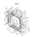
- Figure 1 is a perspective view of a first embodiment of the key removal apparatus of the present invention.
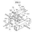
- Figure 2 is an exploded view of the main sections of the apparatus shown in Figure 1.
- Figure 3 is a front view of the key removal apparatus shown in Figure 1.
- Figure 4 is a side view of the key removal apparatus shown in Figure 3.
- Figure 5 is an illustration to explain the key rotation device of the first embodiment.
- Figure 6 is an illustration to explain the key moving device of the first embodiment.
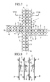
- Figure 7 is a partial plan view of the grid to explain the central section of the grid.
- Figure 8 is a partial cross sectional view at the line VIII-VIII in Figure 7.
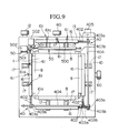
- Figure 9 is a front view of the key removal apparatus of a second embodiment of the present invention.
- Figure 10 is a side view of the key removal apparatus shown in Figure 9.
- Figure 11 is a front view showing a right side of the key removal apparatus shown in Figure 9.
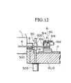
- Figure 12 is a cross sectional view of the main sections of the key removal apparatus shown in Figure 9.
- Prior to insertion of the fuel rods into the grid cells, a plurality of inner keys are used to deflect the springs from the dimples formed in the gird cells. The key removal apparatus is used to remove the inner keys from the opening sections of the grids after the fuel rods have been inserted into the girds. The key removal apparatus can be used singly or in a multiple set to hold the grids of the fuel assembly. The key removal apparatus is brought to the fully loaded assembly containing a plurality of grids and the key removal apparatus is fitted to the grids through the opening section of a U-shaped receptor of the key removal apparatus. Once the grids are properly seated in the receptor, the closure member is put in place to hold the grids firmly in place. The rest of the removal steps are carried out while firmly holding the grid or grids in the U-shaped receptor.
- In the following, various embodiments of the present invention will be explained with reference to Figures 1 to 12. Figures 1 to 6 show the first embodiment, and Figures 9 to 12 show a second embodiment of the key removal apparatus.
- Figures 7 and 8 show the arrangement of the
dimples 2 andsprings 3 formed ingrids cells 7 in certain limited regions of thegird 1. As shown in Figure 7, the arrangement is symmetrical with respect to an axis at right angles to the paper passing through the center O formed by the intersection of a line X-X and a line Y-Y. Thedimples 2 and thesprings 3 are disposed so that they are symmetrical in each of the four quadrants. In Figure 7, thereference numeral 4 and 5designate grid cells 7 for housing control rod guide pipe and instrumentation pipes, respectively. In Figure 8, thereference numeral 6 designates an inner key. - As shown in Figures 1 to 6, the key removal apparatus comprises: a main
post member 10 having aU-shaped receptor 10a which houses agrid 1; aclosure member 13 which closes the opening section of theU-shaped receptor 10a; a press-downmember 14 provided on themain posts 10 and theclosure members 13, for holding down thegrid 1 in thereceptor 1 Oa; afluidic cylinder 15 for operating the press-downmember 14 towards and away from thegrid 1; fourkey rotation devices 20 which rotates the plurality ofinner keys 6 inserted through the opening section of thegrid 1 about their key axis; two keymoving devices 30 which moves the plurality ofinner keys 6 inserted in thegrid 1 along the key axis. Theclosure member 13 is attached to themain post 10 through a support axis 11, shown in Figure 3, and closes or opens the opening section in the direction of the arrow shown in Figure 3 by ascending or descending along the support axis 11 as well as by rotating around the support axis 11. Thegrid 1 is held firmly in place by means of thefastener 12. - The
reference numeral 8 refers to an outer key which are used to deflect theoutermost springs 3 from thedimples 2 formed on the outer straps which form the grid cells 7 (referto Figure 2). It is mentioned here again that the key removal apparatus is used after thegrids 1 have been loaded with the plurality of fuel rods, and theinner keys 6 have been inserted into thegirds cells 7 through the opening section at right angles to the fuel rods. - The four
key rotation devices 20 are movably provided at the three edges of themain post 10 as well as for theclosure member 13, and thekey rotation devices 20 are disposed on the movingblocks 16 so as to move towards or away from thegrid 1 which is housed in thereceptor 10a. In other words, there are many (16 pieces) engagingmembers 200 rotatably provided on the movingblocks 16, and eachengaging member 200 is formed with a rectangular-shaped through hole 210 for fittingly engaging aninner key 6 therein. - In Figure 5, it is shown that each
arm member 202 extending from theengaging member 200 is engaged with a connectingplate 204 of alink member 203 through apin 205. The end of the connectingplate 204 is rotatably connected to arotation member 206 provided with arotation device 207. Each of therotation device 207, consisting of a set of eightengaging members 200, is rotated in opposite directions. This is because thedimples 2 and thesprings 3, as explained earlier with reference to Figures 7 and 8, are arranged in four quadrants, symmetrically with respect to the lines X-X and Y-Y intersecting at thepoint 0. - Figure 6 shows the key moving
device 30 viewed in the direction of key which is clamped between a pair ofclamping members 301. The movingblock 16 slides on a pair ofslide rails 17. - As shown in Figures 1 and 3, the moving
block 16 is connected to thedriving device 18, such as a fluidic cylinder or motor, to move the movingblock 16 along theslide rails 17 towards or away from thegrid 1. - The two key
moving devices 30 mentioned above are disposed as a paired set on one edge of themain post 10 and on the adjacent closure member 13 (in Figure 3, right edge and the top edge). As shown in Figures 2 and 6, the key movingdevice 30 comprises: sixteen pairs ofclamping members 301 disposed on each movingblock 16, each pair being connected to the movingblock 16 via asupport axis 300 so as to be openable or closable; a pair of connectingplates 304 of thelink member 303 rotatably connected to theclamping members 301 through connectingpins 302; arotation member 305 rotatably connected to theconnecting plates 304; a closing/opening motor 306 connected to therotation member 305 through atransmission device 307; and adriving device 18 which moves thedriving block 16 along theslide rails 17. - The key removal apparatus of the first embodiment as constructed above performs the following key removal operation. Before the apparatus is installed on the
grid 1, theclosure member 13 is rotated about the support axis 11 to swing theclosure member 13 away from the opening section of themain post 10. Each of the movingblock 16 is separated from theU-shaped receptor 10a by moving it along the slide rails 17 by operating the drivingdevice 18. In this condition, thegrids 1 loaded with the fuel rods and having theinner keys 6 andouter keys 8 inserted in thegrids 1 is placed in theU-shaped receptor 10a of themain post 10. Theclosure member 13 is rotated about the support axis 11, and after closing the opening section of themain post 10 by moving theclosure member 13 along the support axis 11, theclosure member 13 is fixed in place with afastener 12. - At this time, each moving
block 16 is moved closer to thegrid 1 housed in theU-shaped receptor 10a by moving them along the slide rails 17 by operating the drivingdevice 18. In this condition, each end part of theinner keys 6 which had been inserted into thegrids 1 are positioned between the pair of clampingmembers 301 of the key movingdevice 30. Then, both end portions of theinner keys 6 are inserted into the respective rectangular throughhole 201 of the engagingmembers 200 of the opposing pairs of thekey rotation device 20. - At this time, the
rotation device 207 which are provided as a pair on each movingblock 16 are operated, and each set of eightengaging members 200 is rotated respectively in opposite direction. As a result, each of theinner keys 6 which is engaged in the rectangular throughhole 201 of the engagingmember 200 is rotated through 90 degrees, through the same angle as the engagingmember 200. By so doing, the protrusion sections of theinner keys 6, which had been holding thespring 3 away from the fuel rod surface, are disengaged from thespring 3, thus allowing thespring 3 to extend by its own elasticity force toward thedimple 2 to touch the fuel rod, and thereby holding the fuel rod in place. This process may occur simultaneously in all thegrid cells 7 of a plurality ofgrids 1 when a multiple of grids are being processed. - In the next phase of the key removal operation, the closing/
opening motor 306 is operated, and the ends of theinner keys 6 are clamped with the pair of clampingmembers 301 by rotating the clampingmembers 301 about thesupport axis 300. In this condition, the drivingdevice 18 is operated to separate the movingblock 16 away from thegrids 1, then theinner keys 16 clamped by theclamping device 301 move along with theclamping device 301 for a distance equal to the stroke distance, governed by the fluidic cylinder, of the drivingdevice 18. - Next, the closing/
opening motor 306 is operated so as to open the pairs of clampingmembers 301 by rotating them about thesupport axis 300, thereby releasing the ends of theinner keys 6 from the clamping force of the clampingmembers 301. By operating the drivingdevice 18 and moving the movingblock 16 closer to thegrids 1 along the slide rails 17. - The clamping
members 301 are again closed on theinner keys 6, and theinner keys 6 with the clamping device are moved as described above. By repeating the above process, eachinner keys 6 is moved a distance at a time, and eventually removed completely from thegrids 1. - It is also possible to remove the
inner keys 6 by using a key removing apparatus presented in a second embodiment shown in Figures 9 to 12. - In this apparatus, the
key rotation device 20 and the key movingdevice 30 are replaced with the keyrotating device 40 and thekey mover device 50, and thefluidic cylinder 15 to drive the press-down member 14 are replaced with a press-down bolt 60. Wherever the structures in the second embodiment are the same as those in the first embodiment, they are given the same reference numbers, and their explanations are omitted. - The key
rotating devices 40 are provided on each of the four movingblocks 16. The keyrotating device 40 comprises: a plurality ofengagement members 400 each having a rectangular-shaped through hole; timingpulleys 401 disposed on the outer periphery of each of theengagement members 400; a pair ofendless belts 402 each of which is installed on a set of eight timing pulleys; a set ofunidirectional clutches endless belts 402. Furthermore, the four sets ofunidirectional clutches shafts 404 disposed at right angles to each other. Each of the two drivingshafts 404 is connected to a rotation motor 405 (only one is shown in Figure 9). - The set of
unidirectional clutches shafts 404 is made so that onebelt 402 is rotated in one direction, and theother belt 402 is rotated in the opposite direction for one rotational direction of the drivingshafts 404 which can rotate in either clockwise or counter clockwise directions. Also the driving shaft404 and the unidirectional clutch 403a, 403b are splined so that when the movingblock 16 moves along the slide rails 17, theunidirectional clutches shaft 404. - Further, an engaging
device 61 for engaging theinner keys 6 is provided respectively on the movingblock 16 disposed on theclosure member 13 and on the movingblock 16 disposed on the edge of themain post 10 adjacent to the closure member 13 (the left and top edges in Figure 9). As shown in Figures 10 and 12, this engagingdevice 61 comprises: a support rod 61 b which rotates about a support point 61a; a press-down jig 61c disposed on the tip of the support rod 61 b and presses down on theinner key 6; and an engaging cylinder 61d disposed on the base of the support rod 61 b for rotating the support rod 61 b. - The
key mover device 50 is provided to correspond with each of the engagingdevice 61, and comprises: a pair of revolvingrollers 500 which clamp theinner key 6; arotation motor 502 connected to the revolvingroller 500 through atransmission jig 501 for rotating the revolvingroller 500; and areciprocating cylinder 503 for rotatably supporting the revolvingroller 500 and for moving the revolvingroller 500 towards or away from theinner key 6. - The key removing apparatus of the second embodiment constructed as above performs the same function as the key removing apparatus presented in the first embodiment. The
grid 1 is fixed in theU-shaped receptor 1 Oa of themain post 10, and the driving device is activated to move the movingblock 16 along the slide rails 17 closer to thegrid 1. Both ends of theinner keys 6 inserted in thegrid 1 are inserted into the rectangular through holes formed on theengagement members 400 of the keyrotating device 40. - The operation of the second embodiment will be explained separately for the pair of driving
shafts 404 driven by the associated pair of rotation motors 405 (only one in shown in Figure 9). For example, in one group, there is onerotation motor 405, which transmits the rotation force through a unidirectional clutch 403a disposed on the end of the drivingshaft 404, to operate a set of eightengagement members 400. When the rotation motor405 is rotated in clockwise direction, a clutch 403a associated with anendless belt 402 and eight timingpulleys 401 and eightengagement members 400 are rotated in the clockwise direction. As a result, the eightinner keys 6 which are inserted into the rectangular through holes on one set of theengagement members 400 are also rotated as a set in the clockwise direction through 90 degrees. - The
other rotation motor 405 is operated next, and the other drivingshaft 404 is rotated in the counter clockwise (c/c) direction. The rotational force is transmitted to the other unidirectional clutch 403b to rotate theendless belt 402 and the timing pulleys 401 to rotate the remaining eightengagement members 400 in the c/c direction. As a result, the remaining eightinner keys 6 engaged in the rectangular through holes of theengagement members 400 are also rotated in the c/c direction through 90 degrees. - As described above, by rotating the axis of each of the two
rotation motors 405 through 90 degrees in clockwise and counter clockwise directions through 90 degrees, theinner keys 6 are disengaged from thesprings 3 in thegrid 1. By so doing, thespring 3 extend out by its own elasticity force towards thedimple 2, thereby firmly holding the fuel rod between thespring 2 and thedimple 3 in thegrid cells 7. - Next, the engaging cylinder 61d of the engaging
device 61 are operated to rotate the support rod 61 b about the support point 61a, the press-down jig 61c is made to press on each of theinner keys 6. The movingblock 16 having the engagingdevice 61 is moved away from thegrid 1. Theinner keys 6 attached to the press-down jigs 61c are also moved away from thegrid 1 along with the movement of the movingblock 16. The distance moved is governed by the stroke of the drivingdevice 18. - Next, the engaging cylinder 61d of the engaging
device 61 is operated to disengage the press-down jig 61c from theinner keys 6, then while clamping the end of each of theinner keys 6 with therotating rollers 500 by operating thereciprocating cylinder 503, therotation motor 502 is rotated to rotate the revolvingrollers 500 until theinner keys 6 are completely removed from thegrid 1. - Each of the above embodiments was based on a combination of the
key rotation device 20 with the key movingdevice 30, and a combination of the keyrotating device 40 and thekey mover device 50. However, it is clear that other key removal apparatus of similar performance may be provided by combining the keyrotating device 40 with the key movingdevice 30 or by combining thekey rotation device 20 with thekey mover device 50.
Claims (11)
Applications Claiming Priority (2)
| Application Number | Priority Date | Filing Date | Title |
|---|---|---|---|
| JP284774/92 | 1992-10-22 | ||
| JP04284774A JP3137769B2 (en) | 1992-10-22 | 1992-10-22 | Key removal device for support grid |
Publications (2)
| Publication Number | Publication Date |
|---|---|
| EP0594416A1 true EP0594416A1 (en) | 1994-04-27 |
| EP0594416B1 EP0594416B1 (en) | 1996-04-03 |
Family
ID=17682843
Family Applications (1)
| Application Number | Title | Priority Date | Filing Date |
|---|---|---|---|
| EP93308357A Expired - Lifetime EP0594416B1 (en) | 1992-10-22 | 1993-10-20 | Apparatus for removing keys from support grid |
Country Status (4)
| Country | Link |
|---|---|
| US (1) | US5396526A (en) |
| EP (1) | EP0594416B1 (en) |
| JP (1) | JP3137769B2 (en) |
| DE (1) | DE69302071T2 (en) |
Cited By (1)
| Publication number | Priority date | Publication date | Assignee | Title |
|---|---|---|---|---|
| CN115798757A (en) * | 2022-12-19 | 2023-03-14 | 中国原子能科学研究院 | Target cutting and loosening device |
Families Citing this family (2)
| Publication number | Priority date | Publication date | Assignee | Title |
|---|---|---|---|---|
| JP2009505077A (en) * | 2005-08-12 | 2009-02-05 | マリンクロッド・インコーポレイテッド | Radiation shielding assembly with container positioning mechanism |
| US8369475B2 (en) * | 2009-07-01 | 2013-02-05 | Westinghouse Electric Company Llc | Nuclear fuel assembly support grid |
Citations (4)
| Publication number | Priority date | Publication date | Assignee | Title |
|---|---|---|---|---|
| EP0105779A1 (en) * | 1982-09-16 | 1984-04-18 | SOCIETE COGEMA, FRAMATOME et URANIUM PECHINEY | Appliance and process for welding nuclear fuel assembly structural elements |
| EP0196609A1 (en) * | 1985-03-28 | 1986-10-08 | Westinghouse Electric Corporation | Arrangement for loading fuel rods into grids of a fuel assembly |
| JPH02221890A (en) * | 1989-02-21 | 1990-09-04 | Mitsubishi Nuclear Fuel Co Ltd | Support lattice for fuel assembly |
| US5068081A (en) * | 1989-01-06 | 1991-11-26 | Mitsubishi Nuclear Fuel Co. | Method of inserting fuel rods into a nuclear fuel assembly grid |
Family Cites Families (9)
| Publication number | Priority date | Publication date | Assignee | Title |
|---|---|---|---|---|
| US3795040A (en) * | 1971-10-28 | 1974-03-05 | Babcock & Wilcox Co | Method of inserting fuel rods into individual cells in a fuel element grid |
| US3892027A (en) * | 1971-10-28 | 1975-07-01 | Babcock & Wilcox Co | Industrial technique |
| US3894327A (en) * | 1973-10-23 | 1975-07-15 | Babcock & Wilcox Co | Industrial technique |
| US4624400A (en) * | 1983-10-21 | 1986-11-25 | Westinghouse Electric Corp. | Electromagnetic probe drive apparatus |
| US5259010A (en) * | 1991-09-30 | 1993-11-02 | B&W Nuclear Service Company | Replacement spacer pin with locking keys |
| JP3105042B2 (en) * | 1991-10-24 | 2000-10-30 | 三菱原子燃料株式会社 | Method of assembling fuel assembly and assembling apparatus used therefor |
| JPH05196787A (en) * | 1991-10-24 | 1993-08-06 | Mitsubishi Nuclear Fuel Co Ltd | Assembling device for fuel assembly |
| JP3073287B2 (en) * | 1991-11-08 | 2000-08-07 | 三菱原子燃料株式会社 | Key attachment / detachment device |
| JP3095502B2 (en) * | 1991-12-26 | 2000-10-03 | 三菱原子燃料株式会社 | Nuclear fuel assembly assembly device |
-
1992
- 1992-10-22 JP JP04284774A patent/JP3137769B2/en not_active Expired - Fee Related
-
1993
- 1993-10-20 EP EP93308357A patent/EP0594416B1/en not_active Expired - Lifetime
- 1993-10-20 DE DE69302071T patent/DE69302071T2/en not_active Expired - Fee Related
- 1993-10-21 US US08/139,035 patent/US5396526A/en not_active Expired - Lifetime
Patent Citations (4)
| Publication number | Priority date | Publication date | Assignee | Title |
|---|---|---|---|---|
| EP0105779A1 (en) * | 1982-09-16 | 1984-04-18 | SOCIETE COGEMA, FRAMATOME et URANIUM PECHINEY | Appliance and process for welding nuclear fuel assembly structural elements |
| EP0196609A1 (en) * | 1985-03-28 | 1986-10-08 | Westinghouse Electric Corporation | Arrangement for loading fuel rods into grids of a fuel assembly |
| US5068081A (en) * | 1989-01-06 | 1991-11-26 | Mitsubishi Nuclear Fuel Co. | Method of inserting fuel rods into a nuclear fuel assembly grid |
| JPH02221890A (en) * | 1989-02-21 | 1990-09-04 | Mitsubishi Nuclear Fuel Co Ltd | Support lattice for fuel assembly |
Non-Patent Citations (1)
| Title |
|---|
| PATENT ABSTRACTS OF JAPAN vol. 14, no. 525 (P - 1132) 19 November 1990 (1990-11-19) * |
Cited By (1)
| Publication number | Priority date | Publication date | Assignee | Title |
|---|---|---|---|---|
| CN115798757A (en) * | 2022-12-19 | 2023-03-14 | 中国原子能科学研究院 | Target cutting and loosening device |
Also Published As
| Publication number | Publication date |
|---|---|
| US5396526A (en) | 1995-03-07 |
| JPH06138287A (en) | 1994-05-20 |
| DE69302071T2 (en) | 1996-09-05 |
| EP0594416B1 (en) | 1996-04-03 |
| DE69302071D1 (en) | 1996-05-09 |
| JP3137769B2 (en) | 2001-02-26 |
Similar Documents
| Publication | Publication Date | Title |
|---|---|---|
| EP0594416B1 (en) | Apparatus for removing keys from support grid | |
| CH651166A5 (en) | DEVICE FOR SUPPORTING MICROPLATES AND A MICROPLATE TRANSPORT ASSEMBLY. | |
| DE2558963A1 (en) | DEVICE FOR FITTING SEMI-CONDUCTOR PLATES | |
| EP0769205A1 (en) | Device for treating wafer-shaped objects, especially silicon wafers | |
| EP0140025B1 (en) | Nuclear fuel rod bundle transfer apparatus | |
| DE19611713A1 (en) | Device for processing flat workpieces, such as. B. cards or book documents | |
| US4825032A (en) | Workpiece handling assembly | |
| JPS5929939A (en) | Controller for air current | |
| KR940003706B1 (en) | Device and method ofr gripping and detaching a top nozzle subassembly from a reconstitutable fuel assembly | |
| EP0594415B1 (en) | Apparatus for removing keys from a support grid a of nuclear fuel assembly | |
| CH669913A5 (en) | ||
| US5342160A (en) | Opener for irradiation capsule | |
| US5313507A (en) | Apparatus for attaching key member to nuclear fuel assembly grid and detaching same therefrom | |
| CN107790546B (en) | Punching device for pipe fittings | |
| EP3960669A1 (en) | Stack manipulating system and corresponding method | |
| JPH05196787A (en) | Assembling device for fuel assembly | |
| CN218707016U (en) | Angle steel feeding clamp | |
| SE502256C2 (en) | Device for controlling a tool | |
| KR102528395B1 (en) | Apparatus for maintaining distribution cable space | |
| CN212892523U (en) | Battery spacing adjustment divides material structure | |
| CN219292102U (en) | Agricultural product vision sorting actuating mechanism | |
| CN218658968U (en) | Quick door leaf turnover mechanism | |
| CN211395475U (en) | Gate capable of being rapidly disassembled | |
| CN219734819U (en) | Monitoring assembly | |
| CN219131442U (en) | Assembling machine for locking valve |
Legal Events
| Date | Code | Title | Description |
|---|---|---|---|
| PUAI | Public reference made under article 153(3) epc to a published international application that has entered the european phase |
Free format text: ORIGINAL CODE: 0009012 |
|
| AK | Designated contracting states |
Kind code of ref document: A1 Designated state(s): BE DE FR GB |
|
| RIN1 | Information on inventor provided before grant (corrected) |
Inventor name: YAMAZAKI, SHUJI, C/O TOHKAI SEISAKU, MIT.NUC.F.CO Inventor name: YOSHIDA, MASASHI, TOHKAI SEISAKU, MIT.NUC.F.CO. Inventor name: KOIWAI, TAICHI, C/O TOHKAI SEISAKU, MIT.NUC.F.CO. Inventor name: OHUCHI, KATSUNORI, TOHKAI SEISAKU, MIT.NUC.F.CO. Inventor name: OYAMA, JUNICHI, C/O TOHKAI SEISAKUSHO MITSUBISHI |
|
| RIN1 | Information on inventor provided before grant (corrected) |
Inventor name: YAMAZAKI, SHUJI, C/O TOHKAI SEISAKUSHO Inventor name: YOSHIDA, MASASHI, TOHKAI SEISAKUSHO Inventor name: KOIWAI, TAICHI, C/O TOHKAI SEISAKUSHO Inventor name: OHUCHI, KATSUNORI, C/O TOHKAI SEISAKUSHO Inventor name: OYAMA, JUNICHI C/O TOHKAI SEISAKUSHO |
|
| 17P | Request for examination filed |
Effective date: 19940628 |
|
| 17Q | First examination report despatched |
Effective date: 19950630 |
|
| GRAH | Despatch of communication of intention to grant a patent |
Free format text: ORIGINAL CODE: EPIDOS IGRA |
|
| GRAA | (expected) grant |
Free format text: ORIGINAL CODE: 0009210 |
|
| AK | Designated contracting states |
Kind code of ref document: B1 Designated state(s): BE DE FR GB |
|
| REF | Corresponds to: |
Ref document number: 69302071 Country of ref document: DE Date of ref document: 19960509 |
|
| ET | Fr: translation filed | ||
| PLBE | No opposition filed within time limit |
Free format text: ORIGINAL CODE: 0009261 |
|
| STAA | Information on the status of an ep patent application or granted ep patent |
Free format text: STATUS: NO OPPOSITION FILED WITHIN TIME LIMIT |
|
| 26N | No opposition filed | ||
| PGFP | Annual fee paid to national office [announced via postgrant information from national office to epo] |
Ref country code: DE Payment date: 19981023 Year of fee payment: 6 |
|
| PGFP | Annual fee paid to national office [announced via postgrant information from national office to epo] |
Ref country code: BE Payment date: 19981216 Year of fee payment: 6 |
|
| PG25 | Lapsed in a contracting state [announced via postgrant information from national office to epo] |
Ref country code: BE Free format text: LAPSE BECAUSE OF NON-PAYMENT OF DUE FEES Effective date: 19991031 |
|
| BERE | Be: lapsed |
Owner name: MITSUBISHI NUCLEAR FUEL CO. Effective date: 19991031 |
|
| PG25 | Lapsed in a contracting state [announced via postgrant information from national office to epo] |
Ref country code: DE Free format text: LAPSE BECAUSE OF NON-PAYMENT OF DUE FEES Effective date: 20000801 |
|
| REG | Reference to a national code |
Ref country code: GB Ref legal event code: IF02 |
|
| PGFP | Annual fee paid to national office [announced via postgrant information from national office to epo] |
Ref country code: FR Payment date: 20121018 Year of fee payment: 20 |
|
| PGFP | Annual fee paid to national office [announced via postgrant information from national office to epo] |
Ref country code: GB Payment date: 20121017 Year of fee payment: 20 |
|
| REG | Reference to a national code |
Ref country code: GB Ref legal event code: PE20 Expiry date: 20131019 |
|
| PG25 | Lapsed in a contracting state [announced via postgrant information from national office to epo] |
Ref country code: GB Free format text: LAPSE BECAUSE OF EXPIRATION OF PROTECTION Effective date: 20131019 |