EP0140025B1 - Nuclear fuel rod bundle transfer apparatus - Google Patents
Nuclear fuel rod bundle transfer apparatus Download PDFInfo
- Publication number
- EP0140025B1 EP0140025B1 EP84110367A EP84110367A EP0140025B1 EP 0140025 B1 EP0140025 B1 EP 0140025B1 EP 84110367 A EP84110367 A EP 84110367A EP 84110367 A EP84110367 A EP 84110367A EP 0140025 B1 EP0140025 B1 EP 0140025B1
- Authority
- EP
- European Patent Office
- Prior art keywords
- rollers
- bundle
- fuel rods
- drive
- container
- Prior art date
- Legal status (The legal status is an assumption and is not a legal conclusion. Google has not performed a legal analysis and makes no representation as to the accuracy of the status listed.)
- Expired
Links
Images


Classifications
-
- G—PHYSICS
- G21—NUCLEAR PHYSICS; NUCLEAR ENGINEERING
- G21C—NUCLEAR REACTORS
- G21C19/00—Arrangements for treating, for handling, or for facilitating the handling of, fuel or other materials which are used within the reactor, e.g. within its pressure vessel
- G21C19/34—Apparatus or processes for dismantling nuclear fuel, e.g. before reprocessing ; Apparatus or processes for dismantling strings of spent fuel elements
-
- Y—GENERAL TAGGING OF NEW TECHNOLOGICAL DEVELOPMENTS; GENERAL TAGGING OF CROSS-SECTIONAL TECHNOLOGIES SPANNING OVER SEVERAL SECTIONS OF THE IPC; TECHNICAL SUBJECTS COVERED BY FORMER USPC CROSS-REFERENCE ART COLLECTIONS [XRACs] AND DIGESTS
- Y02—TECHNOLOGIES OR APPLICATIONS FOR MITIGATION OR ADAPTATION AGAINST CLIMATE CHANGE
- Y02E—REDUCTION OF GREENHOUSE GAS [GHG] EMISSIONS, RELATED TO ENERGY GENERATION, TRANSMISSION OR DISTRIBUTION
- Y02E30/00—Energy generation of nuclear origin
- Y02E30/30—Nuclear fission reactors
Definitions
- This invention relates generally to storage of nuclear fuel rods and more particularly to the consolidation and storage of spent nuclear fuel rods.
- the fuel rod assemblies comprising the core of the nuclear reactor must be rearranged with the depleted or spent fuel assemblies being replaced with fresh ones.
- the spent fuel assemblies are removed from the reactor vessel and generally stored in a pool of water on the reactor site. Since a conventional fuel assembly comprises structures other than fuel rods such as grids and control rod guide tubes, a spent fuel rod assembly occupies more space in the storage pool than would be required for the individual fuel rods. Because the storage pool has a finite volume, it is desirable to arrange the fuel rods in a closely packed array and with a minimum of support structure to thereby maximize the amount of spent nuclear fuel that can be stored in a given volume of the storage pool. Increasing the fuel rod packing density during storage increases the available temporary storage capacity for the spent fuel rods until the fuel rods are transported off the reactor site for storage or reprocessing.
- the spent fuel rods have been irradiated during reactor operation, they are highly radioactive and can be handled only by remote manipulators and while the fuel rods are submerged in a coolant.
- the radioactive nature of the spent fuel rod assemblies increases the difficulty of not only transporting the spent fuel rod assembly but of also dismantling the fuel rod assembly and storing the spent fuel rods.
- the present invention provides a transferring apparatus for a nuclear fuel rod bundle from a first container to a second container located vertically underneath the first container.
- the invention in its broad form comprises apparatus for transferring a bundle of nuclear fuel rods along a path from a first container to a superjacent second container, the second container being aligned with and disposed beneath the first container, said rod transferring apparatus using rollers and being disposed at the bottom of the first container, characterized by (a) means to mount at least one set of rollers to space them apart so as to permit the distance between the axes of the rollers to be varied from a first distance, whereat space between the rollers is sufficient for receiving the bundle of fuel rods and converging them to a second distance less than said first distance, whereat said rollers engage opposing sides of the bundle of nuclear fuel rods; (b) a hatch disposed in use between a first position intercepting said path and retaining the bundle of fuel rods within the first container, and a second position permitting the bundle of nuclear fuel rods to be transferred from the first container to the second container; (c) remotely controlled drive means coupled with each of said rollers for rotatably driving said rollers to engagingly move said
- a nuclear fuel rod bundle drive apparatus drives the rods along a path from a first container to a second container.
- the second container is aligned with and disposed beneath the first container.
- the nuclear rod bundle transferring apparatus comprises two sets of rollers, each set mounted to permit the distance between the axes of the rollers to be varied from a first distance, wherein space between the rollers is sufficient for receiving the bundle of fuel rods, to a second distance, less than said first distance, wherein the rollers engage opposing sides of the bundle of nuclear fuel rods.
- a hatch is disposable between a first position intercepting the path and retaining the bundle of fuel rods within the first container, and a second position permitting the bundle of nuclear fuel rods to be transferred from the first container to the second container.
- a drive mechanism is coupled with each of the rollers for rotatably driving the rollers in opposite directions.
- a mechanism is provided for disposing the rollers the second distance apart to permit the rollers to engage and to be rotatably driven by the drive mechanism to move the bundle of nuclear fuel rods from the first container to the second container.
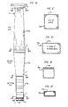
- Figure 1A is a perspective view of the spent fuel consolidation system
- Figure 1 B is a side view of the transition canister
- Figures 1C to 1F are respectively cross-sections of a bundle of nuclear fuel rods as the bundle is successively reconfigured at points a, b, c and d, respectively along the length of the transition canister;
- the spent fuel rod consolidation system for remotely dismantling a spent nuclear fuel rod assembly and removing its fuel rods, while the fuel rod assembly remains submerged in a coolant, and for consolidating the spent fuel rods into a compact array for more dense storage in the storage pool.
- the spent fuel rod consolidation system comprises a rotatable platform 20 that is capable of rotating about its vertical axis under the influence of a drive system (not shown) and that is capable of operating while completely submerged in the storage pool.
- Platform 20 comprises a vertical support 22, a fuel assembly station 24, a consolidation station 26 and a storage can station 28.
- Fuel assembly station 24, consolidation station 26, and storage can station 28 are attached to support plate 30 which is rotatably attached to vertical support 22.
- Support plate 30 is arranged such that when it is rotated about vertical support 22, fuel assembly station 24, consolidation station 26 and storage can station 28 may be selectively positioned with respect to gripper mechanism 32 which is slidably mounted on vertical support 22.
- a nozzle removal mechanism 34 is also arranged near platform 20 for removing a top nozzle (not shown) from fuel assembly 38.
- the fuel rod assembly 38 may take the form of that assembly manufactured by Babcock and Wilcox comprised of an array of 15 x 15 rods including 208 fuel rods, 16 guide thimble tubes and a centrally located instrumentation tube.
- the fuel assembly 38 may be one as described in US-A-3,791,466.
- fuel assembly station 24 provides a station for holding the spent fuel assembly 38 while its top nozzle and spent fuel rods 40 are removed therefrom.
- the fuel rods 40 are generally cylindrical metallic tubes containing nuclear fuel as is well understood in the art.
- Consolidation station 26 supports a transition canister 72, which provides a mechanism for rearranging fuel rods 40 into closely packed configurations.
- Storage can station 28 provides a station for locating a storage can 84 for accepting and holding fuel rods 40 after fuel rods 40 have been consolidated by the transition canister 72.
- the nozzle removal mechanism 34 comprises an internal cutter mechanism 44 that is slidably mounted on positioning mechanism 46.
- Positioning mechanism 46 serves to position internal cutter mechanism 44 over the fuel assembly 38 originally disposed at the fuel assembly station 24. Since the typical fuel assembly 38 comprises a top nozzle (not shown) which is attached to a plurality of control rod guide tubes 52, it is necessary to cut control rod guide tubes 52 so that the upper portion of control rod guide tubes 52 and the top nozzle may be removed to expose the top ends of the spent fuel rods 40. Positioning mechanism 46 then removes the internal cutter mechanism 44 from the top nozzle.
- the internal cutter mechanism 44 is moved away from the fuel assembly station 24 and the gripper mechanism 32 is moved downwardly along vertical member 22 and into contact with the exposed fuel rods 40 of fuel assembly 38.
- Gripper mechanism 32 then grips each fuel rod 40 as previously described. With gripper mechanism 32 gripping each fuel rod 40, gripper mechanism 32 is moved upwardly along vertical support 22. Since the fuel rod assembly 38 is locked to the fuel assembly station 24, the upward pulling of fuel rods 40 by gripper mechanism 32 removes the fuel rods 40 from the remainder of the fuel rod assembly 38. In this manner, the fuel rods 40 can be removed from the remainder of the fuel assembly 38.
- platform 20 may be rotated which will cause consolidation station 26 to be positioned under the gripper mechanism 32 and the fuel rods 40.
- the gripper mechanism 32 is lowered along vertical support 22 so that fuel rods 40 are inserted into the transition canister 72 originally disposed at the consolidation station 26.
- the transition canister 72 rearranges the fuel rods 40 as fuel rods 40 are lowered into transition canister 72 thereby closely packing fuel rods 40.
- the gripper mechanism 32 releases the fuel rods 40 so that the fuel rods 40 are completely contained in the transition canister 72.
- the gripper mechanism 32 by means of a conventional gripper (not shown), is caused to grip transition canister 72.
- the gripper mechanism 32 While holding the transition canister 72, the gripper mechanism 32 is again raised along the vertical support 22 until the transition canister 72 with the fuel rods 40 therein is raised clear of the consolidation station 26. With the transition canister 72 lifted clear of the consolidation station 26, the platform 20 is again rotated until the storage can station 28 is located under the transition canister 72, as shown in Figure 1A. When the transition canister 72 is over the storage can station 28, the gripper mechanism 32 is lowered thereby positioning the transition canister 72 on the storage can 84 disposed at the storage can station 28. With the transition canister 72 positioned on the storage can 84, the bottom end of the transition canister 72 is remotely opened and the fuel rods 40 disposed into the storage can 84 in a densely packed array or bundle.
- each storage can 84 may be arranged with a divider so that each storage can 84 can hold more than one set of the consolidated fuel rods 40.
- the storage can 84 is the permanent storage depository for one or more bundles of nuclear fuel rods 40.
- the closely packed bundle of fuel rods 40 needs to be carefully transferred from the transition canister 72 to the storage can 84.
- Accidental or rough handling of the fuel rods 40 may cause damage thereto and possible release of nuclear materials contained therein. The release of such nuclear materials could possibly contaminate the reactor site and the storage pool of water.
- the transition canister 72 includes a top can 72a, a center can 72b, and a bottom can 72c.
- a fuel rod bundle drive mechanism 80 in accordance with the teachings of this invention, is generally illustrated as being attached at the bottom of the transition canister 72 and, in particular, at the bottom of the bottom can 72c.
- the bundle 36 of nuclear fuel rods 40 is lowered into the transition canister 72.
- the cross-section of the bundle 36a at point "a" of the transition canister 12 is substantially square, as shown in Figure 1C.
- the transition canister 72 reconfigures the bundle 36 to those configurations, as shown in Figures 1D, 1E and 1F, corresponding respectively to the bundle configurations appearing at points b, c and d, as shown in Figure 1B.
- the bundle 36d is of a rectangular configuration having a relatively long, longitudinal dimension and a relatively short, side dimension.
- the nuclear fuel rods 40 are disposed in immediate contact with adjacent fuel rods 40.
- each fuel rod 40 fits into a concave space formed between abutting fuel rods 40.
- the fuel rods 40 disposed along the side dimension of the bundle 36d are spaced from each other.
- the bundle 36d is an optimum, densely packed array of the fuel rods 40.
- the bundle 36d of fuel rods 40 is directed by the fuel rod bundle drive mechanism 80 of this invention from the transition cansister 72 into a storage can 84, maintaining the fuel rods 40 in the same densely packed bundle 36d.
- the nuclear fuel rod drive mechanism 80 includes a pair of drive rollers 106, one of which is illustrated in Figure 1B, each drive roller 106 has a plurality of serrations for receiving and maintaining the relative positions of those fuel rods 40 as disposed along the length of the bundles 36d.
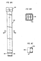
- FIG. 8A there is shown a side view of the storage can 84 for receiving the bundle 36d of nuclear fuel rods 40 from the fuel rod bundle drive mechanism 80.
- the storage can 84 is of a length corresponding to that of the nuclear fuel rods 40 and includes a bottom flow plate 89 against which the fuel rods 40 abut when inserted within the storage can 84.
- An energy absorber 88 is disposed against the bottom flow plate 89 to absorb the energy of the nuclear fuel rods 40 as they are disposed within the storage can 84, thus, minimizing possible damage to the nuclear fuel rods 40.
- the storage can 84 includes a lifting lug 85, whereby the storage can 84, after being filled with two bundles 36d of nuclear fuel rods 40, may be readily conveyed to its final storage location, e.g., a storage pool.
- the storage can 84 comprises two compartments 84a and 84b formed by partitioning wall 87 disposed therebetween.
- a first bundle 36d will be inserted by the fuel rod drive mechanism 80 into the compartment 84a and, after repositioning the drive mechanism 80 with respect to the storage can 84, a second bundle 36d of nuclear fuel rods 40 will be loaded into the compartment 84b.
- the storage can 84 is disposed at the storage can station 28 and is supported there by a temporary holding retainer 90, as shown in Figure 8D.
- the temporary holding retainer 90 provides the' storage can station 28 for holding the storage can 84, while the fuel rod bundle drive mechanism 80 transfers the nuclear fuel rods 40 from the transition canister 72 into the storage can 84. It is understood that gripper mechanism 32 is necessary to position the transition canister 72 with respect to the temporary holding retainer 90 and, therefore, the storage can 84 held therein.
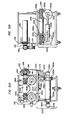
- the rod bundle drive mechanism 80 comprises an upper drive assembly 100, as will be explained in greater detail below with respect to Figures 5 and 6, and a lower drive assembly 200.
- the fuel rod bundle drive mechanism 80 is disposed beneath and is adapted to be secured to the transition canister 72.
- the upper drive assembly 100 of the mechanism 80 comprises a mounting plate 130 that abuts a bottom plate 81 of the transition canister 72 and is securely coupled thereto by a fastener in the form of a plurality of bolts 82, one of which is shown in Figure 3.
- the upper drive assembly 100 includes at least two threaded alignment pins 162 that are adapted to mate in openings of a mounting plate 230 of the lower drive assembly 200 and to be secured thereto by nuts.
- the upper drive assembly 100 includes the pair of drive rollers 106a and 106b that are rotatingly driven in opposite directions to drive the fuel rods 40 therebetween from the transition canister 72.
- the pair of rollers 106a and 106b abut and drivingly engage the long dimension of the bundle 36d of fuel rods 40.
- the lower drive assembly 200 includes a pair of rollers 208a and 208b (only roller 208a is shown) for abutting and drivingly engaging the short dimension of the bundle 36d of fuel rods 40.
- Each pair of rollers 106 and 206 is variably spaced from each other to permit each set of rollers to clamp the bundle of fuel rods 40, as will be explained below.
- a hatch 274 is mounted to be driven from an open position, as shown in Figure 2, to a closed position covering an opening 273 within a support plate 78 of a frame-like structure 74, thereby retaining the bundle of fuel rods 40 within the transition canister 72.
- the hatch 274 is driven between its open and closed positions by a pair of hydraulic drive cylinders 276a and 276b.
- the drive cylinders 276a and 276b are respectively mounted upon the support plate 78 by a pair of brackets 278a and 278b.
- the drive cylinders 276a and 276b respectively drive pistons 280a and 280b.
- the free end of each of the drive pistons 280a and 280b is coupled to an opposing end of a drive member 282.
- the drive member 282 is attached to drive the hatch 274 rectilinearly between its open and closed positions.
- the hatch 274 is received within guide grooves 286a and 286b, respectively, of a pair of guide rails 284a and 284b, each of which is secured to the support plate 78.
- the guide rails 284a and 284b permit the rectilinear motion of the hatch along the bottom surface of the support plate 78.
- the transition canister 72 is adapted to be lowered onto the temporary holding retainer 90 and, in particular, the storage can 84 by the frame-like structure 74 comprised of the support plate 78 and four upright members 76a, 76b, 76c (not shown) and 76d.
- a plurality of aligning pins 83a, 83b and 83c project downwardly from the support plate 78 to facilitate alignment of the frame-like structure 74 with a like array of openings 92 within the temporary holding retainer 90.
- the temporary holding retainer includes a flange 94 having a plurality of openings 92a to 92f therein.
- the three aligning pins 83a, 83b and 83c are inserted within a corresponding set of three openings 92, whereby the rod bundle drive mechanism 80 is aligned with one of the compartments of the storage can 84.
- the frame-like structure 74 is lifted from the temporary holding retainer 90, repositioned and again lowered onto the temporary holding retainer 90.
- the aligning pins 83a, 83b and 83c are disposed within other of the openings 92, whereby the rod bundle drive mechanism 80 is aligned to transport the nuclear fuel rods 40 of the compacted bundle 36d into the second compartment of the storage can 84.
- the storage can 84 is removed from the temporary holding retainer 90 and disposed within the final storage location, e.g., a storage pool located at the reactor site.
- the upper drive assembly 100 comprises the pair of rollers 106a and 106b mounted within a rectangularly-shaped frame 102 comprised of four side panels 104a, 104b, 104c and 104d.
- the drive roller 106a has a pair of end shafts 112a and 112b axially extending from either end thereof, whereas the drive roller 106b has a pair of end shafts 112c and 112d axially extending from either end thereof.
- the end shafts 112c and 112d are rotatingly received within a pair of corresponding bearings 114c and 114d.
- the bearings 114c and 114d are disposed respectively within the side panels 104b and 104d. As illustrated in Figure 5, the bearings 114c and 114d are fixedly disposed with respect to their side panels 104b and 104d to stationarily mount the roller 106b with respect to the bundle of fuel rods 40.
- the end shafts 112a and 112b are rotatively mounted with a pair of corresponding sliding axial bearings 114a and 114d, which are disposed respectively within elongated slots 110a and 110b of the side panels 104b and 104d, respectively, to permit rectilinear motion of the drive roller 106a with respect to the drive roller 106b.
- the spacing between the axes of the drive rollers 106a and 106b may be varied, whereby the bundle of fuel rods 40 may be engaged and released.
- a pair of drive cylinders 120a and 120b provide the mechanism for disposing the drive roller 106a towards the drive roller 106b, thereby bringing the drive rollers 106 into a driving engagement with the bundle of fuel rods 40.
- each of the drive cylinders 120a and 120b is mounted within a mounting lug 122a and 122b disposed on the side panel 104a.
- Jam nuts 124a and 124b are associated with corresponding drive cylinders 120a and 120b, whereby its position with respect to the sliding axial bearings 114a and 114b and, thus, the drive roller 106a, may be adjustably set.
- the drive cylinders 120a and 120b include drive members 126a and 126b, respectively, that abuts against a corresponding one of the sliding axial bearings 114a and 114b.
- the drive members 126a and 126b and, thus, the corresponding sliding axial bearings 114a and 114b are moved to the right, as shown in Figure 5.
- a canned pneumatic motor 132 is mounted adjacent the side panel 104c.
- the canned pneumatic motor 132 rotatably drives a miter gear 138, which matingly engages a miter gear 140.
- the miter gear 140 is, in turn, fixedly coupled to a common drive shaft 142.
- the drive shaft 142 is disposed through an opening 146 within a bearing block 144, which is mounted upon the slide panel 104d.
- the common drive shaft 142 rotatably drives a pair of worms 148a and 148b.
- the worms 148a and 148b respectively engage and drive worm gears 150a and 150b.
- the worm gears 150a and 150b are fixedly coupled to the end shafts 112b and 112d of the drive rollers 106a and 106b, respectively.
- the canned pneumatic motor 132 imparts a clockwise rotational drive via the worm gear 150a to the drive roller 106a, and a counterclockwise rotational drive via the worm gear 150b to the drive roller 106b.
- a thrust bearing 116a is disposed about the end shaft 112a of the drive roller 106a and a collar 118a is affixedly secured to the end of the end shaft 112a.
- a thrust bearing 116b is disposed between the sliding axial bearing 114b and the worm gear 150a.
- a thrust bearing 116c is disposed about the shaft 112c and a collar 118c is affixed to the end shaft 112c of the drive roller 106b.
- a thrust bearing 116d is disposed between the bearing 114d and the worm gear 150b of the drive roller 106b.
- each of the drive rollers 106a and 106b includes a plurality of serrations 108a and 108b for receiving therein the fuel rods 40.
- the radii of the serrations 108 are determined such that the fuel rods are aligned in contact with each other when disposed within the serrations 108 of the rollers 106.
- the drive shaft 142 is rotatably disposed within the bearing block 144.
- the miter gear 140 is affixedly attached to the lefthand end of the drive shaft 142, as shown in Figure 6.
- a spacer 150 is disposed to position the worm 148b.
- a thrust bearing 152 separates the worm 148 from the bearing block 144.
- a thrust bearing 154 and a spacer 156 are disposed about the drive shaft 142 and between the bearing block 144 and the worm 148a.
- a spacer 158 is disposed about the drive shaft 142, as retained thereon by a collar 160 affixedly attached to the end of the drive shaft 142.
- the lower drive assembly 200 will be more fully explained with respect to Figures 3 and 4.
- the lower drive assembly 200 is comprised of the upper mounting plate 230 and a lower mounting plate 270, between which is disposed a pair of side panels 204a and 204b.
- the side panels 204a and 204b receive the respective end shafts of the drive rollers 206a and 206b (not shown).
- Each of the drive rollers 206a and 206b is mounted in sliding bearings and receives a clamping force from a pair of contracting hydraulic cylinders 220a and 220b, as coupled to the end shafts 212 of each of the drive rollers 206a and 206b.
- opposing end shafts 212a and 212b of the drive roller 206a are mounted within sliding axial bearings 214a and 214b, respectively.
- end shaft 212b of the drive roller 206a extending to the left, as seen in Figures 3 and 9A, is coupled to a coupling bearing 260c, which is in turn coupled to one end of the drive cylinder 220a, shown in Figure 4.
- the other end of the drive cylinder 220a is coupled to a similar coupling bearing 260d (not shown) attached to the end shaft of the opposing drive roller 206b.
- a like drive cylinder 220b is coupled to the end shafts 212a and 212c of corresponding drive rollers 206a and 206b by a corresponding pair of coupling bearings 260a and 260b.
- the coupling bearings 260 and, thus, the drive rollers 206 are driven toward each other, whereby the bundle of fuel rods 40 is clamped therebetween.
- the drive rollers 206a and 206b do not have serrations therein, but are provided with knurled surface 208 to enhance the friction between the drive rollers 206 and the fuel rods 40.
- the knurled surfaces 208 permit readjustment of the position of the fuel rods 40 with respect to each other.
- the drive rollers 206a and 206b provide dimensional support to the bundle of fuel rods 40 and a driving force to those fuel rods 40 disposed at the knurled sides of the drive rollers 200, which would otherwise tend to lag with respect to those fuel rods 40 driven by the drive rollers 106a and 106b, if the drive rollers 206a and 206b were not provided.
- the drive rollers 208a and 208b are also driven by the canned pneumatic motor 132.
- the miter gear 138, driven by the canned pneumatic motor 132 includes a first sprocket 139 rotatively driving a drive chain 141.
- the drive chain 141 is coupled to an interconnecting drive mechanism comprised of a second sprocket 270 driven by the chain 141.
- the sprocket 270 is affixed to a drive shaft 272 which is, in turn, connected to a third sprocket (not shown in the drawings).
- the third sprocket is rotatably driven by the shaft 272.
- a second drive chain 274 serves to interconnect the rotational drive imparted to the third sprocket to a fourth sprocket 239, as shown in Figure 9B, to rotatively drive a common drive shaft 242.
- a pair of worms 248a and 248b are rotatably driven by the common drive shaft 242 and, in turn, rotatably drive in opposite directions worm gears 250a and 250b. It is understood that the worm gears 250a and 250b respectively drive the drive rollers 206a and 206b.
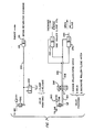
- FIG. 7 there is shown a hydraulic circuit for activating the drive cylinders 120.
- a source of pressurized air is coupled by an hydraulic pump 292 via a conduit 302 to the drive cylinders 120.
- a valve 290 is disposed between a first clamping position and a second release position. In the clamping position, pressure is established through the conduit 302 to the drive cylinders 120, whereby their drive members 126 are driven to the right, as shown in Figures 7 and 5, to thereby dispose likewise the drive roller 106a to the right.
- an air operated hydraulic pump 298 supplies hydraulic fluid via a conduit 304, a control valve 296 and a conduit 306 to the drive cylinders 220 and to the drive cylinders 276.
- a conduit 304 a control valve 296 and a conduit 306 to the drive cylinders 220 and to the drive cylinders 276.
- two similar drive cylinders, 276a and 276b are coupled to the hatch 274, as shown in Figure 2.
- two similar drive cylinders 220a and 220b are coupled to move the drive rollers 206 together, as illustrated in Figures 4 and 9B.
- a return or exhaust is provided by conduits 308 and 310.
- the control valve 296 is operative in a first position wherein pressure is introduced to a first side of the cylinders 220 and 276, whereby the hatch 274 is disposed to its open position, as shown in Figure 2, and the drive cylinders 220 serve to force together the rollers 206 coupled to opposite ends thereof.
- the control valve 296 has a second, hold position wherein pressure is maintained at an equilibrium within the cylinders 220 and 276.
- pressure is provided to the other sides of the cylinders 220 and 276, whereby the hatch 274 is disposed to its closed position covering the opening 273, as shown in Figure 2, and the drive cylinders 220 separate their drive rollers 206 to permit insertion of the bundle 36d of nuclear fuel rods 40 therebetween.
- the frame-like structure 74 carrying the rod bundle drive mechanism 80 of this invention is lowered onto the storage can 84.
- the rod bundle drive mechanism 80 is operated, as explained, to discharge the bundle of fuel rods 40 into the storage can 84.
- the aligning pins 83 are disposed into corresponding openings 92 of the temporary storage can 92, whereby the opening 273 within the support plate 78 is aligned with the storage can 84.
- hydraulic pressure is applied at the same time to the set of drive cylinders 220a and 220b and to the set of drive cylinders 276a and 276b to clamp both of the drive rollers 206a and 206b towards each other, while disposing the hatch 274 from its closed position covering the opening 273 to its next position, as shown in Figure 2.
- the hydraulic system of this invention is coupled in common to the drive cylinders 276a and 276b, and to the drive cylinders 220a and 220b, such that when the hatch 274 is closed, the drive rollers 206a and 206b are undamped, and when the hatch 274 is opened, the drive rollers 206a and 206b are clamped together.
- the canned pneumatic motor 132 is energized to drive both sets of the rollers 106 and 206.
- the drive rollers 106a and 106b are driven in opposite directions are as drive rollers 206a and 206b, whereby the bundle of fuel rods 40 is driven downwardly, as shown in Figures 2, 3 and 4, into the storage can 84.
- the invention as described above provides means for transferring the bundle of fuel rods for storage within the storage can.
Description
- This invention relates generally to storage of nuclear fuel rods and more particularly to the consolidation and storage of spent nuclear fuel rods.
- After a certain period of operation of a nuclear reactor, the fuel rod assemblies comprising the core of the nuclear reactor must be rearranged with the depleted or spent fuel assemblies being replaced with fresh ones. The spent fuel assemblies are removed from the reactor vessel and generally stored in a pool of water on the reactor site. Since a conventional fuel assembly comprises structures other than fuel rods such as grids and control rod guide tubes, a spent fuel rod assembly occupies more space in the storage pool than would be required for the individual fuel rods. Because the storage pool has a finite volume, it is desirable to arrange the fuel rods in a closely packed array and with a minimum of support structure to thereby maximize the amount of spent nuclear fuel that can be stored in a given volume of the storage pool. Increasing the fuel rod packing density during storage increases the available temporary storage capacity for the spent fuel rods until the fuel rods are transported off the reactor site for storage or reprocessing.
- However, since the spent fuel rods have been irradiated during reactor operation, they are highly radioactive and can be handled only by remote manipulators and while the fuel rods are submerged in a coolant. The radioactive nature of the spent fuel rod assemblies increases the difficulty of not only transporting the spent fuel rod assembly but of also dismantling the fuel rod assembly and storing the spent fuel rods.
- One method of handling spent fuel rods is described in European Patent Application EP-A-0066695 wherein in one particular arrangement, the spent fuel rods are consolidated while in a horizontal position, using rollers. In that method, one object is to remove the control rods from in between the spent fuel rods and consolidate the space occupied by the control rods so as to store the spent rods under water so as to occupy a much smaller cross-sectional area than when the control rods are present. In a horizontal position of the spent fuel rods, they are brought together by rollers.
- In some instances, there is need for the fuel rods to be transferred from a first container to a second vertical container. The prior art arrangement of EP-A-0066695 is not quite suitable for such purposes.
- The present invention provides a transferring apparatus for a nuclear fuel rod bundle from a first container to a second container located vertically underneath the first container.
- The invention in its broad form comprises apparatus for transferring a bundle of nuclear fuel rods along a path from a first container to a superjacent second container, the second container being aligned with and disposed beneath the first container, said rod transferring apparatus using rollers and being disposed at the bottom of the first container, characterized by (a) means to mount at least one set of rollers to space them apart so as to permit the distance between the axes of the rollers to be varied from a first distance, whereat space between the rollers is sufficient for receiving the bundle of fuel rods and converging them to a second distance less than said first distance, whereat said rollers engage opposing sides of the bundle of nuclear fuel rods; (b) a hatch disposed in use between a first position intercepting said path and retaining the bundle of fuel rods within the first container, and a second position permitting the bundle of nuclear fuel rods to be transferred from the first container to the second container; (c) remotely controlled drive means coupled with each of said rollers for rotatably driving said rollers to engagingly move said bundle of fuel rods; (d) actuatable means for disposing said hatch from its said first position to its said second position; and (e) remotely controlled actuatable means for disposing said rollers of said set at said second distance apart to permit said rollers to engage and to be rotatably driven by said drive means to move the bundle of nuclear fuel rods from the first container to the second container.
- In a preferred embodiment described herein, a nuclear fuel rod bundle drive apparatus drives the rods along a path from a first container to a second container. The second container is aligned with and disposed beneath the first container. The nuclear rod bundle transferring apparatus comprises two sets of rollers, each set mounted to permit the distance between the axes of the rollers to be varied from a first distance, wherein space between the rollers is sufficient for receiving the bundle of fuel rods, to a second distance, less than said first distance, wherein the rollers engage opposing sides of the bundle of nuclear fuel rods. A hatch is disposable between a first position intercepting the path and retaining the bundle of fuel rods within the first container, and a second position permitting the bundle of nuclear fuel rods to be transferred from the first container to the second container. A drive mechanism is coupled with each of the rollers for rotatably driving the rollers in opposite directions. A mechanism is provided for disposing the rollers the second distance apart to permit the rollers to engage and to be rotatably driven by the drive mechanism to move the bundle of nuclear fuel rods from the first container to the second container.
- While the specification concludes with claims particularly pointing out and distinctly claiming the subject matter of this invention, it is believed that this invention will be better understood from the following description taken in conjunction with the accompanying drawings, wherein:
- Figure 1A is a perspective view of the spent fuel consolidation system, Figure 1 B is a side view of the transition canister, and Figures 1C to 1F are respectively cross-sections of a bundle of nuclear fuel rods as the bundle is successively reconfigured at points a, b, c and d, respectively along the length of the transition canister;
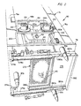
- Figure 2 is a perspective view of the fuel rod bundle drive mechanism particularly illustrating a bottom portion thereof and the discharge of spent fuel rods from a transition canister;
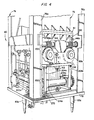
- Figures 3 and 4 are respectively a side view and a perspective view of the fuel rod bundle drive mechanism as shown in Figures 2 and 1 B;
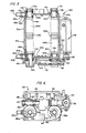
- Figures 5 and 6 are respectively a partially sectioned, top plan view and a side view of the upper drive assembly of the fuel rod bundle drive mechanism of a preferred embodiment of this invention;
- Figure 7 is a circuit diagram of the hydraulic system for driving the hydraulic cylinders incorporated within the fuel rod bundle drive mechanism;
- Figure 8A is a side view of a storage can for receiving the bundle of nuclear fuel rods from the transition canister, as shown in Figures 1A and 1B, Figure 8B is a plan view of the storage canister of Figure 8A, Figure 8C is a sectioned view of the storage can as taken through
lines 8C-8C of Figure 8A, and Figure 8D is a perspective view of the storage can and the bundle of fuel rods contained therein as disposed within and supported by a temporary holding retainer; and - Figures 9A and 98 are respectively elevation views of the front and the side of the fuel rod bundle drive mechanism.
- There is generally described a spent fuel consolidation system for remotely dismantling a spent nuclear fuel rod assembly and removing its fuel rods, while the fuel rod assembly remains submerged in a coolant, and for consolidating the spent fuel rods into a compact array for more dense storage in the storage pool. Referring to Figure 1A, the spent fuel rod consolidation system, as described in the above-identified application, comprises a
rotatable platform 20 that is capable of rotating about its vertical axis under the influence of a drive system (not shown) and that is capable of operating while completely submerged in the storage pool.Platform 20 comprises avertical support 22, afuel assembly station 24, aconsolidation station 26 and a storage canstation 28.Fuel assembly station 24,consolidation station 26, and storage canstation 28 are attached to supportplate 30 which is rotatably attached tovertical support 22.Support plate 30 is arranged such that when it is rotated aboutvertical support 22,fuel assembly station 24,consolidation station 26 and storage canstation 28 may be selectively positioned with respect togripper mechanism 32 which is slidably mounted onvertical support 22. Anozzle removal mechanism 34 is also arranged nearplatform 20 for removing a top nozzle (not shown) fromfuel assembly 38. In an illustrative embodiment of this invention, thefuel rod assembly 38 may take the form of that assembly manufactured by Babcock and Wilcox comprised of an array of 15 x 15 rods including 208 fuel rods, 16 guide thimble tubes and a centrally located instrumentation tube. Alternatively, thefuel assembly 38 may be one as described in US-A-3,791,466. - In general,
fuel assembly station 24 provides a station for holding thespent fuel assembly 38 while its top nozzle and spentfuel rods 40 are removed therefrom. Thefuel rods 40 are generally cylindrical metallic tubes containing nuclear fuel as is well understood in the art.Consolidation station 26 supports atransition canister 72, which provides a mechanism for rearrangingfuel rods 40 into closely packed configurations. Storage canstation 28 provides a station for locating a storage can 84 for accepting and holdingfuel rods 40 afterfuel rods 40 have been consolidated by thetransition canister 72. - The
nozzle removal mechanism 34 comprises aninternal cutter mechanism 44 that is slidably mounted onpositioning mechanism 46.Positioning mechanism 46 serves to positioninternal cutter mechanism 44 over thefuel assembly 38 originally disposed at thefuel assembly station 24. Since thetypical fuel assembly 38 comprises a top nozzle (not shown) which is attached to a plurality of controlrod guide tubes 52, it is necessary to cut controlrod guide tubes 52 so that the upper portion of controlrod guide tubes 52 and the top nozzle may be removed to expose the top ends of thespent fuel rods 40.Positioning mechanism 46 then removes theinternal cutter mechanism 44 from the top nozzle. - Next, the
internal cutter mechanism 44 is moved away from thefuel assembly station 24 and thegripper mechanism 32 is moved downwardly alongvertical member 22 and into contact with the exposedfuel rods 40 offuel assembly 38.Gripper mechanism 32 then grips eachfuel rod 40 as previously described. Withgripper mechanism 32 gripping eachfuel rod 40,gripper mechanism 32 is moved upwardly alongvertical support 22. Since thefuel rod assembly 38 is locked to thefuel assembly station 24, the upward pulling offuel rods 40 bygripper mechanism 32 removes thefuel rods 40 from the remainder of thefuel rod assembly 38. In this manner, thefuel rods 40 can be removed from the remainder of thefuel assembly 38. - With the
gripper mechanism 32 in its uppermost position,platform 20 may be rotated which will causeconsolidation station 26 to be positioned under thegripper mechanism 32 and thefuel rods 40. Next, thegripper mechanism 32 is lowered alongvertical support 22 so thatfuel rods 40 are inserted into thetransition canister 72 originally disposed at theconsolidation station 26. Thetransition canister 72 rearranges thefuel rods 40 asfuel rods 40 are lowered intotransition canister 72 thereby closely packingfuel rods 40. When thegripper mechanism 32 has reached its lowermost position, thegripper mechanism 32 releases thefuel rods 40 so that thefuel rods 40 are completely contained in thetransition canister 72. Next, thegripper mechanism 32 by means of a conventional gripper (not shown), is caused togrip transition canister 72. While holding thetransition canister 72, thegripper mechanism 32 is again raised along thevertical support 22 until thetransition canister 72 with thefuel rods 40 therein is raised clear of theconsolidation station 26. With thetransition canister 72 lifted clear of theconsolidation station 26, theplatform 20 is again rotated until the storage canstation 28 is located under thetransition canister 72, as shown in Figure 1A. When thetransition canister 72 is over the storage can station 28, thegripper mechanism 32 is lowered thereby positioning thetransition canister 72 on the storage can 84 disposed at the storage can station 28. With thetransition canister 72 positioned on the storage can 84, the bottom end of thetransition canister 72 is remotely opened and thefuel rods 40 disposed into the storage can 84 in a densely packed array or bundle. As shown in Figure 8C, each storage can 84 may be arranged with a divider so that each storage can 84 can hold more than one set of the consolidatedfuel rods 40. Once thefuel rods 40 have been deposited in the storage can 84,transition canister 72 may be returned to theconsolidation station 26 by lifting thetransition canister 72 and rotating theplatform 20 in a reverse direction. - The storage can 84 is the permanent storage depository for one or more bundles of
nuclear fuel rods 40. The closely packed bundle offuel rods 40 needs to be carefully transferred from thetransition canister 72 to the storage can 84. Accidental or rough handling of thefuel rods 40 may cause damage thereto and possible release of nuclear materials contained therein. The release of such nuclear materials could possibly contaminate the reactor site and the storage pool of water. - Referring now to the drawings and, in particular, to Figure 1B, there is shown a side view of the
transition canister 72, as more generally shown in Figure 1A. Thetransition canister 72 includes a top can 72a, a center can 72b, and abottom can 72c. A fuel rodbundle drive mechanism 80, in accordance with the teachings of this invention, is generally illustrated as being attached at the bottom of thetransition canister 72 and, in particular, at the bottom of thebottom can 72c. The bundle 36 ofnuclear fuel rods 40 is lowered into thetransition canister 72. The cross-section of thebundle 36a at point "a" of the transition canister 12 is substantially square, as shown in Figure 1C. Thetransition canister 72 reconfigures the bundle 36 to those configurations, as shown in Figures 1D, 1E and 1F, corresponding respectively to the bundle configurations appearing at points b, c and d, as shown in Figure 1B. In Figure 1F, thebundle 36d is of a rectangular configuration having a relatively long, longitudinal dimension and a relatively short, side dimension. Along the length dimension, as shown in Figure 1F, thenuclear fuel rods 40 are disposed in immediate contact withadjacent fuel rods 40. In an adjacent row offuel rods 40, eachfuel rod 40 fits into a concave space formed between abuttingfuel rods 40. As a result, thefuel rods 40 disposed along the side dimension of thebundle 36d, are spaced from each other. Thebundle 36d is an optimum, densely packed array of thefuel rods 40. As will be explained below, thebundle 36d offuel rods 40 is directed by the fuel rodbundle drive mechanism 80 of this invention from thetransition cansister 72 into astorage can 84, maintaining thefuel rods 40 in the same densely packedbundle 36d. To this end, the nuclear fuelrod drive mechanism 80 includes a pair ofdrive rollers 106, one of which is illustrated in Figure 1B, eachdrive roller 106 has a plurality of serrations for receiving and maintaining the relative positions of thosefuel rods 40 as disposed along the length of thebundles 36d. - Referring now to Figure 8A, there is shown a side view of the storage can 84 for receiving the
bundle 36d ofnuclear fuel rods 40 from the fuel rodbundle drive mechanism 80. The storage can 84 is of a length corresponding to that of thenuclear fuel rods 40 and includes abottom flow plate 89 against which thefuel rods 40 abut when inserted within thestorage can 84. Anenergy absorber 88 is disposed against thebottom flow plate 89 to absorb the energy of thenuclear fuel rods 40 as they are disposed within the storage can 84, thus, minimizing possible damage to thenuclear fuel rods 40. As shown in Figure 88, the storage can 84 includes a liftinglug 85, whereby the storage can 84, after being filled with twobundles 36d ofnuclear fuel rods 40, may be readily conveyed to its final storage location, e.g., a storage pool. As illustrated in Figure 8C, the storage can 84 comprises twocompartments 84a and 84b formed by partitioningwall 87 disposed therebetween. As will be described below, afirst bundle 36d will be inserted by the fuelrod drive mechanism 80 into the compartment 84a and, after repositioning thedrive mechanism 80 with respect to the storage can 84, asecond bundle 36d ofnuclear fuel rods 40 will be loaded into thecompartment 84b. - The storage can 84 is disposed at the storage can station 28 and is supported there by a
temporary holding retainer 90, as shown in Figure 8D. Thetemporary holding retainer 90 provides the' storage can station 28 for holding the storage can 84, while the fuel rodbundle drive mechanism 80 transfers thenuclear fuel rods 40 from thetransition canister 72 into thestorage can 84. It is understood thatgripper mechanism 32 is necessary to position thetransition canister 72 with respect to thetemporary holding retainer 90 and, therefore, the storage can 84 held therein. - Referring now to Figures 2, 3 and 4, the details of the fuel rod
bundle drive mechanism 80 are shown. The rodbundle drive mechanism 80 comprises anupper drive assembly 100, as will be explained in greater detail below with respect to Figures 5 and 6, and alower drive assembly 200. The fuel rodbundle drive mechanism 80 is disposed beneath and is adapted to be secured to thetransition canister 72. In particular, theupper drive assembly 100 of themechanism 80 comprises a mountingplate 130 that abuts abottom plate 81 of thetransition canister 72 and is securely coupled thereto by a fastener in the form of a plurality ofbolts 82, one of which is shown in Figure 3. As particularly shown in Figures 2, 4 and 6, theupper drive assembly 100 includes at least two threaded alignment pins 162 that are adapted to mate in openings of a mountingplate 230 of thelower drive assembly 200 and to be secured thereto by nuts. - As illustrated in Figures 5 and 6, the
upper drive assembly 100 includes the pair ofdrive rollers 106a and 106b that are rotatingly driven in opposite directions to drive thefuel rods 40 therebetween from thetransition canister 72. As seen in Figure 5, the pair ofrollers 106a and 106b abut and drivingly engage the long dimension of thebundle 36d offuel rods 40. As particularly illustrated in Figures 3 and 4, thelower drive assembly 200 includes a pair of rollers 208a and 208b (only roller 208a is shown) for abutting and drivingly engaging the short dimension of thebundle 36d offuel rods 40. Each pair ofrollers 106 and 206 is variably spaced from each other to permit each set of rollers to clamp the bundle offuel rods 40, as will be explained below. - As shown particularly in Figure 2,a
hatch 274 is mounted to be driven from an open position, as shown in Figure 2, to a closed position covering anopening 273 within asupport plate 78 of a frame-like structure 74, thereby retaining the bundle offuel rods 40 within thetransition canister 72. Thehatch 274 is driven between its open and closed positions by a pair ofhydraulic drive cylinders 276a and 276b. Thedrive cylinders 276a and 276b are respectively mounted upon thesupport plate 78 by a pair ofbrackets 278a and 278b. Thedrive cylinders 276a and 276b respectively drivepistons drive pistons drive member 282. As seen in Figure 2, thedrive member 282 is attached to drive thehatch 274 rectilinearly between its open and closed positions. Thehatch 274 is received withinguide grooves 286a and 286b, respectively, of a pair ofguide rails support plate 78. As a result, theguide rails support plate 78. - As particularly illustrated in Figures 3 and 4, the
transition canister 72 is adapted to be lowered onto thetemporary holding retainer 90 and, in particular, the storage can 84 by the frame-like structure 74 comprised of thesupport plate 78 and fourupright members 76a, 76b, 76c (not shown) and 76d. As particularly shown in Figure 2, a plurality of aligningpins support plate 78 to facilitate alignment of the frame-like structure 74 with a like array of openings 92 within thetemporary holding retainer 90. As shown in Figure 8D, the temporary holding retainer includes aflange 94 having a plurality of openings 92a to 92f therein. As the frame-like structure 74 is lowered onto thetemporary holding retainer 90, the three aligningpins bundle drive mechanism 80 is aligned with one of the compartments of thestorage can 84. After that compartment is filled withfuel rods 40, the frame-like structure 74 is lifted from thetemporary holding retainer 90, repositioned and again lowered onto thetemporary holding retainer 90. In the second position, the aligningpins bundle drive mechanism 80 is aligned to transport thenuclear fuel rods 40 of the compactedbundle 36d into the second compartment of thestorage can 84. After the storage can 84 has been filled with nuclear fuel rods, the storage can 84 is removed from thetemporary holding retainer 90 and disposed within the final storage location, e.g., a storage pool located at the reactor site. - Referring now to Figures 5 and 6, a more detailed explanation of the
upper drive assembly 100 will be provided. Theupper drive assembly 100 comprises the pair ofrollers 106a and 106b mounted within a rectangularly-shapedframe 102 comprised of fourside panels end shafts drive roller 106b has a pair ofend shafts end shafts corresponding bearings bearings side panels bearings side panels roller 106b with respect to the bundle offuel rods 40. By contrast, theend shafts axial bearings 114a and 114d, which are disposed respectively withinelongated slots 110a and 110b of theside panels drive roller 106b. In other words, the spacing between the axes of thedrive rollers 106a and 106b may be varied, whereby the bundle offuel rods 40 may be engaged and released. In particular, a pair ofdrive cylinders drive roller 106b, thereby bringing thedrive rollers 106 into a driving engagement with the bundle offuel rods 40. As particularly illustrated in Figure 5, each of thedrive cylinders lug 122a and 122b disposed on theside panel 104a. Jam nuts 124a and 124b are associated withcorresponding drive cylinders axial bearings 114a and 114b and, thus, the drive roller 106a, may be adjustably set. Thedrive cylinders drive members 126a and 126b, respectively, that abuts against a corresponding one of the slidingaxial bearings 114a and 114b. Thus, when the hydraulic pressure is increased within thedrive cylinders drive members 126a and 126b and, thus, the corresponding slidingaxial bearings 114a and 114b, are moved to the right, as shown in Figure 5. - Referring to both of Figures 5 and 6, an explanation of the drive mechanism for the
drive rollers 106a and 106b will be provided. A cannedpneumatic motor 132 is mounted adjacent theside panel 104c. The cannedpneumatic motor 132 rotatably drives amiter gear 138, which matingly engages amiter gear 140. Themiter gear 140 is, in turn, fixedly coupled to acommon drive shaft 142. Thedrive shaft 142 is disposed through anopening 146 within abearing block 144, which is mounted upon theslide panel 104d. Thecommon drive shaft 142 rotatably drives a pair ofworms 148a and 148b. As particularly illustrated in Figure 6, theworms 148a and 148b respectively engage and driveworm gears worm gears end shafts drive rollers 106a and 106b, respectively. In this manner, the cannedpneumatic motor 132 imparts a clockwise rotational drive via theworm gear 150a to the drive roller 106a, and a counterclockwise rotational drive via theworm gear 150b to thedrive roller 106b. - As shown in Figure 5, a thrust bearing 116a is disposed about the
end shaft 112a of the drive roller 106a and a collar 118a is affixedly secured to the end of theend shaft 112a. Athrust bearing 116b is disposed between the slidingaxial bearing 114b and theworm gear 150a. Similarly, a thrust bearing 116c is disposed about theshaft 112c and a collar 118c is affixed to theend shaft 112c of thedrive roller 106b. A thrust bearing 116d is disposed between the bearing 114d and theworm gear 150b of thedrive roller 106b. Further, each of thedrive rollers 106a and 106b includes a plurality ofserrations 108a and 108b for receiving therein thefuel rods 40. The radii of theserrations 108 are determined such that the fuel rods are aligned in contact with each other when disposed within theserrations 108 of therollers 106. - As shown in Figure 6, the
drive shaft 142, is rotatably disposed within thebearing block 144. Themiter gear 140 is affixedly attached to the lefthand end of thedrive shaft 142, as shown in Figure 6. Thereafter, aspacer 150 is disposed to position theworm 148b. Athrust bearing 152 separates the worm 148 from thebearing block 144. Athrust bearing 154 and aspacer 156 are disposed about thedrive shaft 142 and between thebearing block 144 and the worm 148a. Finally, aspacer 158 is disposed about thedrive shaft 142, as retained thereon by acollar 160 affixedly attached to the end of thedrive shaft 142. - The
lower drive assembly 200 will be more fully explained with respect to Figures 3 and 4. Thelower drive assembly 200 is comprised of the upper mountingplate 230 and alower mounting plate 270, between which is disposed a pair ofside panels side panels hydraulic cylinders 220a and 220b, as coupled to the end shafts 212 of each of the drive rollers 206a and 206b. In particular, opposingend shafts axial bearings end shaft 212b of the drive roller 206a extending to the left, as seen in Figures 3 and 9A, is coupled to acoupling bearing 260c, which is in turn coupled to one end of the drive cylinder 220a, shown in Figure 4. The other end of the drive cylinder 220a is coupled to a similar coupling bearing 260d (not shown) attached to the end shaft of the opposing drive roller 206b. As shown in Figure 9B, alike drive cylinder 220b is coupled to theend shafts coupling bearings 260a and 260b. When hydraulic pressure is applied to thedrive cylinders 220a and 220b, the coupling bearings 260 and, thus, the drive rollers 206 are driven toward each other, whereby the bundle offuel rods 40 is clamped therebetween. - Unlike the
drive rollers 106a and 106b, the drive rollers 206a and 206b do not have serrations therein, but are provided withknurled surface 208 to enhance the friction between the drive rollers 206 and thefuel rods 40. The knurled surfaces 208 permit readjustment of the position of thefuel rods 40 with respect to each other. The drive rollers 206a and 206b provide dimensional support to the bundle offuel rods 40 and a driving force to thosefuel rods 40 disposed at the knurled sides of thedrive rollers 200, which would otherwise tend to lag with respect to thosefuel rods 40 driven by thedrive rollers 106a and 106b, if the drive rollers 206a and 206b were not provided. - Referring now to Figures 9A and 9B, the drive rollers 208a and 208b are also driven by the canned
pneumatic motor 132. Themiter gear 138, driven by the cannedpneumatic motor 132, includes afirst sprocket 139 rotatively driving adrive chain 141. In turn, thedrive chain 141 is coupled to an interconnecting drive mechanism comprised of asecond sprocket 270 driven by thechain 141. In turn, thesprocket 270 is affixed to adrive shaft 272 which is, in turn, connected to a third sprocket (not shown in the drawings). The third sprocket is rotatably driven by theshaft 272. As shown in Figure 9A, asecond drive chain 274 serves to interconnect the rotational drive imparted to the third sprocket to afourth sprocket 239, as shown in Figure 9B, to rotatively drive acommon drive shaft 242. A pair ofworms 248a and 248b are rotatably driven by thecommon drive shaft 242 and, in turn, rotatably drive in oppositedirections worm gears worm gears - Referring now to Figure 7, there is shown a hydraulic circuit for activating the
drive cylinders 120. Though only onedrive cylinder 120 is shown in Figure 7, it is understood that two such drive cylinders, 120a and 120b, are disposed within the system, corresponding to the configuration shown in Figure 5. In particular, a source of pressurized air is coupled by anhydraulic pump 292 via aconduit 302 to thedrive cylinders 120. Avalve 290 is disposed between a first clamping position and a second release position. In the clamping position, pressure is established through theconduit 302 to thedrive cylinders 120, whereby theirdrive members 126 are driven to the right, as shown in Figures 7 and 5, to thereby dispose likewise the drive roller 106a to the right. Further, an air operatedhydraulic pump 298 supplies hydraulic fluid via a conduit 304, acontrol valve 296 and aconduit 306 to thedrive cylinders 220 and to thedrive cylinders 276. Though only asingle drive cylinder 276 is illustrated in Figure 7, it is understood that two similar drive cylinders, 276a and 276b, are coupled to thehatch 274, as shown in Figure 2. Likewise, though only asingle drive cylinder 220 is illustrated in Figure 7, it is understood that twosimilar drive cylinders 220a and 220b are coupled to move the drive rollers 206 together, as illustrated in Figures 4 and 9B. A return or exhaust is provided byconduits control valve 296 is operative in a first position wherein pressure is introduced to a first side of thecylinders hatch 274 is disposed to its open position, as shown in Figure 2, and thedrive cylinders 220 serve to force together the rollers 206 coupled to opposite ends thereof. Thecontrol valve 296 has a second, hold position wherein pressure is maintained at an equilibrium within thecylinders cylinders hatch 274 is disposed to its closed position covering theopening 273, as shown in Figure 2, and thedrive cylinders 220 separate their drive rollers 206 to permit insertion of thebundle 36d ofnuclear fuel rods 40 therebetween. - In summary, the frame-
like structure 74 carrying the rodbundle drive mechanism 80 of this invention, is lowered onto thestorage can 84. Once mounted, the rodbundle drive mechanism 80 is operated, as explained, to discharge the bundle offuel rods 40 into thestorage can 84. The aligning pins 83 are disposed into corresponding openings 92 of the temporary storage can 92, whereby theopening 273 within thesupport plate 78 is aligned with thestorage can 84. When the frame-like structure 74 has been so aligned with the storage can 84, hydraulic pressure is applied to each of thedrive cylinders drive members 126a and 126b are disposed in unison to the right, as shown in Figure 5, whereby the drive roller 106a is likewise disposed to the right and the space between thedrive rollers 106a and 106b is reduced. As a result, thedrive rollers 106a and 106b are forced together to grip and to hold thefuel rod bundle 36d along the long dimension of thebundle 36d offuel rods 40. Next, hydraulic pressure is applied at the same time to the set ofdrive cylinders 220a and 220b and to the set ofdrive cylinders 276a and 276b to clamp both of the drive rollers 206a and 206b towards each other, while disposing thehatch 274 from its closed position covering theopening 273 to its next position, as shown in Figure 2. The hydraulic system of this invention is coupled in common to thedrive cylinders 276a and 276b, and to thedrive cylinders 220a and 220b, such that when thehatch 274 is closed, the drive rollers 206a and 206b are undamped, and when thehatch 274 is opened, the drive rollers 206a and 206b are clamped together. After both sets of thedrive rollers pneumatic motor 132 is energized to drive both sets of therollers 106 and 206. As explained above, thedrive rollers 106a and 106b are driven in opposite directions are as drive rollers 206a and 206b, whereby the bundle offuel rods 40 is driven downwardly, as shown in Figures 2, 3 and 4, into thestorage can 84. - The invention as described above, provides means for transferring the bundle of fuel rods for storage within the storage can.
Claims (10)
Applications Claiming Priority (2)
| Application Number | Priority Date | Filing Date | Title |
|---|---|---|---|
| US06/535,082 US4547117A (en) | 1983-09-23 | 1983-09-23 | Nuclear fuel rod bundle drive apparatus |
| US535082 | 1983-09-23 |
Publications (2)
| Publication Number | Publication Date |
|---|---|
| EP0140025A1 EP0140025A1 (en) | 1985-05-08 |
| EP0140025B1 true EP0140025B1 (en) | 1988-06-01 |
Family
ID=24132760
Family Applications (1)
| Application Number | Title | Priority Date | Filing Date |
|---|---|---|---|
| EP84110367A Expired EP0140025B1 (en) | 1983-09-23 | 1984-08-31 | Nuclear fuel rod bundle transfer apparatus |
Country Status (7)
| Country | Link |
|---|---|
| US (1) | US4547117A (en) |
| EP (1) | EP0140025B1 (en) |
| JP (1) | JPS6091292A (en) |
| KR (1) | KR910006875B1 (en) |
| CA (1) | CA1218771A (en) |
| DE (1) | DE3471802D1 (en) |
| ES (1) | ES8605120A1 (en) |
Families Citing this family (17)
| Publication number | Priority date | Publication date | Assignee | Title |
|---|---|---|---|---|
| US4704247A (en) * | 1981-08-10 | 1987-11-03 | U.S. Tool & Die Co., Inc. | Method and apparatus for compacting spent nuclear reactor fuel rods |
| US4714583A (en) * | 1981-08-10 | 1987-12-22 | U.S. Tool & Die, Inc. | Method and apparatus for compacting spent nuclear reactor fuel rods |
| FR2553226B1 (en) * | 1983-10-11 | 1987-01-02 | Fragema Framatome & Cogema | METHOD AND INSTALLATION FOR RECONSTRUCTING A NUCLEAR FUEL ASSEMBLY |
| EP0186161A3 (en) * | 1984-12-24 | 1987-12-02 | Combustion Engineering, Inc. | Canister for consolidation of nuclear fuel rods |
| DE3506584A1 (en) * | 1985-02-25 | 1986-08-28 | Kraftwerk Union AG, 4330 Mülheim | DEVICE FOR INSERTING NUCLEAR FUEL OR TUBES CONTAINING NEUTRON ABSORBENT IN A SPECIFIED SEALED PACK IN A CONTAINER |
| US4648989A (en) * | 1985-02-27 | 1987-03-10 | Wastechem Corporation | Underwater compressing and cutting apparatus |
| US4747995A (en) * | 1985-06-10 | 1988-05-31 | Widder Corporation | Velocity limiter shear for BWR control rods |
| US4659536A (en) * | 1985-06-14 | 1987-04-21 | Proto-Power Corporation | System and method for consolidating spent fuel rods |
| DE3530410A1 (en) * | 1985-08-26 | 1987-03-05 | Steag Kernenergie Gmbh | Method for compressing spent fuel elements and an arrangement for carrying out the method |
| FR2586854B1 (en) * | 1985-08-29 | 1987-12-04 | Framatome Sa | METHOD AND DEVICE FOR COMPACTING A BEAM OF FUEL PENCILS |
| US4762664A (en) * | 1985-12-30 | 1988-08-09 | U.S. Tool & Die, Inc. | Method and apparatus for compacting spent nuclear reactor fuel rods |
| FR2596565B1 (en) * | 1986-04-01 | 1988-07-01 | Cogema | PROCESS FOR FITTING A BEAM OF PENCILS OF A NUCLEAR FUEL ASSEMBLY AND INSTALLATION FOR CARRYING OUT SAID METHOD |
| US5000906A (en) * | 1987-06-18 | 1991-03-19 | Westinghouse Electric Corp. | System and method for removing and consolidating the fuel rods of a nuclear fuel assembly |
| US4952072A (en) * | 1987-06-18 | 1990-08-28 | Westinghouse Electric Corp. | System and method for removing and consolidation fuel rods of a nuclear fuel assembly |
| ES2043723T3 (en) * | 1987-06-18 | 1994-01-01 | Westinghouse Electric Corp | SYSTEM TO REMOVE AND ASSEMBLE FUEL BARS FROM A NUCLEAR FUEL ASSEMBLY. |
| US4968477A (en) * | 1989-02-02 | 1990-11-06 | Westinghouse Electric Corp. | Method and apparatus for removing the fuel rods of a nuclear fuel assembly |
| EP2057972A1 (en) | 2007-11-07 | 2009-05-13 | N.V. Organon | Intrauterine deposit |
Family Cites Families (5)
| Publication number | Priority date | Publication date | Assignee | Title |
|---|---|---|---|---|
| US3807018A (en) * | 1970-12-15 | 1974-04-30 | Allied Chem | Apparatus for shearing spent nuclear fuel bundles |
| US4441242A (en) * | 1981-05-29 | 1984-04-10 | Westinghouse Electric Corp. | Spent fuel consolidation system |
| DE3268629D1 (en) * | 1981-05-29 | 1986-03-06 | Westinghouse Electric Corp | Spent fuel consolidation apparatus |
| US4446098A (en) * | 1981-05-29 | 1984-05-01 | Westinghouse Electric Corp. | Spent fuel consolidation system |
| FR2528218A1 (en) * | 1982-06-07 | 1983-12-09 | Transnucleaire | METHOD, INSTALLATION AND DEVICE FOR THE COMPACTION OF OBLONGED AND FLEXIBLE OBJECTS, IN PARTICULAR NUCLEAR REACTOR COMBUSTIBLE PENCILS |
-
1983
- 1983-09-23 US US06/535,082 patent/US4547117A/en not_active Expired - Lifetime
-
1984
- 1984-08-31 EP EP84110367A patent/EP0140025B1/en not_active Expired
- 1984-08-31 DE DE8484110367T patent/DE3471802D1/en not_active Expired
- 1984-09-19 CA CA000463646A patent/CA1218771A/en not_active Expired
- 1984-09-21 ES ES536161A patent/ES8605120A1/en not_active Expired
- 1984-09-21 JP JP59199335A patent/JPS6091292A/en active Pending
- 1984-09-22 KR KR1019840005827A patent/KR910006875B1/en active IP Right Grant
Also Published As
| Publication number | Publication date |
|---|---|
| EP0140025A1 (en) | 1985-05-08 |
| CA1218771A (en) | 1987-03-03 |
| ES536161A0 (en) | 1986-03-01 |
| JPS6091292A (en) | 1985-05-22 |
| KR850002357A (en) | 1985-05-10 |
| ES8605120A1 (en) | 1986-03-01 |
| KR910006875B1 (en) | 1991-09-09 |
| US4547117A (en) | 1985-10-15 |
| DE3471802D1 (en) | 1988-07-07 |
Similar Documents
| Publication | Publication Date | Title |
|---|---|---|
| EP0140025B1 (en) | Nuclear fuel rod bundle transfer apparatus | |
| US5291532A (en) | Fuel transfer system | |
| US8056217B2 (en) | Twist-lock handling system | |
| EP0782495B1 (en) | Robot installation | |
| US5304110A (en) | Magazine for tools and/or workpieces | |
| CN1178897A (en) | Assembling device for heat exchanging tube of heat exchanger and assembling method | |
| JPH0581715B2 (en) | ||
| EP0309470B1 (en) | Spent fuel rod horizontal consolidation system and method | |
| EP0181768B1 (en) | Remotely controlled apparatus for removing clips from irradiated nuclear fuel assemblies | |
| US4731219A (en) | Method and apparatus for compacting a bundle of fuel elements | |
| EP0295451B1 (en) | A system for removing and consolidating the fuel rods of a nuclear fuel assembly | |
| AU670690B2 (en) | Loading apparatus and methods | |
| US3827579A (en) | Irradiated fuel processing system | |
| US4952072A (en) | System and method for removing and consolidation fuel rods of a nuclear fuel assembly | |
| US3621742A (en) | Irradiated fuel processing system | |
| US4960559A (en) | Capture row storage tray for holding collated rows of nuclear fuel pellets | |
| CN217654143U (en) | Automatic operation platform | |
| US5000906A (en) | System and method for removing and consolidating the fuel rods of a nuclear fuel assembly | |
| CN117141923B (en) | Polypropylene cable protection tube stacking device | |
| JP2954577B1 (en) | Automatic fuel rod collection device | |
| JPH11508050A (en) | Equipment for handling nuclear fuel rods | |
| AU2005279680B2 (en) | Twist-lock handling system | |
| EP0506275B1 (en) | Fuel rod consolidation structure | |
| KR20240028973A (en) | System and method for automatic calandria tube installation | |
| CN116944930A (en) | Tool magazine for vertical tool storage and retrieval |
Legal Events
| Date | Code | Title | Description |
|---|---|---|---|
| PUAI | Public reference made under article 153(3) epc to a published international application that has entered the european phase |
Free format text: ORIGINAL CODE: 0009012 |
|
| AK | Designated contracting states |
Designated state(s): BE DE FR GB IT SE |
|
| 17P | Request for examination filed |
Effective date: 19851018 |
|
| 17Q | First examination report despatched |
Effective date: 19860822 |
|
| ITF | It: translation for a ep patent filed |
Owner name: ING. ZINI MARANESI & C. S.R.L. |
|
| GRAA | (expected) grant |
Free format text: ORIGINAL CODE: 0009210 |
|
| AK | Designated contracting states |
Kind code of ref document: B1 Designated state(s): BE DE FR GB IT SE |
|
| REF | Corresponds to: |
Ref document number: 3471802 Country of ref document: DE Date of ref document: 19880707 |
|
| ET | Fr: translation filed | ||
| PLBE | No opposition filed within time limit |
Free format text: ORIGINAL CODE: 0009261 |
|
| STAA | Information on the status of an ep patent application or granted ep patent |
Free format text: STATUS: NO OPPOSITION FILED WITHIN TIME LIMIT |
|
| 26N | No opposition filed | ||
| ITTA | It: last paid annual fee | ||
| PGFP | Annual fee paid to national office [announced via postgrant information from national office to epo] |
Ref country code: SE Payment date: 19910617 Year of fee payment: 8 |
|
| PGFP | Annual fee paid to national office [announced via postgrant information from national office to epo] |
Ref country code: GB Payment date: 19910624 Year of fee payment: 8 |
|
| PGFP | Annual fee paid to national office [announced via postgrant information from national office to epo] |
Ref country code: DE Payment date: 19910930 Year of fee payment: 8 |
|
| PG25 | Lapsed in a contracting state [announced via postgrant information from national office to epo] |
Ref country code: GB Effective date: 19920831 |
|
| PG25 | Lapsed in a contracting state [announced via postgrant information from national office to epo] |
Ref country code: SE Effective date: 19920901 |
|
| GBPC | Gb: european patent ceased through non-payment of renewal fee |
Effective date: 19920831 |
|
| PG25 | Lapsed in a contracting state [announced via postgrant information from national office to epo] |
Ref country code: DE Effective date: 19930501 |
|
| PGFP | Annual fee paid to national office [announced via postgrant information from national office to epo] |
Ref country code: BE Payment date: 19930621 Year of fee payment: 10 |
|
| PGFP | Annual fee paid to national office [announced via postgrant information from national office to epo] |
Ref country code: FR Payment date: 19930630 Year of fee payment: 10 |
|
| PG25 | Lapsed in a contracting state [announced via postgrant information from national office to epo] |
Ref country code: BE Effective date: 19940831 |
|
| EUG | Se: european patent has lapsed |
Ref document number: 84110367.4 Effective date: 19930406 |
|
| BERE | Be: lapsed |
Owner name: WESTINGHOUSE ELECTRIC CORP. Effective date: 19940831 |
|
| PG25 | Lapsed in a contracting state [announced via postgrant information from national office to epo] |
Ref country code: FR Effective date: 19950428 |
|
| REG | Reference to a national code |
Ref country code: FR Ref legal event code: ST |