EP0309470B1 - Spent fuel rod horizontal consolidation system and method - Google Patents
Spent fuel rod horizontal consolidation system and method Download PDFInfo
- Publication number
- EP0309470B1 EP0309470B1 EP87903929A EP87903929A EP0309470B1 EP 0309470 B1 EP0309470 B1 EP 0309470B1 EP 87903929 A EP87903929 A EP 87903929A EP 87903929 A EP87903929 A EP 87903929A EP 0309470 B1 EP0309470 B1 EP 0309470B1
- Authority
- EP
- European Patent Office
- Prior art keywords
- rods
- fuel
- assembly
- station
- downender
- Prior art date
- Legal status (The legal status is an assumption and is not a legal conclusion. Google has not performed a legal analysis and makes no representation as to the accuracy of the status listed.)
- Expired - Lifetime
Links
Images

Classifications
-
- G—PHYSICS
- G21—NUCLEAR PHYSICS; NUCLEAR ENGINEERING
- G21C—NUCLEAR REACTORS
- G21C19/00—Arrangements for treating, for handling, or for facilitating the handling of, fuel or other materials which are used within the reactor, e.g. within its pressure vessel
- G21C19/34—Apparatus or processes for dismantling nuclear fuel, e.g. before reprocessing ; Apparatus or processes for dismantling strings of spent fuel elements
-
- Y—GENERAL TAGGING OF NEW TECHNOLOGICAL DEVELOPMENTS; GENERAL TAGGING OF CROSS-SECTIONAL TECHNOLOGIES SPANNING OVER SEVERAL SECTIONS OF THE IPC; TECHNICAL SUBJECTS COVERED BY FORMER USPC CROSS-REFERENCE ART COLLECTIONS [XRACs] AND DIGESTS
- Y02—TECHNOLOGIES OR APPLICATIONS FOR MITIGATION OR ADAPTATION AGAINST CLIMATE CHANGE
- Y02E—REDUCTION OF GREENHOUSE GAS [GHG] EMISSIONS, RELATED TO ENERGY GENERATION, TRANSMISSION OR DISTRIBUTION
- Y02E30/00—Energy generation of nuclear origin
- Y02E30/30—Nuclear fission reactors
-
- Y—GENERAL TAGGING OF NEW TECHNOLOGICAL DEVELOPMENTS; GENERAL TAGGING OF CROSS-SECTIONAL TECHNOLOGIES SPANNING OVER SEVERAL SECTIONS OF THE IPC; TECHNICAL SUBJECTS COVERED BY FORMER USPC CROSS-REFERENCE ART COLLECTIONS [XRACs] AND DIGESTS
- Y10—TECHNICAL SUBJECTS COVERED BY FORMER USPC
- Y10T—TECHNICAL SUBJECTS COVERED BY FORMER US CLASSIFICATION
- Y10T29/00—Metal working
- Y10T29/53—Means to assemble or disassemble
- Y10T29/531—Nuclear device
Definitions
- Spent fuel storage has traditionally been part of the responsibility of the operator of commercial nuclear plants. Many utilities anticipated that by this time there would be commercially accessible fuel reprocessing plants available and accordingly designed and constructed relatively small spent fuel pools. In some instances the storage pools are nearly full and further plant operations may have to be halted unless additional spent fuel can be disposed of. This storage problem has been recognized along with the short term solution of fuel consolidation by which fuel assemblies are disassembled and their components are compacted and canistered such that the volume occupied by the spent fuel elements is substantially reduced.
- U.S. Patent 4,446,098 is an example of a system in which the consolidation is shown as being carried out with the fuel assemblies and rods disposed in a vertical orientation, although horizontal consolidation is said to be equally effective.
- Belgian Patent 682,592 discloses an arrangement of handling nuclear fuel rods from assemblies wherein the fuel rods are pulled from the assembly in a horizontal position and randomly dropped into a container which is then lifted to a vertical position for cutting and consolidation of the rods.
- a horizontal system according to our invention need be no more than approximately 30 feet (9 m) in length. Some pools have apace available to accommodate this length.
- a horizontal system according to our invention may also be supported off the operating floor, or from empty storage racks requiring no floor space in reactor spent fuel pools. Further the system can be designed to eliminate any electrical power supplies required for operation and the system can be operated and actuated by long-handle tooling in reactor pools, or by impact wrenches and other tools in dry-hot cells.
- the present invention resides in an arrangement as defined in claim 1 and method as defined in claim 6.
- the system carries out the same basic process with a second assembly so that the storage canister, which has approximately the same transverse cross-sectional area as a single fuel assembly, receives the fuel rods from two fuel assemblies.
- Figure 1 The major parts of the system for carrying out the invention are illustrated in Figure 1 including a first downender station generally designated 10 and a second, rod extracting and reordering station generally designated 12.
- the downender station 10 includes a support 14 which carries a pivotal platform 16 which can be driven by gear drive 18 between its horizontal position shown in Figure 1 to a vertical position as shown in Figure 2.
- a fuel assembly generally designated 20 is shown in Figure 1 on the upper side of the platform 16 where it is securely held in place by clamps 22 which clamp over the requisite number of grids 24 of the fuel assembly to insure retention of the fuel assembly during manipulaiions and rod extraction.
- a rod storage canister 26 is secured to the under side of the platform by means of clamps 28.
- the platform 16 also carries a pivotal horizontal comb structure 30 and a vertical comb structure 32.
- the downender 10 is shown with the platform 18 disposed in a vertical orientation.
- a spent fuel assembly 20 from which the individual fuel rods are to be removed is shown apart from the downender with the arrow 34 indicating that the assembly is to be moved to the one face of the platform 18 so that the upper end of the assembly including the nozzle 36 will be in a position such that the guide tube cutter 38 can be easily positioned to register with the guide tubes to perform the cutting function.
- the general construction of one type of fuel assembly which may be disassembled in carrying out the invention is shown in U.S. Patent 3,791,466.
- the second station 12 is supported by structural frame means 46 so that the horizontal movable parts are properly aligned with the downender in its horizontal position.
- a pair of horizontal guide rails 48 support a carriage 50 adapted to be moved to an extended left position (Figure 1) or a retracted right position by a pair of screw drives 52 adapted to be rotated by a ball screw drive gear box 54 located at that end of the second station opposite the downender.
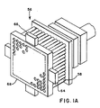
- the carriage 50 carries a multiple fuel rod gripper device 56 which has as many discrete gripper elements 58 (Figure 1A) as there are fuel rods to be gripped for the particular fuel assembly 20 which is to be disassembled.
- the currently preferred multiple rod gripper is of the split collet type which is a known type of gripper for rods of this type. Details about such grippers are found in U.S. Patent 4,551,299.
- the multiple rod gripper 56 is moved into position at the end of the second station 12 where the exposed ends of the fuel rods 44 are located. After all of the rods have been gripped by the gripper 56, the gripper is then moved, through operation of the ball screw drives 52 towards its retracted position at the right end of the second station. As the fuel rods are pulled progressively from the fuel assembly 20, successive horizontal and vertical combs 60 and 62 are successively actuated to interleave with the fuel rods to maintain the original square pitch array of the fuel rods.
- the individual fuel rods will have been moved to an upper horizontal position 69 in the second station and are supported in columns and rows as in their original square pitch array by the combs 60 and 62 and the gripper at the right end.
- a reconfiguring die or structure 70 Underlying this upper horizontal position of the rods is a reconfiguring die or structure 70 which has the basic transverse shape of an upwardly open rectangular box or trough. With the rods in the upper horizontal position the horizontal combs 60 are released by operating release linkage 71 and the multiple rod gripper in its retracted position is released, and the fuel rods will cascade down in vertical columns into the reconfiguring die 70.
- the reconfiguring structure 70 is supported by several jack screw drives 72 which permits the elevation of the reconfiguring structure to be changed.
- the carriage 50 also supports a rod pusher die 74 which will also be in a right end retracted position when the multiple rod gripper is in that location.
- the pusher die is mounted to the carriage through means, such as spring means, which will maintain the pusher die at the lower level of the reconfiguring structure. With the load of fuel rods 44 from the first fuel assembly to be disassembled in the reconfiguring structure because of the removal of the combs which maintained the original square pitch array, these rods are ready to be placed in the lower portion of the storage canister 26. If desired, additional means for finalizing the reordering of the fuel rods in the reconfiguring structure may be provided, such as a vibration system or some other arrangement.
- the carriage and pusher die 74 is driven from right to left to push the fuel rods into the lower part of the storage canister 26 as in Figure 6. It will be appreciated that as the pusher die moves the rods into the canister, the multiple rod gripper 56 is again moved to its extended position ready to accept the rods from the next fuel assembly.
- the downender platform 16 carrying the skeleton of the fuel assembly 20 is then moved again to a vertical position as in Figure 5 and the skeleton is then off loaded from the platform as indicated by the arrow 76 and a second intact spent fuel assembly is on loaded to the platform as indicated by the arrow 78.
- the upper nozzle and grid of the second fuel assembly is then removed as has been described hereinbefore and the downender platform 16 is returned to a horizontal position as in Figure 1.
- the removal of the rods is the same as described hereinbefore and the second set of rods are dropped into the reconfiguring structure 70, and pushed into the upper section of the storage canister 26.
- the storage canister is sized to have a transverse cross-sectional area approximately the same as that of an intact fuel assembly, and is capable of accepting the fuel rods of two fuel assemblies.
- different types of fuel assemblies may have different constructions which require clamping and nozzle removal means somewhat different than that described in connection with the example of a PWR type fuel assembly.
- a 7x7 BWR assembly all of the grids are clamped to the platform since there is no other structure than the fuel rods which will maintain the grids in their relative positions during removal of the rods.
- the BWR assemblies may have nuts securing the top end fitting of the assembly so that such nuts are removed to permit removal of the top end fitting.
- the gripper may be provided with spring release means which permit the release of an individual fuel rod when the pulling force exceeds a predetermined limit, such as 150 pounds (67 kg). In such cases the removal of the fuel rod from the remainder of the fuel assembly skeleton takes place in a way not a part of this invention.
- the system is a self-contained, remotely accessed system for use in either wet or dry environments for the disassembly and volume reduction of either spent BWR or PWR fuel assemblies.
- the overall length of the system is decreased by the length of the canister.
- This decrease in system length potentially provides the capability of "at reactor site” consolidation and pools.
- This system may also be supported from the side of the pool requiring no floor space to consolidate fuel in reactor pools.
- the system is designed to eliminate if necessary any electric power supplies required for operation. It can be operated and actuated by long-handled tooling in reactor pools, or impact wrenches in dry-hot cells.
Abstract
Description
- Spent fuel storage has traditionally been part of the responsibility of the operator of commercial nuclear plants. Many utilities anticipated that by this time there would be commercially accessible fuel reprocessing plants available and accordingly designed and constructed relatively small spent fuel pools. In some instances the storage pools are nearly full and further plant operations may have to be halted unless additional spent fuel can be disposed of. This storage problem has been recognized along with the short term solution of fuel consolidation by which fuel assemblies are disassembled and their components are compacted and canistered such that the volume occupied by the spent fuel elements is substantially reduced.
- So far as we know, most fuel rod consolidation systems have been designed with the fuel assembly axis vertically disposed to conform to the spent fuel pool physical space parameters.
- U.S. Patent 4,446,098 is an example of a system in which the consolidation is shown as being carried out with the fuel assemblies and rods disposed in a vertical orientation, although horizontal consolidation is said to be equally effective.
- Belgian Patent 682,592 discloses an arrangement of handling nuclear fuel rods from assemblies wherein the fuel rods are pulled from the assembly in a horizontal position and randomly dropped into a container which is then lifted to a vertical position for cutting and consolidation of the rods.
- It is our belief that there are advantages to providing a basically horizontal system for rod removal and consolidation. A horizontal system according to our invention need be no more than approximately 30 feet (9 m) in length. Some pools have apace available to accommodate this length. A horizontal system according to our invention may also be supported off the operating floor, or from empty storage racks requiring no floor space in reactor spent fuel pools. Further the system can be designed to eliminate any electrical power supplies required for operation and the system can be operated and actuated by long-handle tooling in reactor pools, or by impact wrenches and other tools in dry-hot cells.
- Accordingly, it is the aim of our invention to provide a fuel rod consolidation arrangement and method for handling spent fuel rods from a single fuel assembly at one time, which provides for efficient remote handling in a horizontal position.
- With this object in view, the present invention resides in an arrangement as defined in claim 1 and method as defined in claim 6. The system carries out the same basic process with a second assembly so that the storage canister, which has approximately the same transverse cross-sectional area as a single fuel assembly, receives the fuel rods from two fuel assemblies.
-
- Figure 1 is an isometric view, somewhat schematic in some details, of most of the basic equipment for carrying out the invention;
- Figure 1A is an isometric view, enlarged relative to Fig. 1, of a multiple, collet gripper assembly which may be used, for example, in the invention;
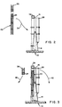
- Figure 2 is a mostly schematic view of the downender in a vertical position adapted to receive a fuel assembly;
- Figure 3 is a view similar to Figure 2 but with the fuel assembly in position and with the upper nozzle and first grid removed;
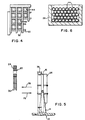
- Figure 4 is a fragmentary view illustrating the way a vertical comb and horizontal comb arrangement maintain the original square pitch array of the fuel rods;
- Figure 5 is a view of the downender again in a vertical position for off loading the skeleton of the fuel assembly from which fuel rods have been removed prior to reloading another fuel assembly on the downender; and
- Figure 6 is a fragmentary, transverse cross-sectional view through the storage canister to illustrate the compacted triangular pitched array of the fuel rods therein.
- The major parts of the system for carrying out the invention are illustrated in Figure 1 including a first downender station generally designated 10 and a second, rod extracting and reordering station generally designated 12.
- The
downender station 10 includes asupport 14 which carries apivotal platform 16 which can be driven bygear drive 18 between its horizontal position shown in Figure 1 to a vertical position as shown in Figure 2. A fuel assembly generally designated 20 is shown in Figure 1 on the upper side of theplatform 16 where it is securely held in place byclamps 22 which clamp over the requisite number ofgrids 24 of the fuel assembly to insure retention of the fuel assembly during manipulaiions and rod extraction. Arod storage canister 26 is secured to the under side of the platform by means ofclamps 28. Theplatform 16 also carries a pivotalhorizontal comb structure 30 and avertical comb structure 32. While these combs are not shown in connection with Figures 2 and 3 relating to the placement of a fuel assembly on the platform and the removal of a top nozzle, it is to be understood that they are pivoted into place after thefuel assembly 20 has been secured to the platform in its vertical position and before the top nozzle and the top grid are removed from the fuel assembly. Also, for clarity in Figure 1, thesecombs - Turning to Figure 2, the
downender 10 is shown with theplatform 18 disposed in a vertical orientation. Aspent fuel assembly 20 from which the individual fuel rods are to be removed is shown apart from the downender with thearrow 34 indicating that the assembly is to be moved to the one face of theplatform 18 so that the upper end of the assembly including thenozzle 36 will be in a position such that theguide tube cutter 38 can be easily positioned to register with the guide tubes to perform the cutting function. The general construction of one type of fuel assembly which may be disassembled in carrying out the invention is shown in U.S. Patent 3,791,466. It should be apparent that from the construction shown therein that if all of the control guide tubes or thimbles are severed at a location immediately below the uppermost grid, thenozzle 36, a short length of guide tube and theuppermost grid 24 can be removed from the remainder of the fuel assembly, leaving the upper ends of the fuel rods exposed for subsequent gripping for extraction purposes. The multiple tube cutter is not per se a part of this invention since such tube cutters are known. The currently preferred type of tube cutter is driven by a multi-spindle drive, such as produced by Zagar Inc., of Cleveland, Ohio, with the internal diameter tube cutters severing the tube with cutters operating by centrifugal force as the spindles are rotated. - Turning to Figure 3, after the
nozzle 36 andgrid 24 have been separated they are off loaded as indicated by thearrow 40 so that the downender with the attached fuel assembly is ready to be pivoted as indicated by thearrow 42 to the horizontal position as shown in Figure 1. - It is noted that prior to severing the control guide tubes the vertical and horizontal combs (Figure 4) have been positioned to preserve the original square pitch array of the
spent fuel rods 44. The relationship between combs and rods as shown in Figure 4 is the same relation-ship as exists with the combs associated with the rod extraction station 12 of Figure 1. - Referring to Figure 1, the second station 12 is supported by structural frame means 46 so that the horizontal movable parts are properly aligned with the downender in its horizontal position. A pair of
horizontal guide rails 48 support a carriage 50 adapted to be moved to an extended left position (Figure 1) or a retracted right position by a pair ofscrew drives 52 adapted to be rotated by a ball screwdrive gear box 54 located at that end of the second station opposite the downender. The carriage 50 carries a multiple fuelrod gripper device 56 which has as many discrete gripper elements 58 (Figure 1A) as there are fuel rods to be gripped for theparticular fuel assembly 20 which is to be disassembled. The currently preferred multiple rod gripper is of the split collet type which is a known type of gripper for rods of this type. Details about such grippers are found in U.S. Patent 4,551,299. Themultiple rod gripper 56 is moved into position at the end of the second station 12 where the exposed ends of thefuel rods 44 are located. After all of the rods have been gripped by thegripper 56, the gripper is then moved, through operation of the ball screw drives 52 towards its retracted position at the right end of the second station. As the fuel rods are pulled progressively from thefuel assembly 20, successive horizontal andvertical combs cam actuators end plate 68 of the gripper. - Once the
gripper 56 has reached its fully retracted position at the right end of the second station, the individual fuel rods will have been moved to an upper horizontal position 69 in the second station and are supported in columns and rows as in their original square pitch array by thecombs - Underlying this upper horizontal position of the rods is a reconfiguring die or
structure 70 which has the basic transverse shape of an upwardly open rectangular box or trough. With the rods in the upper horizontal position thehorizontal combs 60 are released by operating release linkage 71 and the multiple rod gripper in its retracted position is released, and the fuel rods will cascade down in vertical columns into the reconfiguringdie 70. The reconfiguringstructure 70 is supported by severaljack screw drives 72 which permits the elevation of the reconfiguring structure to be changed. - The carriage 50 also supports a rod pusher die 74 which will also be in a right end retracted position when the multiple rod gripper is in that location. The pusher die is mounted to the carriage through means, such as spring means, which will maintain the pusher die at the lower level of the reconfiguring structure. With the load of
fuel rods 44 from the first fuel assembly to be disassembled in the reconfiguring structure because of the removal of the combs which maintained the original square pitch array, these rods are ready to be placed in the lower portion of thestorage canister 26. If desired, additional means for finalizing the reordering of the fuel rods in the reconfiguring structure may be provided, such as a vibration system or some other arrangement. With the reconfiguringstructure 70 lower portion aligned with the lower section of thestorage canister 26, the carriage and pusher die 74 is driven from right to left to push the fuel rods into the lower part of thestorage canister 26 as in Figure 6. It will be appreciated that as the pusher die moves the rods into the canister, themultiple rod gripper 56 is again moved to its extended position ready to accept the rods from the next fuel assembly. - The
downender platform 16 carrying the skeleton of thefuel assembly 20 is then moved again to a vertical position as in Figure 5 and the skeleton is then off loaded from the platform as indicated by thearrow 76 and a second intact spent fuel assembly is on loaded to the platform as indicated by thearrow 78. The upper nozzle and grid of the second fuel assembly is then removed as has been described hereinbefore and thedownender platform 16 is returned to a horizontal position as in Figure 1. The removal of the rods is the same as described hereinbefore and the second set of rods are dropped into the reconfiguringstructure 70, and pushed into the upper section of thestorage canister 26. - The storage canister is sized to have a transverse cross-sectional area approximately the same as that of an intact fuel assembly, and is capable of accepting the fuel rods of two fuel assemblies. After the
storage canister 26 is full, theplatform 16 of the downender is again moved to a vertical position to remove the filled storage canister and to provide a replacement empty canister. - Regarding general matters in connection with the invention, different types of fuel assemblies may have different constructions which require clamping and nozzle removal means somewhat different than that described in connection with the example of a PWR type fuel assembly. For example, with a 7x7 BWR assembly, all of the grids are clamped to the platform since there is no other structure than the fuel rods which will maintain the grids in their relative positions during removal of the rods. Also the BWR assemblies may have nuts securing the top end fitting of the assembly so that such nuts are removed to permit removal of the top end fitting.
- Occasionally one or more fuel rods from a given assembly may become essentially stuck during the attempt to remove the fuel rods. Since it is not desirable that the rods be fractured, the gripper may be provided with spring release means which permit the release of an individual fuel rod when the pulling force exceeds a predetermined limit, such as 150 pounds (67 kg). In such cases the removal of the fuel rod from the remainder of the fuel assembly skeleton takes place in a way not a part of this invention.
- Among the advantages and features of the invention are the following. The system is a self-contained, remotely accessed system for use in either wet or dry environments for the disassembly and volume reduction of either spent BWR or PWR fuel assemblies. By providing the storage canister secured in the same length as the original fuel assembly from which the rods are removed, the overall length of the system is decreased by the length of the canister. This decrease in system length potentially provides the capability of "at reactor site" consolidation and pools. This system may also be supported from the side of the pool requiring no floor space to consolidate fuel in reactor pools. The system is designed to eliminate if necessary any electric power supplies required for operation. It can be operated and actuated by long-handled tooling in reactor pools, or impact wrenches in dry-hot cells.
Claims (8)
a first station (10) including downender means including platform means (16) having a vertical position for receiving said fuel assembly (20) in a vertical orientation, and having an alternate horizontal position for removal of said rods (44) from said assembly;
clamp means (22) securing said assembly in said vertical orientation to said platform means (16);
means for removing at least the upper nozzle (36) from said assembly in its vertical orientation;
and first insertable comb means (30, 32) carried by said platform means and positioned near the upper nozzle (36) end of said assembly to preserve the original square pitch array of said rods; characterized by
a second station (12), for rod extraction and reordering, in general horizontal alignment with said downender means in its horizontal position, including;
rod gripper means (56) adapted to grip all of said rods (44) at their ends adjacent said second station (12);
second insertable comb means (60, 62) associated with said second station and positioned to preserve a square pitch array of said rods;
means (52) for moving said rod gripper means (56) horizontally from a position adjacent said first station (10) to an opposite position adjacent the opposite end of said second station (12) to pull all of said rods (44) continuously gripped out of said assembly (20) to an upper horizontal position within the length of said second station;
reconfiguring die means (70) underlying said upper horizontal position of said rods (44) in said second station (12);
means releasing said rods to permit them to drop into said die means (70) for reconfiguration said rods (44) into a substantially more compact array than said square pitch array;
means (74) for pushing said rods (44) in their more compact array from said reconfiguration die means (70) to a horizontal position underlying said platform (16) of said first station (10); and
storage canister means (26) releasably carried below said platform (16) to receive said reconfigured rods through one open end of said canister.
said rod gripper means (56) and said rod pushing means (74) are connected for simultaneous parallel movement so that as said rods (44) are extracted from said assembly (20) to said second station (12), said pushing means is moved to a retracted position adjacent said opposite end of said second station.
characterized in that means are provided adapted to actuate said second comb means (60, 62) into position to preserve said square array as said gripper (56) is moved to said opposite position.
characterized in that said storage canister (26) has a transverse cross-sectional area approximately equal to that of an intact fuel assembly (20) and capable of accepting the fuel rods (44) of two fuel assemblies.
a first fuel assembly is delivered to a vertically disposed downender (10)
and clamped to said downender;
at least the upper nozzle (36) is removed from said assembly (20), and
a first comb means (30, 32) is inserted between said fuel rods near the nozzle end to preserve the original square pitch array of the fuel rods;
characterized in that
said downender (10) is placed in a generally horizontal position;
all of said rods (44) are gripped at their nozzle ends with gripper means (56);
said rods are pulled all in one horizonral direction to remove all, or substantially all, of said rods (44) from the remainder of said fuel assembly (20) and to a separate horizontal position,
additional comb means (60, 62) are inserted between said fuel rods, in successive locations as said rods are moved horizontally, to preserve said original square array;
said rods are released to drop them into a reconfiguring die (70) underlying said separate horizontal position to reconfigure said rods into a compact array, and
said rods are then pushed with pushing means (74) in the opposite horizontal direction into a storage canister (76) carried by said downender (10) in a horizontal position below said remainder of said fuel assembly (20).
said downender (10) is subsequently tilted to a vertical position, the first fuel assembly (20) remainder is removed therefrom; and a second assembly is mounted and
said reconfigurating die (70) is moved to a different height and for the second assembly the steps of claim 6 are repeated such that the fuel rods of the second assembly are inserted in the same storage canister (26).
said gripper means (56) and said pusher means (70) are moved in unison in their horizontal movements.
Applications Claiming Priority (2)
| Application Number | Priority Date | Filing Date | Title |
|---|---|---|---|
| US06/874,241 US4723359A (en) | 1986-06-13 | 1986-06-13 | Spent fuel rod horizontal consolidation system and method |
| US874241 | 1986-06-13 |
Publications (2)
| Publication Number | Publication Date |
|---|---|
| EP0309470A1 EP0309470A1 (en) | 1989-04-05 |
| EP0309470B1 true EP0309470B1 (en) | 1991-12-18 |
Family
ID=25363299
Family Applications (1)
| Application Number | Title | Priority Date | Filing Date |
|---|---|---|---|
| EP87903929A Expired - Lifetime EP0309470B1 (en) | 1986-06-13 | 1987-04-29 | Spent fuel rod horizontal consolidation system and method |
Country Status (7)
| Country | Link |
|---|---|
| US (1) | US4723359A (en) |
| EP (1) | EP0309470B1 (en) |
| JP (1) | JPS62298796A (en) |
| KR (1) | KR880701441A (en) |
| CA (1) | CA1259713A (en) |
| DE (1) | DE3775398D1 (en) |
| ES (1) | ES2009861A6 (en) |
Families Citing this family (14)
| Publication number | Priority date | Publication date | Assignee | Title |
|---|---|---|---|---|
| DE3505242A1 (en) * | 1985-02-15 | 1986-08-21 | Deutsche Gesellschaft für Wiederaufarbeitung von Kernbrennstoffen mbH, 3000 Hannover | METHOD AND DEVICE FOR SEPARATING FUEL RODS OF A FUEL ELEMENT |
| FR2596565B1 (en) * | 1986-04-01 | 1988-07-01 | Cogema | PROCESS FOR FITTING A BEAM OF PENCILS OF A NUCLEAR FUEL ASSEMBLY AND INSTALLATION FOR CARRYING OUT SAID METHOD |
| US4952072A (en) * | 1987-06-18 | 1990-08-28 | Westinghouse Electric Corp. | System and method for removing and consolidation fuel rods of a nuclear fuel assembly |
| US5000906A (en) * | 1987-06-18 | 1991-03-19 | Westinghouse Electric Corp. | System and method for removing and consolidating the fuel rods of a nuclear fuel assembly |
| FR2632113B1 (en) * | 1988-05-24 | 1990-09-14 | Framatome Sa | NUCLEAR FUEL ASSEMBLY RECEIVING AND DISMANTLING CELL |
| US5204052A (en) * | 1991-09-05 | 1993-04-20 | General Electric Company | Nuclear fuel rod accumulation machine |
| JPH05288892A (en) * | 1992-04-07 | 1993-11-05 | Mitsubishi Nuclear Fuel Co Ltd | Guiding device of fuel rod and inserting method of fuel rod |
| US5425070A (en) * | 1994-07-22 | 1995-06-13 | Commonwealth Edison Company | Nuclear fuel assembly insert alignment tool |
| KR100391178B1 (en) * | 1999-12-29 | 2003-07-12 | 한국전력공사 | Rotational and Multi-functional Head for Spent Nuclear Fuel Rod Extraction |
| US6708394B2 (en) * | 2002-01-30 | 2004-03-23 | Southern California Edison Co., Inc. | Basket assembly fixture |
| US7096600B2 (en) * | 2002-12-13 | 2006-08-29 | Holtec International, Inc. | Forced gas flow canister dehydration |
| US9514852B2 (en) * | 2011-11-21 | 2016-12-06 | Westinghouse Electric Company Llc | Method to reduce the volume of boiling water reactor fuel channels for storage |
| US9558857B2 (en) * | 2012-08-02 | 2017-01-31 | Nac International, Inc. | Systems and methods for dry storage and/or transport of consolidated nuclear spent fuel rods |
| CN113681254A (en) * | 2021-08-30 | 2021-11-23 | 大连四达高技术发展有限公司 | Agile tool system for realizing involution positioning of large-scale wall plate and frame and assembling method |
Family Cites Families (7)
| Publication number | Priority date | Publication date | Assignee | Title |
|---|---|---|---|---|
| US3855684A (en) * | 1968-03-25 | 1974-12-24 | Gen Electric | Nuclear fuel rod bundle handling means useful in an irradiated fuel reprocessing system |
| US3807018A (en) * | 1970-12-15 | 1974-04-30 | Allied Chem | Apparatus for shearing spent nuclear fuel bundles |
| JPS52142185A (en) * | 1976-05-22 | 1977-11-26 | Kuroda Precision Ind Ltd | Assembling device for fuel assembly |
| DE3320071A1 (en) * | 1983-06-03 | 1984-12-06 | Siemens AG, 1000 Berlin und 8000 München | ARRANGEMENT FOR RECEIVING BURNED NUCLEAR REACTOR FUEL BARS AND METHOD FOR HANDLING THE SAME |
| US4619808A (en) * | 1983-09-23 | 1986-10-28 | Combustion Engineering, Inc. | System and method for consolidating spent nuclear fuel |
| DE3430244C2 (en) * | 1984-08-17 | 1986-11-13 | Deutsche Gesellschaft für Wiederaufarbeitung von Kernbrennstoffen mbH, 3000 Hannover | System for loading containers with fuel rods or fuel rod sections |
| US4659536A (en) * | 1985-06-14 | 1987-04-21 | Proto-Power Corporation | System and method for consolidating spent fuel rods |
-
1986
- 1986-06-13 US US06/874,241 patent/US4723359A/en not_active Expired - Fee Related
-
1987
- 1987-04-29 EP EP87903929A patent/EP0309470B1/en not_active Expired - Lifetime
- 1987-04-29 DE DE8787903929T patent/DE3775398D1/en not_active Expired - Fee Related
- 1987-06-01 CA CA000538460A patent/CA1259713A/en not_active Expired
- 1987-06-12 ES ES8701740A patent/ES2009861A6/en not_active Expired
- 1987-06-12 JP JP62145446A patent/JPS62298796A/en active Pending
-
1988
- 1988-02-13 KR KR1019880700159A patent/KR880701441A/en not_active Application Discontinuation
Also Published As
| Publication number | Publication date |
|---|---|
| CA1259713A (en) | 1989-09-19 |
| EP0309470A1 (en) | 1989-04-05 |
| WO1987007754A1 (en) | 1987-12-17 |
| DE3775398D1 (en) | 1992-01-30 |
| US4723359A (en) | 1988-02-09 |
| ES2009861A6 (en) | 1989-10-16 |
| JPS62298796A (en) | 1987-12-25 |
| KR880701441A (en) | 1988-07-27 |
Similar Documents
| Publication | Publication Date | Title |
|---|---|---|
| EP0309470B1 (en) | Spent fuel rod horizontal consolidation system and method | |
| US5194216A (en) | Guide plate for locating rods in an array | |
| EP0089824B2 (en) | Method for dismantling, compacting and shearing a spent nuclear fuel assembly frame skeleton. | |
| US4551299A (en) | Multiple fuel rod gripper | |
| US4619808A (en) | System and method for consolidating spent nuclear fuel | |
| EP0140025B1 (en) | Nuclear fuel rod bundle transfer apparatus | |
| EP0276528A1 (en) | System and method for consolidating spent fuel rods | |
| EP0295451B1 (en) | A system for removing and consolidating the fuel rods of a nuclear fuel assembly | |
| US4731219A (en) | Method and apparatus for compacting a bundle of fuel elements | |
| US4981640A (en) | Nuclear fuel assembly reception and dismantling cell | |
| US4687245A (en) | Tool for pulling multiple rods from a nuclear fuel assembly | |
| US5098644A (en) | Apparatus for consolidation of spent nuclear fuel rods | |
| US4857262A (en) | System for singularizing fuel rods in a fuel element | |
| US4952072A (en) | System and method for removing and consolidation fuel rods of a nuclear fuel assembly | |
| WO1987007754A2 (en) | Spent fuel rod horizontal consolidation system and method | |
| JP2502578B2 (en) | Method for placing a rod bundle of a nuclear fuel assembly in a case and equipment for implementing the method | |
| CN111489845A (en) | Underwater vertical type shrinkage processing method and device for fuel related assembly | |
| EP0337808B1 (en) | Rod arraying system | |
| US4650641A (en) | Interim transfer canister for consolidating nuclear fuel rods | |
| US5203244A (en) | Device for cutting up a component of a nuclear reactor | |
| KR100699061B1 (en) | Installation for loading fuel rods in a nuclear fuel assembly | |
| EP0806774B1 (en) | A method and a device for nuclear fuel handling | |
| CN209912518U (en) | Underwater vertical type shrinkage processing device for fuel related assembly | |
| US4968477A (en) | Method and apparatus for removing the fuel rods of a nuclear fuel assembly | |
| US5001949A (en) | Apparatus and method for removing nuclear fuel assembly end pieces |
Legal Events
| Date | Code | Title | Description |
|---|---|---|---|
| PUAI | Public reference made under article 153(3) epc to a published international application that has entered the european phase |
Free format text: ORIGINAL CODE: 0009012 |
|
| 17P | Request for examination filed |
Effective date: 19890124 |
|
| AK | Designated contracting states |
Kind code of ref document: A1 Designated state(s): DE FR GB IT SE |
|
| 17Q | First examination report despatched |
Effective date: 19910419 |
|
| GRAA | (expected) grant |
Free format text: ORIGINAL CODE: 0009210 |
|
| AK | Designated contracting states |
Kind code of ref document: B1 Designated state(s): DE FR GB IT SE |
|
| PG25 | Lapsed in a contracting state [announced via postgrant information from national office to epo] |
Ref country code: SE Effective date: 19911218 Ref country code: IT Free format text: LAPSE BECAUSE OF FAILURE TO SUBMIT A TRANSLATION OF THE DESCRIPTION OR TO PAY THE FEE WITHIN THE PRE;WARNING: LAPSES OF ITALIAN PATENTS WITH EFFECTIVE DATE BEFORE 2007 MAY HAVE OCCURRED AT ANY TIME BEFORE 2007. THE CORRECT EFFECTIVE DATE MAY BE DIFFERENT FROM THE ONE RECORDED.SCRIBED TIME-LIMIT Effective date: 19911218 |
|
| REF | Corresponds to: |
Ref document number: 3775398 Country of ref document: DE Date of ref document: 19920130 |
|
| EN | Fr: translation not filed | ||
| PG25 | Lapsed in a contracting state [announced via postgrant information from national office to epo] |
Ref country code: FR Effective date: 19920507 |
|
| PLBE | No opposition filed within time limit |
Free format text: ORIGINAL CODE: 0009261 |
|
| STAA | Information on the status of an ep patent application or granted ep patent |
Free format text: STATUS: NO OPPOSITION FILED WITHIN TIME LIMIT |
|
| 26N | No opposition filed | ||
| PG25 | Lapsed in a contracting state [announced via postgrant information from national office to epo] |
Ref country code: DE Effective date: 19930101 |
|
| REG | Reference to a national code |
Ref country code: FR Ref legal event code: ST |
|
| PGFP | Annual fee paid to national office [announced via postgrant information from national office to epo] |
Ref country code: GB Payment date: 19970408 Year of fee payment: 11 |
|
| PG25 | Lapsed in a contracting state [announced via postgrant information from national office to epo] |
Ref country code: GB Free format text: LAPSE BECAUSE OF NON-PAYMENT OF DUE FEES Effective date: 19980429 |
|
| GBPC | Gb: european patent ceased through non-payment of renewal fee |
Effective date: 19980429 |