EP0593517B1 - Elektromagnetsystem sowie verfahren und vorrichtung zum fügen von kern und joch bei dem elektromagnetsystem - Google Patents
Elektromagnetsystem sowie verfahren und vorrichtung zum fügen von kern und joch bei dem elektromagnetsystem Download PDFInfo
- Publication number
- EP0593517B1 EP0593517B1 EP92912458A EP92912458A EP0593517B1 EP 0593517 B1 EP0593517 B1 EP 0593517B1 EP 92912458 A EP92912458 A EP 92912458A EP 92912458 A EP92912458 A EP 92912458A EP 0593517 B1 EP0593517 B1 EP 0593517B1
- Authority
- EP
- European Patent Office
- Prior art keywords
- core
- yoke
- mounting end
- magnet system
- hole
- Prior art date
- Legal status (The legal status is an assumption and is not a legal conclusion. Google has not performed a legal analysis and makes no representation as to the accuracy of the status listed.)
- Expired - Lifetime
Links
- 238000000034 method Methods 0.000 title claims description 16
- 238000005304 joining Methods 0.000 title claims description 10
- 238000013016 damping Methods 0.000 claims description 3
- 238000006073 displacement reaction Methods 0.000 claims description 3
- 239000000463 material Substances 0.000 claims description 3
- 239000000523 sample Substances 0.000 claims description 2
- 230000010355 oscillation Effects 0.000 claims 1
- 230000035939 shock Effects 0.000 abstract 1
- 238000003780 insertion Methods 0.000 description 4
- 230000037431 insertion Effects 0.000 description 4
- 238000004804 winding Methods 0.000 description 3
- 238000003825 pressing Methods 0.000 description 2
- 230000000284 resting effect Effects 0.000 description 2
- RYGMFSIKBFXOCR-UHFFFAOYSA-N Copper Chemical compound [Cu] RYGMFSIKBFXOCR-UHFFFAOYSA-N 0.000 description 1
- 239000011324 bead Substances 0.000 description 1
- 229910052802 copper Inorganic materials 0.000 description 1
- 239000010949 copper Substances 0.000 description 1
- 230000008878 coupling Effects 0.000 description 1
- 238000010168 coupling process Methods 0.000 description 1
- 238000005859 coupling reaction Methods 0.000 description 1
- 230000000694 effects Effects 0.000 description 1
- 238000009434 installation Methods 0.000 description 1
- 238000004519 manufacturing process Methods 0.000 description 1
- 238000005259 measurement Methods 0.000 description 1
- 230000000149 penetrating effect Effects 0.000 description 1
- 230000035515 penetration Effects 0.000 description 1
- 238000003466 welding Methods 0.000 description 1
Images

Classifications
-
- H—ELECTRICITY
- H01—ELECTRIC ELEMENTS
- H01H—ELECTRIC SWITCHES; RELAYS; SELECTORS; EMERGENCY PROTECTIVE DEVICES
- H01H50/00—Details of electromagnetic relays
- H01H50/16—Magnetic circuit arrangements
- H01H50/18—Movable parts of magnetic circuits, e.g. armature
- H01H50/34—Means for adjusting limits of movement; Mechanical means for adjusting returning force
-
- H—ELECTRICITY
- H01—ELECTRIC ELEMENTS
- H01F—MAGNETS; INDUCTANCES; TRANSFORMERS; SELECTION OF MATERIALS FOR THEIR MAGNETIC PROPERTIES
- H01F41/00—Apparatus or processes specially adapted for manufacturing or assembling magnets, inductances or transformers; Apparatus or processes specially adapted for manufacturing materials characterised by their magnetic properties
- H01F41/02—Apparatus or processes specially adapted for manufacturing or assembling magnets, inductances or transformers; Apparatus or processes specially adapted for manufacturing materials characterised by their magnetic properties for manufacturing cores, coils, or magnets
- H01F41/0206—Manufacturing of magnetic cores by mechanical means
-
- H—ELECTRICITY
- H01—ELECTRIC ELEMENTS
- H01F—MAGNETS; INDUCTANCES; TRANSFORMERS; SELECTION OF MATERIALS FOR THEIR MAGNETIC PROPERTIES
- H01F7/00—Magnets
- H01F7/06—Electromagnets; Actuators including electromagnets
- H01F7/08—Electromagnets; Actuators including electromagnets with armatures
- H01F7/081—Magnetic constructions
-
- H—ELECTRICITY
- H01—ELECTRIC ELEMENTS
- H01H—ELECTRIC SWITCHES; RELAYS; SELECTORS; EMERGENCY PROTECTIVE DEVICES
- H01H49/00—Apparatus or processes specially adapted to the manufacture of relays or parts thereof
-
- H—ELECTRICITY
- H01—ELECTRIC ELEMENTS
- H01H—ELECTRIC SWITCHES; RELAYS; SELECTORS; EMERGENCY PROTECTIVE DEVICES
- H01H11/00—Apparatus or processes specially adapted for the manufacture of electric switches
- H01H2011/0075—Apparatus or processes specially adapted for the manufacture of electric switches calibrating mechanical switching properties, e.g. "snap or switch moment", by mechanically deforming a part of the switch, e.g. elongating a blade spring by puncturing it with a laser
-
- H—ELECTRICITY
- H01—ELECTRIC ELEMENTS
- H01H—ELECTRIC SWITCHES; RELAYS; SELECTORS; EMERGENCY PROTECTIVE DEVICES
- H01H50/00—Details of electromagnetic relays
- H01H50/16—Magnetic circuit arrangements
- H01H50/36—Stationary parts of magnetic circuit, e.g. yoke
- H01H2050/367—Methods for joining separate core and L-shaped yoke
Definitions
- the invention relates to an electromagnet system, in particular for a relay, with an angled yoke and with a core which faces an armature with a pole end and is press-fitted with a fastening end in a bore in a yoke leg.
- the invention also relates to a method and a device for joining the core and the yoke in this electromagnetic system.
- Electromagnetic systems with a winding located on a coil former, a core running axially through the coil former and an angled yoke surrounding the coil on two outer sides are generally known and customary.
- the core is pressed with its fastening end ahead from the pole side through the coil body into the bore of the yoke leg and, under certain circumstances, is fixed to the outside of the yoke by additional measures, such as notching or welding.
- This direction of insertion is necessary in most magnet systems because the core at the pole end has an enlarged cross section to enlarge the pole area, with which it could not be inserted from the yoke side.
- This conventional type of core fastening is also expedient if the coil body opening is readily accessible from the pole side or armature side.
- the armature can only be put on after the core has been inserted, and the pole face must generally be adjusted, for example flush with the bearing edge of the yoke, before the armature is inserted.
- a desired adjustment of the working air gap by moving the core after installation of the armature can usually only be carried out under difficult conditions.
- the object of the invention is to provide a magnet system of the type mentioned in the introduction, in which the core can be inserted in a simple manner through the bore of the yoke leg and can be reliably and securely fastened to the precise dimensions.
- the invention is intended to provide a method for joining the core and yoke and a device suitable therefor.
- an electromagnet system for solving this problem is characterized in that the core has a constant cross-section which can be inserted through the bore of the yoke leg from its pole end to the vicinity of the fastening end and also has a conically widened conical section towards its fastening end and that the core at the fastening end penetrates the material of the yoke with a core diameter exceeding the bore diameter.
- the core is flared at its fastening end, in contrast to known designs, so that it can first be inserted with the pole end from the outside through the bore of the yoke leg and, if appropriate, through a coil body, and only at the end of the Inserting movement a penetration of the core diameter and inner bore diameter of the yoke takes place.
- the conical design of the core end results in a very good tight fit of the core in the yoke with an improved force and form fit as well as with an improved positioning accuracy of both parts. Since this core can be inserted from the yoke side, the yoke with the anchor, for example, can be preassembled before the core is inserted.
- the fastening end of the core with the cone is preferably dimensioned such that the push-out force of the core actuates about 2/3 of the push-in force.
- the cone section preferably has an incline of approximately 1 to 2 °, preferably 1.5 °, with respect to the coil axis.
- the maximum diameter of the core at the fastening end is approximately 5 to 10% larger than the diameter of the core in the constant area or 3 to 5% larger than the diameter of the yoke bore in conventional relay magnet systems; the constant area of the core is namely slightly smaller than the yoke bore to facilitate insertion. For a coil core of, for example, 6 mm diameter, this results in a core oversize compared to the yoke bore of approximately 0.2 to 0.3 mm.
- a method for joining the core and yoke in an electromagnet system, the core being inserted through a bore in a yoke leg and being fixed by pressing in the fastening end is characterized in that On the core, which is of constant thickness over a substantial part of its length, is formed through the bore of the yoke leg, a cone section which is widened toward the fastening end and whose diameter at the fastening end is larger than the diameter of the bore, so that the core with its pole end is ahead through the bore of the yoke leg is inserted and that the core is brought into its end position by impulsive force on the fastening end.
- the core is first inserted with little force from the back of the yoke through the yoke bore and optionally a bobbin bore. Only when the conically enlarged fastening end enters the yoke hole is an increased force required, the press fit being increased by the pulse driving in of the core.
- the wedge effect of the conical section creates a high surface pressure, so that the tight fit and the magnetic coupling between the two parts reach maximum values.
- kinetic energy is used here, which, for example, is based on a plunger that accelerates to the appropriate speed and hits the core. Due to the high surface pressure, the initial strength multiplies between core and yoke after some time, which is caused by a cold flow movement of the penetrating surfaces. The strength can be further improved by exposure to heat, for example for an hour. The strength is improved with higher temperatures, the upper temperature limit being generally around 200 ° C. due to the plastic coil former. The resistance to prying the core out of the yoke is also improved, since the conical core fills the hole completely over the entire thickness of the yoke.
- the method according to the invention of the impulse-like application of force does not require a counter position of the relay structure when inserting of the core in its end position, since the counterforce is actually generated by the inertia of the yoke and possibly the copper winding of the coil. It is sufficient to pivotally hold the relay in a relatively imprecise position in order to absorb the minor vibrations caused by the force impulses.
- the displacement of the core that can be achieved per force pulse can be varied over a wide range via the intensity of the pulses, so that a high positioning accuracy of the core to the yoke or to the coil former can be achieved.
- An advantageous device for joining the core and the yoke according to the method according to the invention has a tong-shaped holder which is able to hold the magnet system and can be freely pivoted about an axis perpendicular to the direction of the coil axis, and a striking device with a ram which can be driven in pulses and which can be adjusted in this way, that it axially strikes the mounting end of the core.
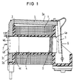
- the magnet system for a relay shown in FIG. 1 has a winding 1 on a coil former 2, and also an angled yoke 3 with a first yoke leg 3a lying approximately parallel to the coil axis and a second yoke leg 3b running perpendicular to the coil axis.
- a core 4 is inserted through the second yoke leg 3b and through the axial recess of the coil body 2, said core facing an armature 5 with a pole end 4a and held non-positively with a fastening end 4b in a bore 3c of the yoke leg 3b is.
- the armature 5 is held with a leaf spring 6, only shown schematically, which also serves as a contact spring. This contact spring works with counter-contact elements, not shown, which are only assembled after the magnet system.
- the core 4 has a consistently round cross-section over most of its length, including the pole end 4a, which is somewhat smaller than the bore 3c in the yoke leg 3b. Only in the area of the fastening end 4b is a conical section 4c formed, which widens conically towards the fastening end with an incline of approximately 1.5 °.
- the core 4 is inserted with its pole end 4a in the direction of arrow 7 first into the bore 3c of the yoke leg 3b and then through the inner bore of the coil former 2, initially requiring little force. Only when the conical section 4c comes into contact with the yoke leg 3b are somewhat higher joining forces required. These joining forces are applied to the fastening end 4b in a pulsed manner with a plunger 8 (see FIG. 2).
- the plunger can impinge in a dome-shaped recess 4d of the core, which at the same time represents a marking for the fastening end of the core; the conical enlargement at this end is so slight that it is not readily recognizable to the naked eye.
- the core In the vicinity of the pole end 4a, the core also has nose-like or rib-shaped projections 9, which secure the core and the coil former against axial displacement.
- FIG. 2 schematically shows a device for joining the core and the yoke for a magnet system according to FIG. 1.
- the magnet system from FIG. 1 with the armature 5 already preassembled is accommodated in a tong-shaped holding device 10 between two jaws 11 and 12 in such a way that the coil axis lies horizontally when the holding device 10 has a bearing 12 about an axis of rotation 13 perpendicular to the axial direction of the coil is pivotally mounted.
- a tappet 8 which can be actuated in pulses in the direction of arrow 7 with a drive device (not shown), applies a force pulse to the fastening end 4b of the core 4 each time the drive device is excited, the magnet system with the holding device 10 being able to dodge in the direction of the arrow 14.
- the next force pulse can be applied.
- a damping element 16 can be provided, which limits the deflection of the system and dampens the vibration.
- the actual counterforce is generated by the inertia of the yoke and the coil.
- the coil axis and the axis of rotation do not necessarily have to lie horizontally, but can assume any other positions in the room.
- the position of the pole end 4a of the core or of the armature 5 resting on the pole end can be measured with a measuring probe 17.
- the core can be driven further into the yoke with further force pulses of the same or different intensity.
Landscapes
- Engineering & Computer Science (AREA)
- Physics & Mathematics (AREA)
- Electromagnetism (AREA)
- Power Engineering (AREA)
- Manufacturing & Machinery (AREA)
- Electromagnets (AREA)
- Resistance Welding (AREA)
Applications Claiming Priority (3)
| Application Number | Priority Date | Filing Date | Title |
|---|---|---|---|
| DE4122705A DE4122705C1 (OSRAM) | 1991-07-09 | 1991-07-09 | |
| DE4122705 | 1991-07-09 | ||
| PCT/DE1992/000512 WO1993001607A1 (de) | 1991-07-09 | 1992-06-22 | Elektromagnetsystem sowie verfahren und vorrichtung zum fügen von kern und joch bei dem elektromagnetsystem |
Publications (2)
| Publication Number | Publication Date |
|---|---|
| EP0593517A1 EP0593517A1 (de) | 1994-04-27 |
| EP0593517B1 true EP0593517B1 (de) | 1995-08-23 |
Family
ID=6435762
Family Applications (1)
| Application Number | Title | Priority Date | Filing Date |
|---|---|---|---|
| EP92912458A Expired - Lifetime EP0593517B1 (de) | 1991-07-09 | 1992-06-22 | Elektromagnetsystem sowie verfahren und vorrichtung zum fügen von kern und joch bei dem elektromagnetsystem |
Country Status (7)
| Country | Link |
|---|---|
| US (1) | US5519369A (OSRAM) |
| EP (1) | EP0593517B1 (OSRAM) |
| JP (1) | JPH06509438A (OSRAM) |
| AT (1) | ATE126929T1 (OSRAM) |
| CA (1) | CA2113096A1 (OSRAM) |
| DE (2) | DE4122705C1 (OSRAM) |
| WO (1) | WO1993001607A1 (OSRAM) |
Cited By (1)
| Publication number | Priority date | Publication date | Assignee | Title |
|---|---|---|---|---|
| DE19726055C1 (de) * | 1997-06-19 | 1998-11-12 | Siemens Ag | Elektromagnetsystem und Verfahren zum Fügen von Kern und Joch in einem solchen System |
Families Citing this family (6)
| Publication number | Priority date | Publication date | Assignee | Title |
|---|---|---|---|---|
| US5905422A (en) * | 1996-11-26 | 1999-05-18 | Siemens Electromechanical Components, Inc. | Relay adjustment structure |
| JP3590738B2 (ja) * | 1999-04-27 | 2004-11-17 | Necトーキン株式会社 | 電磁継電器およびその調整方法と組立方法 |
| DE10304675B4 (de) * | 2002-02-07 | 2009-08-20 | Tyco Electronics Amp Gmbh | Schaltrelais mit einer Magnetspule und Verfahren zum Herstellen eines Schaltrelais |
| JP4803206B2 (ja) * | 2008-04-24 | 2011-10-26 | パナソニック電工株式会社 | リレー用電磁石 |
| CN103794412B (zh) * | 2014-02-08 | 2016-01-20 | 上海沪工汽车电器有限公司 | 一种电磁继电器及其制造方法 |
| DE102021133231A1 (de) | 2021-12-15 | 2023-06-15 | Knorr-Bremse Systeme für Nutzfahrzeuge GmbH | Elektromagnetische Vorrichtung, sowie Verfahren zum Herstellen einer solchen elektromagnetischen Vorrichtung |
Family Cites Families (5)
| Publication number | Priority date | Publication date | Assignee | Title |
|---|---|---|---|---|
| US2735047A (en) * | 1956-02-14 | Antivibration solenoid structure | ||
| US4109221A (en) * | 1976-12-09 | 1978-08-22 | Emerson Electric Co. | Retaining means for a solenoid assembly |
| DE3148052A1 (de) * | 1981-12-04 | 1983-06-09 | Robert Bosch Gmbh, 7000 Stuttgart | Elektromagnetisches relais und verfahren zu seiner herstellung |
| US4720909A (en) * | 1983-10-31 | 1988-01-26 | Amf Inc. | Method of manufacturing miniature power switching relays |
| US4749977A (en) * | 1984-11-26 | 1988-06-07 | United Technologies Corporation | Coil mounting arrangement and its method of manufacture |
-
1991
- 1991-07-09 DE DE4122705A patent/DE4122705C1/de not_active Expired - Fee Related
-
1992
- 1992-06-22 EP EP92912458A patent/EP0593517B1/de not_active Expired - Lifetime
- 1992-06-22 JP JP5501879A patent/JPH06509438A/ja active Pending
- 1992-06-22 DE DE59203404T patent/DE59203404D1/de not_active Expired - Fee Related
- 1992-06-22 US US08/178,286 patent/US5519369A/en not_active Expired - Lifetime
- 1992-06-22 AT AT92912458T patent/ATE126929T1/de not_active IP Right Cessation
- 1992-06-22 WO PCT/DE1992/000512 patent/WO1993001607A1/de not_active Ceased
- 1992-06-22 CA CA002113096A patent/CA2113096A1/en not_active Abandoned
Cited By (2)
| Publication number | Priority date | Publication date | Assignee | Title |
|---|---|---|---|---|
| DE19726055C1 (de) * | 1997-06-19 | 1998-11-12 | Siemens Ag | Elektromagnetsystem und Verfahren zum Fügen von Kern und Joch in einem solchen System |
| US6300851B1 (en) | 1997-06-19 | 2001-10-09 | Tyco Electronics Logistics Ag | Electromagnet system and method for assembling a core and a yoke in such a system |
Also Published As
| Publication number | Publication date |
|---|---|
| JPH06509438A (ja) | 1994-10-20 |
| WO1993001607A1 (de) | 1993-01-21 |
| US5519369A (en) | 1996-05-21 |
| ATE126929T1 (de) | 1995-09-15 |
| DE59203404D1 (de) | 1995-09-28 |
| CA2113096A1 (en) | 1993-01-21 |
| EP0593517A1 (de) | 1994-04-27 |
| DE4122705C1 (OSRAM) | 1992-07-30 |
Similar Documents
| Publication | Publication Date | Title |
|---|---|---|
| DE102013219878B3 (de) | Elektromagnetisch betätigbare Federdruckbremse sowie Verfahren zur Herstellung derselben | |
| EP0466852B1 (de) | Selbstbohrender befestiger | |
| CH661165A5 (de) | Elektromechanischer wandler mit justierbarem ankerjoch und verfahren zum justieren des ankerjochs. | |
| EP0593517B1 (de) | Elektromagnetsystem sowie verfahren und vorrichtung zum fügen von kern und joch bei dem elektromagnetsystem | |
| DE102013004322B4 (de) | Magnetplatte für einen Linearmotor zum Verhindern einer Fehlausrichtung von Magneten | |
| DE2913090A1 (de) | Befestigungselement mit ankerbolzen und spreizkeil | |
| DE3425079A1 (de) | Mit einer welle verbundener koerper | |
| DE2620269A1 (de) | Elektromagnet | |
| DE2717077C3 (de) | Halterung für einen Klappankermagneten eines Mosaikdruckkopfes | |
| EP0918940A1 (de) | Verbindung zwischen zwei bauteilen | |
| DE4436616C2 (de) | Hubmagnet und Verfahren zu seiner Herstellung | |
| DE3240215C1 (de) | Elektromagnetisches Relais | |
| EP3822526B1 (de) | Baugruppe, ventil und verfahren zum montieren der baugruppe | |
| EP0110133B1 (de) | Elektromagnetisches Relais | |
| DE102004013413A1 (de) | Kraftstoff-Einspritzventil | |
| DE19726055C1 (de) | Elektromagnetsystem und Verfahren zum Fügen von Kern und Joch in einem solchen System | |
| WO2023111019A1 (de) | Elektromagnetische vorrichtung, sowie verfahren zum herstellen einer solchen elektromagnetischen vorrichtung | |
| DE3644151C2 (OSRAM) | ||
| DE4210740A1 (de) | Elektromagnet mit einem Hubanker | |
| DE102022102935B4 (de) | Verbindungsanordnung zum Verbinden eines Pfostens mit einem Rahmenprofil eines Fensters oder einer Türe aus Kunststoff | |
| DE19923393C1 (de) | Elektromagnetisch betätigte Reibungsbremse | |
| EP0392051A1 (de) | Verfahren und Anordnung zum Befestigen eines Zentrierstiftes | |
| EP0287022B1 (de) | Dübel, insbesondere Heizkörperdübel | |
| DE10241838B4 (de) | Haftmagnet | |
| DE3825498C2 (OSRAM) |
Legal Events
| Date | Code | Title | Description |
|---|---|---|---|
| PUAI | Public reference made under article 153(3) epc to a published international application that has entered the european phase |
Free format text: ORIGINAL CODE: 0009012 |
|
| 17P | Request for examination filed |
Effective date: 19930604 |
|
| AK | Designated contracting states |
Kind code of ref document: A1 Designated state(s): AT CH DE FR GB IT LI |
|
| 17Q | First examination report despatched |
Effective date: 19941014 |
|
| GRAA | (expected) grant |
Free format text: ORIGINAL CODE: 0009210 |
|
| AK | Designated contracting states |
Kind code of ref document: B1 Designated state(s): AT CH DE FR GB IT LI |
|
| REF | Corresponds to: |
Ref document number: 126929 Country of ref document: AT Date of ref document: 19950915 Kind code of ref document: T |
|
| REF | Corresponds to: |
Ref document number: 59203404 Country of ref document: DE Date of ref document: 19950928 |
|
| ET | Fr: translation filed | ||
| ITF | It: translation for a ep patent filed | ||
| GBT | Gb: translation of ep patent filed (gb section 77(6)(a)/1977) |
Effective date: 19951106 |
|
| PLBE | No opposition filed within time limit |
Free format text: ORIGINAL CODE: 0009261 |
|
| STAA | Information on the status of an ep patent application or granted ep patent |
Free format text: STATUS: NO OPPOSITION FILED WITHIN TIME LIMIT |
|
| 26N | No opposition filed | ||
| PGFP | Annual fee paid to national office [announced via postgrant information from national office to epo] |
Ref country code: AT Payment date: 19980604 Year of fee payment: 7 |
|
| PGFP | Annual fee paid to national office [announced via postgrant information from national office to epo] |
Ref country code: CH Payment date: 19980911 Year of fee payment: 7 |
|
| PG25 | Lapsed in a contracting state [announced via postgrant information from national office to epo] |
Ref country code: AT Free format text: LAPSE BECAUSE OF NON-PAYMENT OF DUE FEES Effective date: 19990622 |
|
| PG25 | Lapsed in a contracting state [announced via postgrant information from national office to epo] |
Ref country code: LI Free format text: LAPSE BECAUSE OF NON-PAYMENT OF DUE FEES Effective date: 19990630 Ref country code: CH Free format text: LAPSE BECAUSE OF NON-PAYMENT OF DUE FEES Effective date: 19990630 |
|
| REG | Reference to a national code |
Ref country code: CH Ref legal event code: PL |
|
| REG | Reference to a national code |
Ref country code: GB Ref legal event code: 732E |
|
| PGFP | Annual fee paid to national office [announced via postgrant information from national office to epo] |
Ref country code: FR Payment date: 20010531 Year of fee payment: 10 |
|
| REG | Reference to a national code |
Ref country code: GB Ref legal event code: IF02 |
|
| PGFP | Annual fee paid to national office [announced via postgrant information from national office to epo] |
Ref country code: GB Payment date: 20020501 Year of fee payment: 11 |
|
| PGFP | Annual fee paid to national office [announced via postgrant information from national office to epo] |
Ref country code: DE Payment date: 20020628 Year of fee payment: 11 |
|
| PG25 | Lapsed in a contracting state [announced via postgrant information from national office to epo] |
Ref country code: FR Free format text: LAPSE BECAUSE OF NON-PAYMENT OF DUE FEES Effective date: 20030228 |
|
| REG | Reference to a national code |
Ref country code: FR Ref legal event code: ST |
|
| PG25 | Lapsed in a contracting state [announced via postgrant information from national office to epo] |
Ref country code: GB Free format text: LAPSE BECAUSE OF NON-PAYMENT OF DUE FEES Effective date: 20030622 |
|
| PG25 | Lapsed in a contracting state [announced via postgrant information from national office to epo] |
Ref country code: DE Free format text: LAPSE BECAUSE OF NON-PAYMENT OF DUE FEES Effective date: 20040101 |
|
| GBPC | Gb: european patent ceased through non-payment of renewal fee |
Effective date: 20030622 |
|
| PG25 | Lapsed in a contracting state [announced via postgrant information from national office to epo] |
Ref country code: IT Free format text: LAPSE BECAUSE OF NON-PAYMENT OF DUE FEES;WARNING: LAPSES OF ITALIAN PATENTS WITH EFFECTIVE DATE BEFORE 2007 MAY HAVE OCCURRED AT ANY TIME BEFORE 2007. THE CORRECT EFFECTIVE DATE MAY BE DIFFERENT FROM THE ONE RECORDED. Effective date: 20050622 |