EP0593483B1 - Apparat zur dehnungsüberwachung und verfahren zur anwendung in mechanischen strukturen, die einer spannung ausgesetzt sind - Google Patents
Apparat zur dehnungsüberwachung und verfahren zur anwendung in mechanischen strukturen, die einer spannung ausgesetzt sind Download PDFInfo
- Publication number
- EP0593483B1 EP0593483B1 EP91918771A EP91918771A EP0593483B1 EP 0593483 B1 EP0593483 B1 EP 0593483B1 EP 91918771 A EP91918771 A EP 91918771A EP 91918771 A EP91918771 A EP 91918771A EP 0593483 B1 EP0593483 B1 EP 0593483B1
- Authority
- EP
- European Patent Office
- Prior art keywords
- strain
- piece
- structural member
- phase
- measuring
- Prior art date
- Legal status (The legal status is an assumption and is not a legal conclusion. Google has not performed a legal analysis and makes no representation as to the accuracy of the status listed.)
- Expired - Lifetime
Links
- 238000000034 method Methods 0.000 title claims abstract description 33
- 238000012544 monitoring process Methods 0.000 title abstract description 10
- 239000000463 material Substances 0.000 claims abstract description 109
- 230000008859 change Effects 0.000 claims abstract description 77
- 230000005294 ferromagnetic effect Effects 0.000 claims description 35
- 230000005291 magnetic effect Effects 0.000 claims description 30
- 238000001514 detection method Methods 0.000 claims description 22
- 230000004044 response Effects 0.000 claims description 16
- 229910000851 Alloy steel Inorganic materials 0.000 claims description 12
- 230000015556 catabolic process Effects 0.000 claims description 12
- 238000006731 degradation reaction Methods 0.000 claims description 12
- 238000000576 coating method Methods 0.000 claims description 9
- 239000000126 substance Substances 0.000 claims description 8
- 239000011248 coating agent Substances 0.000 claims description 7
- 230000002427 irreversible effect Effects 0.000 claims description 5
- 230000003938 response to stress Effects 0.000 claims description 2
- 239000000956 alloy Substances 0.000 abstract description 33
- 229910000794 TRIP steel Inorganic materials 0.000 abstract description 30
- 229910045601 alloy Inorganic materials 0.000 abstract description 30
- 238000005259 measurement Methods 0.000 abstract description 25
- 239000012782 phase change material Substances 0.000 abstract description 14
- 230000006698 induction Effects 0.000 description 16
- 230000005307 ferromagnetism Effects 0.000 description 13
- 230000006835 compression Effects 0.000 description 11
- 238000007906 compression Methods 0.000 description 11
- 239000000758 substrate Substances 0.000 description 11
- XEEYBQQBJWHFJM-UHFFFAOYSA-N Iron Chemical compound [Fe] XEEYBQQBJWHFJM-UHFFFAOYSA-N 0.000 description 10
- 229910000831 Steel Inorganic materials 0.000 description 7
- 239000010959 steel Substances 0.000 description 7
- 238000010276 construction Methods 0.000 description 6
- 239000011159 matrix material Substances 0.000 description 6
- 238000004364 calculation method Methods 0.000 description 5
- 229910052742 iron Inorganic materials 0.000 description 5
- 239000007787 solid Substances 0.000 description 5
- 230000009466 transformation Effects 0.000 description 5
- 230000008901 benefit Effects 0.000 description 4
- 238000006073 displacement reaction Methods 0.000 description 4
- 230000035945 sensitivity Effects 0.000 description 4
- 238000005452 bending Methods 0.000 description 3
- 239000013078 crystal Substances 0.000 description 3
- 238000010586 diagram Methods 0.000 description 3
- 230000007613 environmental effect Effects 0.000 description 3
- 230000001939 inductive effect Effects 0.000 description 3
- 239000000203 mixture Substances 0.000 description 3
- 238000003860 storage Methods 0.000 description 3
- PXHVJJICTQNCMI-UHFFFAOYSA-N Nickel Chemical compound [Ni] PXHVJJICTQNCMI-UHFFFAOYSA-N 0.000 description 2
- 230000002159 abnormal effect Effects 0.000 description 2
- 230000003466 anti-cipated effect Effects 0.000 description 2
- 238000011161 development Methods 0.000 description 2
- 230000018109 developmental process Effects 0.000 description 2
- 238000005516 engineering process Methods 0.000 description 2
- 238000007689 inspection Methods 0.000 description 2
- 239000007788 liquid Substances 0.000 description 2
- 238000012856 packing Methods 0.000 description 2
- 239000002689 soil Substances 0.000 description 2
- 238000012360 testing method Methods 0.000 description 2
- 238000000844 transformation Methods 0.000 description 2
- OKTJSMMVPCPJKN-UHFFFAOYSA-N Carbon Chemical compound [C] OKTJSMMVPCPJKN-UHFFFAOYSA-N 0.000 description 1
- VYZAMTAEIAYCRO-UHFFFAOYSA-N Chromium Chemical compound [Cr] VYZAMTAEIAYCRO-UHFFFAOYSA-N 0.000 description 1
- ZOKXTWBITQBERF-UHFFFAOYSA-N Molybdenum Chemical compound [Mo] ZOKXTWBITQBERF-UHFFFAOYSA-N 0.000 description 1
- 230000002730 additional effect Effects 0.000 description 1
- 238000005275 alloying Methods 0.000 description 1
- 230000004075 alteration Effects 0.000 description 1
- XAGFODPZIPBFFR-UHFFFAOYSA-N aluminium Chemical compound [Al] XAGFODPZIPBFFR-UHFFFAOYSA-N 0.000 description 1
- 229910052782 aluminium Inorganic materials 0.000 description 1
- 238000013459 approach Methods 0.000 description 1
- 238000000429 assembly Methods 0.000 description 1
- 230000000712 assembly Effects 0.000 description 1
- 229910001566 austenite Inorganic materials 0.000 description 1
- 230000004323 axial length Effects 0.000 description 1
- 229910052799 carbon Inorganic materials 0.000 description 1
- 238000012824 chemical production Methods 0.000 description 1
- 229910052804 chromium Inorganic materials 0.000 description 1
- 239000011651 chromium Substances 0.000 description 1
- 239000002131 composite material Substances 0.000 description 1
- 238000007596 consolidation process Methods 0.000 description 1
- 230000009977 dual effect Effects 0.000 description 1
- 230000000694 effects Effects 0.000 description 1
- 238000012854 evaluation process Methods 0.000 description 1
- 238000002474 experimental method Methods 0.000 description 1
- 238000011065 in-situ storage Methods 0.000 description 1
- 238000010348 incorporation Methods 0.000 description 1
- 230000003993 interaction Effects 0.000 description 1
- 239000000696 magnetic material Substances 0.000 description 1
- 230000005415 magnetization Effects 0.000 description 1
- 238000012423 maintenance Methods 0.000 description 1
- WPBNNNQJVZRUHP-UHFFFAOYSA-L manganese(2+);methyl n-[[2-(methoxycarbonylcarbamothioylamino)phenyl]carbamothioyl]carbamate;n-[2-(sulfidocarbothioylamino)ethyl]carbamodithioate Chemical compound [Mn+2].[S-]C(=S)NCCNC([S-])=S.COC(=O)NC(=S)NC1=CC=CC=C1NC(=S)NC(=O)OC WPBNNNQJVZRUHP-UHFFFAOYSA-L 0.000 description 1
- 238000004519 manufacturing process Methods 0.000 description 1
- 229910000734 martensite Inorganic materials 0.000 description 1
- 238000011089 mechanical engineering Methods 0.000 description 1
- 230000007246 mechanism Effects 0.000 description 1
- 238000012986 modification Methods 0.000 description 1
- 230000004048 modification Effects 0.000 description 1
- 229910052750 molybdenum Inorganic materials 0.000 description 1
- 239000011733 molybdenum Substances 0.000 description 1
- 229910052759 nickel Inorganic materials 0.000 description 1
- 230000003287 optical effect Effects 0.000 description 1
- 230000000737 periodic effect Effects 0.000 description 1
- 230000000704 physical effect Effects 0.000 description 1
- 238000012545 processing Methods 0.000 description 1
- 239000002901 radioactive waste Substances 0.000 description 1
- 229910001220 stainless steel Inorganic materials 0.000 description 1
- 239000000725 suspension Substances 0.000 description 1
- 238000011179 visual inspection Methods 0.000 description 1
Images





Classifications
-
- G—PHYSICS
- G01—MEASURING; TESTING
- G01B—MEASURING LENGTH, THICKNESS OR SIMILAR LINEAR DIMENSIONS; MEASURING ANGLES; MEASURING AREAS; MEASURING IRREGULARITIES OF SURFACES OR CONTOURS
- G01B7/00—Measuring arrangements characterised by the use of electric or magnetic techniques
- G01B7/16—Measuring arrangements characterised by the use of electric or magnetic techniques for measuring the deformation in a solid, e.g. by resistance strain gauge
-
- G—PHYSICS
- G01—MEASURING; TESTING
- G01B—MEASURING LENGTH, THICKNESS OR SIMILAR LINEAR DIMENSIONS; MEASURING ANGLES; MEASURING AREAS; MEASURING IRREGULARITIES OF SURFACES OR CONTOURS
- G01B7/00—Measuring arrangements characterised by the use of electric or magnetic techniques
- G01B7/16—Measuring arrangements characterised by the use of electric or magnetic techniques for measuring the deformation in a solid, e.g. by resistance strain gauge
- G01B7/24—Measuring arrangements characterised by the use of electric or magnetic techniques for measuring the deformation in a solid, e.g. by resistance strain gauge using change in magnetic properties
Definitions
- the present invention is directed to the field of measuring and monitoring stress within structures of virtually any type. Examples of such structures, without limitations, include buildings, bridge works, pipelines, dams, roads, aircraft and machinery. In its most general form, however, the present invention is directed to the field of measuring the strain existing between two spaced-apart locations regardless of the medium in which the stress and strain occurs.
- Every mechanical structure is inherently subjected to mechanical stress of one type or another. Where the structure is located in a gravitational field, for example, the mere presence of the gravitational force causes certain strain to be placed upon the component parts of that structure.
- Most physical structures are engineered to withstand such background stress; however, in many environments, it is not unusual for abnormal stresses to be applied to such structures, from time-to-time. These abnormal stresses may come from environmental events, such as earthquakes, but also from the use of the structure, such as a bridge or from operation of the structure, such as a machine, in the normal course of activity.
- buildings receive variable loading conditions as a result of human use, wind currents, vibrations, etc.
- Bridges are subjected to varying loads as a result of traffic thereacross (and the vibrations caused thereby), wind currents and tidal currents, to name a few.
- this structure may be subjected to thermal loads, soil/structure interaction (creep, settlements, and consolidation) and unusual loads caused by earthquakes or other natural disasters.
- Machinery such as ships, aircraft, industrial equipment and the like, encounter varying load forces as a condition of their operation since the machinery normally operates by applying a force to some resistance in order to produce work. Thus, the structural members of machinery must bear the loads caused by the application of the force.
- the present invention concerns measuring strains on structural systems, although the present invention can be used to monitor strain between any two locations susceptible to the attachment of a strain element according to the present invention. Thus, not only can the present invention monitor strain on structural members, but also the present invention can measure dislocation between two points and can monitor strain, for example, in a soil or substrate medium.
- strain gauges as analytical apparatus, has heretofore been known.
- electrical strain gauges have been developed and may be normally grouped into four types: (1) capacitance gauges: (2) inductance or magnetic gauges; (3) piezoelectric gauges; and (4) resistance gauges.
- capacitance gauges (2) inductance or magnetic gauges
- piezoelectric gauges (3) piezoelectric gauges
- resistance gauges (4) resistance gauges.
- the inductance gauge wherein a measurement of strain, as a function in a change in length, occurs by the displacement of an inductive element relative to a conductive coil so as to change the inductance of the electronic circuit resulting in a change in current flow therethrough. This change in current flow creates a strain signal that may then be magnified by any suitable electronic means.
- capacitive strain gauges operate by relative movement of capacitive plates or a dielectric medium to change the capacitance of the system thereby generating a signal indicative of relative movement between the points subjected to strain.
- Resistive strain gauges react to changes in resistance on wires due to strain deformation of the wire.
- Piezoelectric strain gauges operate on the current generation of piezoelectric crystals placed under strain to produce a strain measurement.
- strain gauges In part, this may be due to the high cost of existent strain gauges, but also, these gauges are fairly complex in construction and relatively fragile. Thus, operation and measurement requires a relatively high level of skill, and constant use in situ would likely lead to unacceptably high maintenance and lack of reliability. Accordingly, there remains a need for an improved strain gauge element and strain gauge devices which are relatively inexpensive to produce and easy to use and operate.
- a device for measuring mechanical strain on a structural member comprising:
- the present invention thereby provides a new and useful strain gauge element formed of a material so that the strain gauge uses a different physical phenomenon as an indicator of strain in a structure.
- the present invention further provides a new and useful method for measuring strain in a structure resulting from stress.
- the present invention also provides apparatus and methodology wherein strain on a structural system may be measured by observing a phase change in a material forming a strain gauge element.
- the present invention further provides apparatus and methodology wherein structural members or components in a structural system may be fabricated, in whole or in-part, utilizing a material that under goes a phase change from a non-ferromagnetic state to a ferromagnetic state in response to strain.
- the present invention also provides an apparatus and method for measuring peak strain on a structure over an interval of time.
- An advantage of the present invention is to provide a monitoring system for structures that is non-comsumptive in power yet which may be interrogated to provide measurement of the degradation of the structure due to stress.
- the device in its broad form, includes a piece of material formed out of a substance which changes phase in response to stress.
- This piece of material is secured to a structural element, for example, in a structural system, by appropriate mounts so that relative movement between the two mount locations resulting from stress on the structure places strain on the piece of material. Instrumentation for the measurement of the phase change is then provided so that the degree of phase change may be used to calculate a strain, and therefore the degree of degradation, in the structural member.
- the strain element according to the preferred embodiment of the present invention utilizes material which changes phase, and hence its magnetic properties in response to strain.
- a strain element is formed out of a transformation induced plasticity (TRIP) alloy steel which, as is known, under goes an irreversible change from a non-ferromagnetic to a ferromagnetic state proportionally in response to strain.
- TRIP transformation induced plasticity
- This strain element is preferably a tensile element which, for example, may be mounted between a pair of mounts so that relative movement of the mounts places tension on, and thus stretches, the tensile element causing the TRIP steel alloy to increase its ferromagnetic property.
- a coil surrounds the tensile element and measurement of the magnetic inductance is accomplished by measuring current through the coil.
- a web-like array of TRIP wires may be embedded in the skin of a structure, such as an airplane wing, and the magnetic inductance may be measured by an independent coil placed in proximity to the web-like material.
- the TRIP element may be a plate or coating on a structural element and the change in magnetic inductance measured by any convenient instrument, as known in the art.
- the strain element may be a structural member of the structural system or may be an auxiliary element attached to the structure. In the former case, for example, the strain element may be a wire, cable, plate, beam, column or other structural member and can likewise be a fastener, such as a screw, bolt, rivet, and the like, used to connect two structural members together.
- strain gauges according to the present invention can measure a single strain resulting, for example, from compression or tension.
- strain gauges can be constructed to measure strains in multi-dimensions, for example, as would result from combined normal and shear stressing.
- the present invention may be incorporated in virtually any type of structure, including machinery, which is subjected to stress.
- the method and apparatus of the present invention may be used in such diverse areas as bridges and roadways, dams, buildings, pipelines and machinery, such as airplanes or large industrial equipment to name a few.
- phase changing tensile elements and strain gauges which incorporate these tensile elements may be integrated into a system that is operative to measure strain on structural members joined together in an integrated structure.
- a plurality of detection elements are disposed at selected locations throughout the structure and are connected to the structural members so that stress on each respective structural member strains the phase change material in its respective detection element. This phase change is measured by any convenient method.
- some of the detection elements may be connected to this structure at monitor points to defined dislocation monitor elements for registering relative dislocation between the monitor points. Other detection elements may actually measure strain on specific structural members, as selected.
- the detection elements may be embedded in a structure, such as a roadway or dam as a means for mounting the detection element to the structure. Deformation of the structure may thus be monitored in two or three dimensions over a time interval.
- the phase change measuring instrumentation may be a detector located externally of the structural members or may be an on-site instrumentation. In either event, it is preferred that the strain gauges of the system be linked to a central monitor station. In either event, the instrumentation generates an interrogation signal that is transmitted to each detector element, with this interrogation signal being of such character as to be affected by phase changes in the material of the respective detection element so that, as a modified signal, it may be received by the instrumentation which generates output indicative of the phase change of the detection element. This modified signal may be processed to generate a calculation of the strain occurring at the respective detection element. If desired, this output may be used to generate an alarm signal indicative of an unsafe condition for the structure.
- the broad method of the present invention measures strain in a structure and incorporates several basic steps.
- a piece of material formed of a substance which undergoes a change in phase in response to strain is incorporated into a structure in a manner such that the piece of material will be strained correspondingly to the strain to be measured in the structure.
- the phase change in the material is measured as an indicator of the strain resulting therefrom.
- the piece of material may be incorporated as a structural member, the piece of material may be embedded into the structure or the piece of material may be attached as an auxiliary element on a structural member.
- the piece of material is configured as a tensile element so that the step of incorporating the element into the structure may be accomplished by providing spaced-apart anchors to secure opposite ends of the tensile element or by embedding the element in the structure.
- the material is preferably one which changes phase from a non-ferromagnetic state to a ferromagnetic state in response to strain and the step of measuring is accomplished by measuring a change in the magnetic inductance of the material.
- the present invention concerns the measurement of strain in various structures.
- the present invention in its broad form, includes new and useful strain detection elements which may be formed into independent strain gauges that are mountable to a structural member and which may be monitored to measure a strain of that particular member.
- the strain detection elements may be incorporated into the structure, either as primary or secondary structural members or by being embedded into the body of the structural member.
- the invention therefore contemplates a measurement system which may be integrated into large structures so as to be used in monitoring numerous strain locations within that structure.
- the present invention is also directed to new and useful methodologies for measuring the strain in a structural member and in complex structures comprising large structural members or numerous structural members.
- a representative structural member 10 longitudinally extends between a first location X 1 and a second location X 2 , the structural member 10 may be subjected to an axial tension force T, shown in Figure 1(a), or a compression force C, shown in Figure 1(b). In either event, structural member 10 may be subjected to a transverse shear force S.
- X 1 -X 2 it may be appreciated that there are therefore two stresses, an axial stress and a shear stress, with stress being defined as force per unit area as is well known in the mechanical arts. Since, in reality, a structural member is three dimensional, there are therefore six different stresses which may act on the three dimensional object.
- Mechanical strain is a natural result of stresses on the material. Normal strain is measured as a percentage change in length of the material in the dimension being measured. Thus, by way of illustration, if an axial stress causes a doubling in the length of an axial element to which it is applied, then that element has 100% axial or normal strain. Similarly, if the axial force is compression, and the stress results in a decrease to 1/2 of the original axial length, the material has been -50% strained.
- the ability to measure the strain on the material allows the calculation of degradation of the strained member and, by knowing the properties of the member itself, allows calculation of the stress which resulted in the strain, all as is well known in the field of mechanical engineering. Accordingly, for a known structural member, knowledge of the stress allows calculation of the strain or, alternately, knowledge of the strain allows calculation of the stress.
- strain gauges As noted in the background section of this invention, there have been several different varieties of strain gauges developed in the past for purposes of measuring the strain on a member since it is often more convenient to measure strain as opposed to measuring stress. These devices have accomplished strain measurement by the relative movement of a ferromagnetic core with respect to measurement coils, the relative movement of capacitive plates or dielectric media, the change in the electrical resistance resulting from strain deformation or the production of electric current from a piezoelectric device undergoing strain.
- the present invention adds what is believed a revolutionary fifth technique to the four techniques described in the prior art, namely, the change in phase of a strained material.
- the preferred embodiment of the present invention relies on a measurement of magnetic inductance similar to the induction type gauges; however, the physical mechanism (phase change) for the relative change in magnetic induction is entirely different from that heretofore utilized in strain gauges.
- gauges made according to the teachings of the present invention may therefore be termed to be phase change gauges.
- phase change in its broadest form, is simply the alteration of a physical property of the material from one state to another.
- a change in phase may occur between solid to liquid, liquid to gas or solid to gas.
- a phase is commonly defined as a uniform, homogeneous body of matter which is physically distinct from other such bodies of matter.
- the atoms comprising the material are arranged in a specific periodic array known as the lattice. The properties exhibited by a crystalline solid depend on the particular three-dimensional array or "crystal structure" assumed by the atoms.
- the present invention contemplates that a different phase change in materials may be incorporated into strain gauges or used to provide strain detecting elements
- the primary material currently recognized by the inventors that is particularly useful as a strain element is that material known as transformation induced plasticity alloy steel which is known by its acronym TRIP alloy steel.
- Some solids can exist in more than one atomic arrangement, depending on the temperature, pressure, or other environmental influences.
- the stable form of iron, under ambient conditions, is body-centered-cubic; however, by alloying iron with other elements, the atoms can exist in metastable crystal structures such as face-centered-cubic.
- materials which existed in the metastable face-centered-cubic atomic orientation would transform to a more stable arrangement under the influence of applied stress (or strain). As a result the deformation characteristics of these materials were found to be unique in their combinations of attainable strength with fracture resistance, or toughness.
- TRIP alloy steels are iron-based alloys which may contain elements such as manganese, carbon, nickel, chromium and molybdenum (to list a few).
- TRIP alloyed steels were developed specifically for their higher strength and toughness plus their potential for producing structural members of greater strength per unit weight. While the magnetic properties of TRIP alloy steels were noted and the ability of these materials to change phase was noted, there simply was no interest exhibited historically in this feature apart from their strength. While these materials were investigated briefly as a potential material within which to encase radio-active wastes, this technology never developed. Thus, there has been virtually no application of these materials other than as high strength and high toughness structural elements.
- TRIP steel alloys are in a face centered cubic phase when in an unloaded state. That is, each unit cell in the crystalline structure has an atom located at the corner of a cube and another atom centered on each face of the cube. This phase is metastable and is different from the normal atomic packing of iron-based alloys which is body-centered-cubic in their stable phase. "Body-centered-cubic" is an atomic packing wherein each unit cell has an atom located on the corner of the cube with another atom being located in the center of the cubic cell.
- TRIP steel alloys change phase from an unloaded or virgin state wherein the phase is the metastable face-centered-cubic structure to the stable body centered cubic structure in proportion to the amount of loading on an element constructed of TRIP steel alloy.
- This phase change has two properties which allow the material particular utility in strain measurement apparatus and methodology. First, the change in phase from the face centered cubic structure to the body centered cubic structure causes a resulting change in the magnetic property of the material, namely, from being non-ferromagnetic to becoming ferromagnetic. Second, this phase change is irreversible.
- the virgin loading curve L indicates that strain and stress are proportional to one another.
- the percentage of ferromagnetism M f is a function of strain and, that the composition of the particular alloy may be constructed so as to shift the ferromagnetic curve so that different ranges of strain may be measured by different alloyed composition thus revealing that different materials will exhibit different sensitivities and responses.
- a first ferromagnetic curve M 1 has a dynamic range between strain s 1 and s 3 within which the percentage of ferromagnetism may be used to measure the strain on the material.
- ferromagnetic curve M 2 a dynamic range between strain s 1 and s 3 within which the percentage of ferromagnetism may be used to measure the strain on the material.
- ferromagnetic curve M 3 has a dynamic range corresponding to measurable strain range between s 4 stand s 6 . Because of the overlap of the dynamic ranges of the curve M 1 , M 2 and M 3 it may be seen that for the three elements graphed in Figure 2(b), the respective ferromagnetic percentages of the three elements provide a dynamic range extending of measurable strain between points s 1 and s 6 .
- Applicants have recognized that the change from a non-ferromagnetic state to a ferromagnetic state over the respective detectable ranges can be utilized to measure strain in an easy, inexpensive manner which has heretofore not been recognized. Also, that different strain elements may be tailored by the composition of the alloys to create strain elements of differing sensitivities having different measurable strain ranges which may be used alone or in combination to create strain gauges having a desired sensitivity. Finally, since the change from the non-ferromagnetic state to the ferromagnetic state is irreversible, strain elements constructed of TRIP steel alloys have a secondary benefit of being able to measure peak strain that has occurred on the element due to stress deformation even if subsequent opposite stress deformations return the element to its original configuration.
- the TRIP steel alloy element nonetheless will allow measurement of the maximum strain to which the element was previously subjected. This, in turn, has significant benefits in apparatus and methodologies of measuring the strain on various structures.
- FIG 3 the fundamental form of the present invention wherein a strain element 20 extends between locations X 1 and X 2 , similarly to the member 10 in Figures 1(a) and 1(b).
- Strain element 20, according to the present invention is formed of a selected TRIP steel alloy of the type described above.
- Coil 22 of a wire 24 is wrapped around element 20 and is connected to a magnetic induction meter 26 which may detect the magnetic inductance of element 20.
- the magnetic induction for coil 22 changes.
- element 20 forms a core for coil 22 which core changes in ferromagnetic properties proportionally to strain.
- the change in ferromagnetism of the core correspondingly and proportionally changes the magnetic induction of coil 22, as is well known, which may be measured by magnetic induction meter 26.
- meter 26 can readily be calibrated so that it measures the percentage ferromagnetism in element 20 and thus the strain thereon.
- This strain element 20 thus suggests devices which may be used to measure strain on a structural member.
- a cable 30 is represented which may under go a tension as a stress.
- a TRIP steel alloy element in the form of a TRIP wire 40 is mounted between a first mount 42 and a second mount 44 that are secured to cable 30 so that any stretching of cable 30 causes mounts 42 and 44 to move apart from one another.
- Relative movement of mounts 42 and 44 causes a stretching of wire 40 by virtue of its attachment points 46 and 48 so that wire 40 is strained directly proportionally to the strain on cable 30 due to axial tension.
- the magnetic induction through coil 43 may be measured by meter 47 so that strain on cable 30 may be directly measured.
- FIG. 5 shows a TRIP steel alloy connector 50 being used as a secondary structural member to interconnect primary structural members in the form of cables 52 and 54.
- the TRIP steel alloys have high strength properties for which they were initially developed, they may be used as connectors or fasteners to interconnect primary structural members together and measure the strain occurring on the combined structural system, for example, cables 52 and 54.
- structural element 50 is affixed by mounts 56 and 58 to cable ends 53 and 55, respectively, with element 50 having a central portion 60 of reduced dimension which is encompassed by a coil 63 of wire 65 connected to meter 67.
- Axial deformation of central portion 60 in the form of lengthening due to tension on cables 52 and 54 results in the change in phase of central portion 60 which may be monitored by induction metering and induction measuring instrument 67, as described above.
- TRIP steel alloy material itself may constitute a primary structural member so that, as is shown in Figure 6, a cable 70 may itself be constructed entirely of TRIP steel alloy. Where the TRIP alloy steel is used as the primary structural member, it is simply a matter of providing a wire coil 73 connected to meter 77 to measure the relative percentage of ferromagnetism in cable 70 to determine the strain on cable 70 resulting from tension stresses. Similarly, it may be seen that, in Figure 7, a cable 80 may be constructed of multiple strands 81, 82 and 83, one or more of which may be a strand of TRIP steel alloy cable.
- Cable 80 comprises a primary structural member the strain on which may be measured by an instrument 87 connected to coil 85 which encircles cable 80.
- instrument 87 connected to coil 85 which encircles cable 80.
- each of strands 81, 82 and 83 may be constructed to have slightly different response curves to strain so that a wide range of strain may be measured by construction strands 81, 82 and 83 to have overlapping ferromagnetic curves.
- any of the TRIP steel elements such as shown in Figures 4-7, may be incorporated into a system for measuring strain on an integrated structure.
- a bridge 90 is shown which includes a bed 92 that is supported by a plurality of cables 93-97 from a suspension cable 98.
- cables 93-97 have a corresponding strain gauge element 103-107 and cable 98 is provided with a strain gauge element 108.
- each of the respective cables may be measured for strains resulting from normal use of bridge 90 or resulting from unusual environmental strains that may result, for example, from high winds, earthquakes, and the like.
- These cables may be monitored for a selected degradation factor and, since the change in phase of TRIP alloy steels is irreversible, each of the strain gauge elements 103-108 measure the peak strain which occurs over an interval of time.
- each of gauges 103-108 could be monitored by a common remote sensor instrument which may poll the respective strain gauge element to determine the strain on its respective support cable.
- a strain measuring instrument it is not necessary for a strain measuring instrument to be in one-to-one correspondence with the number of strain gauge elements.
- the strain measuring instrument it is not necessary that the strain measuring instrument be locally integrated either with each respective strain gauge or with the ensemble of strain gauge elements 103-108. Rather, an independent portable meter may readily used by a technician to read the condition of cables 93-98 since the strain elements are passive. This provides the natural advantage of no power consumption except at such time that a strain measurement is being performed.
- FIG. 8 The technique noted with respect to Figure 8 may also be used for example, with a structure 110 wherein a first horizontal member 112 is mounted for suspended support from a second horizontal member 114 by a pair of support bolts 116.
- Each bolt 116 has a head structure 118 and a shaft structure 120 which extends through passageways 122 in support 114 and 124 in support 112.
- Bolts 116 are secured at an end opposite head structures 118 by means of nut structures 126.
- Tension on bolts 116 due to gravitational or other loading on horizontal support 112 with respect to support 114 may be monitored when bolts 116 are formed of a TRIP alloy steel.
- coils 125 encircle a selected portion of bolt 116 so that magnetic induction may be monitored by a measuring instrument 127.
- phase change devices in the form of a TRIP steel wire or cable segment. That is, it is more convenient to measure the strain produced by axial tension due to the elongation of a TRIP steel alloy wire than measuring the compression on such a wire since the wire may buckle before fully straining under compression.
- the phase change TRIP steel alloy wire may sometimes hereinafter be referred to as a tensile element, and these tensile elements may be used to measure both the strains on structural members, such as support columns, beams and struts, due to stress. These strains measured may be both positive and negative strains resulting respectively from tension and compression.
- tensile elements 131, 132 and 133 may be mounted between first and second mounts 134 and 136 which are affixed to a portion of structural member 140.
- Each of tensile elements 131-133 has associated therewith a respective coil 137, 138 and 139. Any elongation of member 140 which causes movement of mounts 134 and 136 apart from one another places stress in the form of tension on tensile elements 131-133 so that any elongation of tensile elements 131-133 is representative of the strain on structural member 140.
- Tensile elements 131-133 can be constructed so as to measure different ranges of strain, as described above.
- structural member 140 may be monitored for strain resulting from compression by means of the strain device 150 wherein a pair of mounts 152 and 154 are provided and are affixed to structural member 140.
- Mounts 152 and 154 are constructed in any convenient manner so that relative movement of mounts 152 and 154 toward one another creates tension on tensile elements 171, 172 and 173.
- mount 152 has a base portion 156 to which a crossbar 158 is rigidly secured by arms 160.
- An opening 162 is formed in crossbar 158 which slideably receives arm 164 which is rigidly secured to base 166 of mount 154.
- Opposite mount 154 is formed a T-shaped crossbar 168 which is rigidly secured to arm 164 so that, when base portions 156 and 166 move toward one another, under compressive forces, crossbar 158 and T-shaped crossbar 168 separate from one another to elongate tensile elements 171-173 so that the corresponding ferromagnetic phase change may be measured by coils 174-176 associated therewith.
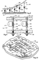
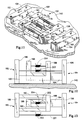
- FIG. 12-14 A dual stage strain gauge, according to the present invention, is shown in Figures 12-14, which is an incorporation of the structures shown in Figures 10 and 11 into a single unit.
- a pair of mounts 182 and 184 are secured to structural member 140.
- Mount 182 has a base 186 and a crossbar section 188 rigidly secured thereto by arms 190.
- mount 184 has a base 196 and a crossbar section 198 which is rigidly secured thereto by means of arm 194.
- a first tensile element 201 extends directly between base portion 186 of mount 182 and base portion 196 of mount 184.
- a second tensile element 202 extends between crossbars 188 and 198.
- Tensile element 201 has an associated coil 203 while tensile element 202 has an associated wire coil 204 for purposes of measuring the change in ferromagnetism thereof by means of the change in magnetic inductance as described above.
- tensile element 201 is elongated thereby monitoring strain induced by tension forces whereas compressive forces place tension on tensile element 202 so that the elongation thereof measures strain due to the compressive forces on structural member 140.
- strain gauge 180 may be mounted to a primary structural member such as I-beam 210, for example, on flange portion 212 thereof. It should be appreciated, however, that gauge unit 180 could be mounted to central web 214 or to any other convenient portion of a beam 210. Where a structure is formed out of a plurality of beams, as is shown in Figure 15, the various strain gauge units 180 may be provided to monitor the structure 220. Here, it may be seen that structure 220 includes a plurality of columns, such as columns 230 which-support beams such as representative beam 240 that may also be supported by struts, such as struts 250. Arrows A 1 -A 5 show the relative compressive and tension forces which would normally be exerted on structure 220 and which may be monitored by strained gauge units of 180 mounted at convenient locations thereon.
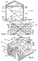
- Figures 16-20 show elements for measuring strain on plates, skins and shells which typically will allow for measuring strains resulting from more than simple one-directional forces. Important to these types of elements, and the methodology contemplated herein, is the fact that it is not necessary to encompass or to encircle the phase change material with a wire coil. Rather, an induction measuring coil may non-intrusively measure the ferromagnetism of a TRIP steel alloy plate, skin, coating or web simply by being placed in sufficient proximity thereto, depending on the sensitivity of the induction measuring instrument. Thus, for example, as is shown in Figure 16, a plate 300 of TRIP steel alloy material may be secured, for example, by bolts 302 to the surface 312 of a structural member 310.
- An electromagnetic wire coil 320 may then selectively be placed in proximity to plate 300 and the ferromagnetic induction measured by means of instrument 330. Any changes to the ferromagnetic property of plate 300 may be monitored by instrument 330 to read the strain on plate 300 resulting from strain on structural member 310.
- instrument 330 to read the strain on plate 300 resulting from strain on structural member 310.
- strains resulting from on structural member 310 due to stress forces which either compress, expand or deflect plate 300 may be monitored.
- the deflective forces are graphically shown by arrows A 6 and A 7 .
- Plates, such as plates 300 can either be attached to a structural member, such as a masonry wall, a structural support panel and the like.
- the TRIP alloy steel materials can even be used to construct a shell such as shell 350.
- shell 350 is shown to comprise an upper panel section 352 and a lower panel section 354 that enclose an interior 356.
- This shell 350 may be formed entirely out of a TRIP steel alloy or, as is shown in Figure 19, a panel may be formed by a substrate 360 with a TRIP alloy steel coating 362.
- a panel 370 may have an embedded web-like matrix 372 of TRIP steel wires, such as wires 374 and 376.
- Web-like matrix 372 may be may be embedded in or attached alongside the surface of an aluminum or composite shell or skin such as in an aircraft wing, boat hull, storage tank and the like.
- Strains resulting from compression, tension, deflection and other deformation forces may then be monitored by measuring the changes in the ferromagnetism of the shell 350, the coating 362, or the web like matrix 370, similarly to the measurement of the change in ferromagnetism of plate 300. It should further be appreciated that, even where a plate or web like matrix is embedded in the structural member, the change in ferromagnetism thereof may be measured non-intrusively through the material by means of an inductive coil placed in proximity to the surface of the structural member. Also, since the TRIP alloy steel has high strength and toughness, the material itself lends strength to the structural material. However, where some flexibility of the structural member is desired, for example, in an aircraft wing, it is envisioned that either the web-like wires shown in Figure 20 or a relatively thin coating such as shown in Figure 19 will be the preferred construction.
- the tensile elements according to the present invention may also be incorporated into a monitoring system that is operative to measure strain on structural members which are joined together as an integrated structure in order to monitor the integrity of the structure for degradation resulting from stress.
- the monitoring of a plurality of structural members interconnected as a structure was discussed, somewhat, with reference to Figure 15. In that figure, a plurality of strain gauges 180 were placed on different structural members to monitor stress induced deformations.
- a representative frame structure 400 is shown and includes a substrate or foundation 402 on which is erected a pair of vertical sidewalls 404, a top wall 406 and a roof structure 408. Deformation of the structure, in two-dimensions, as opposed to the strain on any particular structural element, may be monitored by a pair of tensile elements 410 and 412. Tensile element 410 is connected by means of cable sections 420 and 422 to opposite corners 424 and 426 of structure 400.
- tensile element 412 is connected by cable sections 430 and 432 to opposite corners 434 and 436 of structure 400. Any deformation of the rectangular cross-section defined by foundation 402, sidewalls 404 and top wall 406 will result in an axial stress on one of tensile elements 410,412. This axial stress in turn, will strain the phase change material comprising the tensile element, as described above, so that the amount of phase will be indicative of the stress. Therefore, by knowing the original dimensions of the system, not only can the strain event be discovered, but also the magnitude of dislocation between anchor points 425, 427 and between anchor points 435 and 437 may be determined.
- a masonry wall 450 is shown wherein a pair of tensile elements 460 and 462 are connected to diagonal anchor points.
- tensile element 460 is mounted by a cable segment 470 to anchor block 474 by an anchor 475.
- a second cable segment 472 anchors tensile element 460 to anchor block 476 by way of anchor 477.
- Tensile element 462 includes a cable segment 480 which anchors one side of tensile element 462 to anchor block 486 by means of anchor 487, and cable segment 482 anchors tensile block 462 to anchor block 484 by means of anchor 485.
- any deformation of masonry wall 450 will cause a shift in the blocks 474, 476, 484 and 486, and the shift will place stress on one or both tensile elements 460,462. This stress induces a strain that is again quantified by the amount of phase change in the material forming tensile elements 460,462.
- Figure 23 shows a representative integrated structure 500 which may be, for example, a dam or other large concrete work, road bed or substrate medium.
- a matrix of rebar is provided which is cast into the concrete.
- rebar matrix 510 includes longitudinal rebars 512, transverse rebars 514 and vertical rebars 516.
- Strain gauge elements 520 may be mounted on selected ones of these rebars so that three-dimensional stress may be monitored by the strains on the rebar elements.
- the rebars 512, 514 and 516 could, themselves, be constructed of a TRIP steel alloy so that it would simply be necessary to encircle a portion of the rebar element by a wire coil similar to that shown in Figure 5 to monitor the status of the phase change material. This can be accomplished by wiring an external magnetic induction measuring instrument to the coils. Alternately, where rebars 512, 514 and 516 are not produced from phase change material, a tensile gauge, such as shown in Figure 4, may be used to monitor strain on the respective rebars, with such tensile elements being mounted to the selected rebar elements in any convenient manner.
- anchors 551-558 may be cast within structure 500 with these anchor points being connected, as desired, by cable structures such as cables 561-570.
- cable structures such as cables 561-570.
- each of these cables may be provided with tensile elements, similar to those shown in Figures 21 and 22, or cables 561-570 can be constructed by phase change material and provided with the magnetic induction coil or other phase change measurement device. The system shown in Figure 23 would thus allow determination of three-dimensional deformations caused by strain on structure 500.
- Figure 24 shows a system operative to measure phase change on a structure, such as a building 600.
- a central monitor station 610 is provided that is connected by a wires 611-615 to a plurality of tensile strain gauge elements 621-625.
- These monitors 621-625 can be simple tensile elements cast, for example, in columns 631, 632 and 633 but can also be gauged rebars, strain gauges such as strain gauges 180 shown in Figure 15, or any other type of strain gauge encompassed within this invention.
- Central monitor station 610 may include instrumentation to monitor strain on the various strain gauges or tensile elements.
- an alarm 650 can be provided to produce an audible alarm if a selected threshold strain is reached.
- central station 610 could provide a simple junction box for the wiring ensembles connected to the tensile elements or strain gauges. In this embodiment, a technician would simply bring instrumentation to central station 610 and electrically connect the instrumentation to poll the ensemble of strain gauge elements.
- the system would be an active system that would be power consumptive, but, in the second embodiment of this system the system would be passive and only consume power when the technician polled the ensemble of strain gauge elements. Accordingly, after a natural disaster, a technician or engineer could quickly ascertain the integrity of the building, despite the lack of power and regardless of the presence of visible indications of damage. This would be done simply by connecting suitable instrumentation at central monitor station 610. Since each of the tensile elements monitor peak strain, degradation of the structure 600 would be registered despite the fact that the building had been returned to somewhat its original state.
- a pipe 700 has a sidewall 702 in which is embedded a plurality of longitudinal TRIP steel wires 710 located at equidistantly spaced circumferential locations around the longitudinal axis Z. Any stretching or bending of pipe 700 would result in placing tension on one or more of wires 710 which, due to their construction of TRIP alloy steel or other phase change material, would result in a phase change that would be detectable with suitable instrumentation. Where the phase change of wires 710 is one from a non-ferromagnetic state to a ferromagnetic state, a magnetic induction coil could be placed along the circumferential surface 704 of pipe 700 and localized regions of degradation determined.
- a pipe 720 has a first mount 730 and a second mount 732 secured circumferentially therearound.
- a piurality of tensile elements, such as TRIP steel wires 740 are mounted between mounts 730 and 732 so that any strain on wires 740, caused by the stress from bending or elongating pipe 720 would be measured by the change in magnetic inductance of wires 740 by means of inductive coil 742.
- a pipe 720 may be provided with a torque measuring device comprising a pair of mounts 750 and 752.
- a tensile element 760 extends between arms 754 and 756 of mount 750 and, arm 758, attached to mount 752, connects to a central portion of tensile element 760.
- any torque forces caused by relative rotation, shown by arrows A 8 and A 9 will strain tensile element 760 the phase change of which will again be monitored by coil 762.
- torque or twisting forces can be monitored for pipe 720.
- the method according to the preferred embodiment of the present invention contemplates a method of measuring strain in a structure, which may broadly include a substrate media, where the strain results from stress on the system, comprises two general processing steps. First, a piece of material is incorporated into the structure or substrate wherein the piece of material is formed of a substance which undergoes a change in phase in response to strain in a manner such that the piece of material will be strained correspondingly to the strain to be measured in the structure or substrate.
- the magnitude of phase change in that piece of material is measured after stress on the structure or substrate in order to produce an indicator of the strain resulting from the stress.
- the method according to the present invention contemplates that the piece of material may itself be incorporated into the structure as a structural member. Alternately, the step of incorporating the piece of material may be accomplished by embedding the piece of material into a portion of the structure. As a further alternative, the step of incorporating may be accomplished by attaching a piece of material to a structural member of the structure.
- the piece of material is preferably in the form of a tensile element so that the step of incorporating is accomplished by providing spaced-apart anchors securing opposite ends of the tensile element to spaced locations within the structure or substrate. Again, these anchors may be attached exteriorly to the structure or embedded within the structure.
- the piece of material is one that changes phase from a non-ferromagnetic state to a ferromagnetic state in response to strain and the step of measuring is accomplished by measuring a change in magnetic inductance of the material.
- the apparatus and method according to the present invention provides a new and different approach to measuring strain that has not heretofore been recognized. While a specific example using TRIP steel alloys has been described, it is anticipated that other phase change materials could be substituted. Indeed, phase changes other than the change in ferromagnetic state are contemplated, and various instrumentation, other than magnetic inductance measurement, may be employed to detect a change in phase. Likewise, while the foregoing disclosure describes specific strain gauge assemblies, it should be understood that a variety of different mounting structures may be used to develop strain gauges out of tensile elements, compressive rods, plates, skins, coatings and a host of others, without departing from the inventive concepts of this invention.
Landscapes
- Physics & Mathematics (AREA)
- General Physics & Mathematics (AREA)
- Measurement Of Length, Angles, Or The Like Using Electric Or Magnetic Means (AREA)
- Investigating Strength Of Materials By Application Of Mechanical Stress (AREA)
- Electric Cable Installation (AREA)
Claims (32)
- System zur Messung von Spannung in Bauelementen (93-98; 120; 131-133; 171-173; 202; 214; 230; 240; 250; 374, 376; 422, 432), das in einer Struktur zusammengefügt ist, so daß der aus der Beanspruchung entstehende Qualitätsverlust bewertet werden kann, wobei das System umfaßt:
eine Vielzahl an Nachweiselementen (93-98; 120; 131-133; 171-173; 202; 180; 374, 376; 422, 432), die an ausgewählten Orten über die Struktur angeordnet sind und mit den entsprechenden Bauelementen verbunden sind, wodurch Beanspruchung der Bauelemente die entsprechenden Nachweiselemente unter Spannung setzt, wobei jedes Nachweiselement ein Material umfaßt, daß die Phase wechselt als Antwort auf Spannung. - System gemäß Anspruch 1, in welchem das Material von einer metastabilen Phase zu einer stabileren Phase als Antwort auf Spannung wechselt.
- System nach einem der vorhergehenden Ansprüche, in welchem der Phasenwechsel irreversibel ist, wodurch das System zum Messen eines Spannungsgipfels in den Bauelementen über einen Zeitraum dient.
- System nach einem der vorhergehenden Ansprüche, in welchem das Material solcher Art ist, daß der Phasenwechsel sich in einem Wechsel der magnetischen Eigenschaft ausdrückt.
- System nach Anspruch 4, in welchem das Material ein TRIP-Legierungsstahl ist.
- System nach einem der vorhergehenden Ansprüche, in welchem die Nachweiselemente in die Struktur eingebettet sind.
- System nach einem der vorhergehenden Ansprüche, wobei das System weiterhin umfaßt:
Meßeinrichtung (22; 43; 63; 73; 85; 103-107; 125; 137-139; 174-176; 203-204; 320; 742; 762), die mit den Nachweiselementen zum Messen dieses Phasenwechsels verbunden ist. - System nach Anspruch 7, in welchem die Meßeinrichtung zum Messen des Phasenwechsels ein Nachweisgerät (26; 47; 67; 77; 87; 127) umfaßt, das außerhalb der Bauelemente liegt, in welchem das Nachweisgerät eine Abfrageeinrichtung zum Erzeugen eines Abfragesignals umfaßt, das durch die entsprechenden Bauelemente zu den Nachweiselementen übertragen wird, wobei das Abfragesignal solcher Art ist, daß es durch Phasenwechsel in dem Material beeinflußt wird, um ein verändertes Signal zu bestimmen, und wobei das System eine Empfängereinrichtung zum Empfangen des veränderten Signals umfaßt, wodurch der Phasenwechsel bestimmt wird.
- System nach Anspruch 7, in welchem die Meßeinrichtung mit einer zentralen Überwachungsstation verbunden ist und eine Abfrageeinrichtung zum Erzeugen eines Abfragesignals umfaßt, das zu den Nachweiselementen übertragen wird, wobei das Abfragesignal solcher Art ist, daß es durch Phasenwechsel in dem Material eines entsprechenden Nachweiselementes beeinflußt wird als modifiziertes Signal, Empfängereinrichtung zum Empfangen der modifizierten Signale und Ausgabeeinrichtung zum Erzeugen einer Ausgabe, die den Phasenwechsel eines entsprechenden Nachweiselements als Antwort auf das entsprechende modifizierte Signal anzeigt.
- System nach einem der vorhergehenden Ansprüche, wobei wenigstens ein Nachweiselement umfaßt:(a) ein Teil dieses Materials (20; 40; 60; 70; 80; 81-83; 120; 131-133; 171-173; 201; 202; 300; 305; 362; 374; 376; 410; 412; 460; 462; 512; 514; 516; 561-570; 710; 740; 760); und(b) Einrichtung (42, 44; 56, 58; 118, 126; 134, 136; 182, 184; 302; 475, 477, 485, 487; 152, 154; 551-558; 730-732; 750, 752) zum Befestigen des Materialteils an seinem entsprechenden Bauelement, so daß wenigstens zwei voneinander getrennte Teile des Materialteils in ihrer Bewegungsrichtung zwischen getrennte Orte des Bauteils eingespannt sind, wodurch die Beanspruchung des Bauelements zur Spannung in dem Materialteil führt.
- System nach Anspruch 10, in welchem das Materialteil Teil des Bauelements ist.
- System nach Anspruch 11, in welchem das Materialteil eine Schicht (362) auf einem Abschnitt des Bauelements ist.
- System nach einem der Ansprüche 10 und 11, in welchem das Materialteil in das Bauelement eingebettet ist.
- System nach Anspruch 10, in welchem das Materialteil ein Befestigungsteil (50, 56, 60) ist, das mit dem Bauelement verbunden ist und zum Befestigen des Bauelements an ein weiteres Objekt dient.
- System nach Anspruch 10, in welchem das Materialteil ein dehnbares Element (131, 132, 133) ist, das entlang eines Oberflächenteils des Bauelements montiert ist.
- System nach einem der Ansprüche 10 und 11, in welchem das Materialteil in Form eines Kabels vorliegt.
- System nach Anspruch 16, in welchem das System eine Vielzahl an Kabeln umfaßt, die in einer netzartigen Struktur (372) angeordnet sind.
- System nach einem der Ansprüche 10 und 11, in welchem das Materialteil in Form einer Platte vorliegt.
- System nach einem der Ansprüche 10 bis 18, in welchem die Meßeinrichtung eine elektrisch leitende Spule (22; 43; 63; 73; 85; 103-107; 125; 137-139; 174-176; 203-204; 320; 742; 762) umfaßt, die mit dem Materialteil verbunden ist, und eine Stromkreiseinrichtung (24, 26; 67; 77; 87; 127; 330) zum Messen der magnetischen Induktion der Spule.
- System nach Anspruch 19, in welchem die Spule im Verhältnis zu dem Materialteil an einer nahegelegenen Stelle davon befestigt ist.
- System nach Anspruch 19, in welchem die Spule unabhängig ist von dem Materialteil, und die Spule beweglich von einem Materialteil-entfernten Ort bis zu einem Materialteilnahen Ort ist.
- Spannungs-Meßinstrument-Vorrichtung zur Befestigung an einem Bauelement (30; 52, 54; 70; 80; 93-97; 140; 210; 310; 400; 600; 700; 720) eines Bausystems, und die zur Spannungsmessung in dem Bauelement dient, wobei die Spannungs-Meßinstrument-Vorrichtung umfaßt:(a) eine erste Befestigung (42, 56, 118; 134, 152, 182, 302, 475, 485, 730, 750), die zur Befestigung an das Bauelement an einem ersten Ort angepaßt ist;(b) eine zweite Befestigung (44, 58, 126, 136, 154, 184, 302, 477, 487, 732, 752), die zur Befestigung an das Bauelement an einem zweiten Ort angepaßt ist, wobei die erste und zweite Befestigung beweglich im Verhältnis zueinander sind als Antwort auf Spannung in dem Bauelement;(c) ein Materialteil (20; 40; 60; 70; 80; 81-83; 120; 131-133; 171-173; 201; 202; 300; 305; 362; 374; 376; 410; 412; 460; 462; 512; 514; 516; 561-570; 710; 740; 760);(d) Einrichtung (46, 48) zur Befestigung des Materialteils an die erste und zweite Befestigung, wodurch relative Bewegung dazwischen das Materialteil unter Spannung setzt; und(e) Meßeinrichtung (22, 26; 43, 47; 63, 67; 73, 77, 85, 87; 125, 127; 320, 330) zum Messen der entstehenden Spannung in dem Materialteil;dadurch gekennzeichnet, daß das Material aus einer Substanz ausgebildet ist, die unter Spannung die Phase wechselt und, daß die Meßeinrichtung zum Messen des Phasenwechsels des Materialteils dient.
- Spannungs-Meßinstrument-Vorrichtung nach Anspruch 22, in welchem der Phasenwechsel ein Wechsel der magnetischen Eigenschaft der Substanz ist.
- Spannungs-Meßinstrument-Vorrichtung nach Anspruch 23, in welchem der Phasenwechsel von einem nicht-ferromagnetischen Zustand zu einem ferromagnetischen Zustand erfolgt.
- Spannungs-Meßinstrument-Vorrichtung nach einem der Ansprüche 22 bis 24, in welchem das Materialteil aus TRIP-Legierungsstahl ausgebildet ist.
- Spannungs-Meßinstrument-Vorrichtung nach einem der Ansprüche 22 bis 25, in welchem das Materialteil als dehnbares Element ausgebildet ist, wobei die ersten und zweiten Befestigungen zur Übertragung der Spannung auf das dehnbare Element ausgebildet sind, wenn das Bauelement unter Spannung steht.
- Spannungs-Meßinstrument-Vorrichtung nach Anspruch 26, wobei die Spannungs-Meßinstrument-Vorrichtung eine Vielzahl an Materialteilen umfaßt, die aus einer Substanz ausgebildet sind, die unter Spannung die Phase wechselt und wenigstens einige der Materialteile verändert sind, um auf verschiedene Spannungsstärken zu antworten.
- Spannungs-Meßinstrument-Vorrichtung nach Anspruch 26, in welchem wenigstens zwei dehnbare Elemente an die erste und zweite Befestigung angebracht sind, und im Verhältnis zueinander in einem Winkel angeordnet sind, der ungleich null ist.
- Spannungs-Meßinstrument-Vorrichtung nach Anspruch 26, die zur Spannungsmessung in einem länglichen Bauelement dient, das eine Längsachse und einen Umfang hat, und wobei die Spannungs-Meßinstrument-Vorrichtung eine Vielzahl erster dehnbarer Elemente umfaßt, wobei jedes längs zu dem länglichen Bauelement angeordnet ist und um den Umfang davon angeordnet ist.
- Spannungs-Meßinstrument-Vorrichtung nach Anspruch 29, wobei die Spannungs-Meßinstrument-Vorrichtung ein zweites dehnbares Element umfaßt, das quer zu der Längsachse angeordnet ist.
- Verfahren zur Messung von durch Beanspruchung entstehender Spannung in einem Bauelement eines Bausystems, wobei das Verfahren die Schritte umfaßt:(a) Einbau eines Materialteils in das Bausystem derart, daß das Materialteil entsprechend zu der in dem Bauelement zu messenden Spannung gespannt wird in einer Weise, so daß zwei räumlich getrennte Teile des Materialteils in ihrer Bewegungsrichtung zwischen getrennte Orte des Bauelements eingespannt werden; und(b) Messung der Spannung in dem Materialteil nach Beanspruchung des Bauelements;dadurch gekennzeichnet, daß das Material aus einer Substanz ausgebildet ist, die einen Phasenwechsel durchmacht als Antwort auf Spannung, und durch Messen der Größe des Phasenwechsels in dem Materialteil als Anzeiger der Spannung darin.
- Verfahren nach Anspruch 31, wobei das Material die Phase von einem nicht-ferromagnetischen Zustand zu einem ferromagnetischen Zustand als Antwort auf Spannung wechselt, wobei der Meßschritt durchgeführt wird durch das Messen eines Wechsels der magnetischen Induktion des Materials.
Applications Claiming Priority (3)
| Application Number | Priority Date | Filing Date | Title |
|---|---|---|---|
| US07/584,734 US5086651A (en) | 1990-09-19 | 1990-09-19 | Strain monitoring apparatus and methods for use in mechanical structures subjected to stress |
| US584734 | 1990-09-19 | ||
| PCT/US1991/006756 WO1992005400A1 (en) | 1990-09-19 | 1991-09-18 | Strain monitoring apparatus and methods for use in mechanical structures subjected to stress |
Publications (3)
| Publication Number | Publication Date |
|---|---|
| EP0593483A1 EP0593483A1 (de) | 1994-04-27 |
| EP0593483A4 EP0593483A4 (en) | 1994-06-15 |
| EP0593483B1 true EP0593483B1 (de) | 1997-12-10 |
Family
ID=24338569
Family Applications (1)
| Application Number | Title | Priority Date | Filing Date |
|---|---|---|---|
| EP91918771A Expired - Lifetime EP0593483B1 (de) | 1990-09-19 | 1991-09-18 | Apparat zur dehnungsüberwachung und verfahren zur anwendung in mechanischen strukturen, die einer spannung ausgesetzt sind |
Country Status (10)
| Country | Link |
|---|---|
| US (1) | US5086651A (de) |
| EP (1) | EP0593483B1 (de) |
| JP (1) | JP2966930B2 (de) |
| KR (1) | KR100210256B1 (de) |
| AT (1) | ATE161091T1 (de) |
| AU (1) | AU650211B2 (de) |
| CA (1) | CA2089866A1 (de) |
| DE (1) | DE69128431T2 (de) |
| RU (1) | RU2110044C1 (de) |
| WO (1) | WO1992005400A1 (de) |
Families Citing this family (49)
| Publication number | Priority date | Publication date | Assignee | Title |
|---|---|---|---|---|
| DE4243878C2 (de) * | 1992-12-23 | 1996-05-15 | Suspa Spannbeton Gmbh | Überwachungsvorrichtung für Bauelemente |
| GB2299847B (en) * | 1993-02-03 | 1997-06-04 | Hugh Michael Oppen Pratt | Load insulator |
| US5423223A (en) * | 1993-02-12 | 1995-06-13 | The United States Of America As Represented By The Secretary Of The Air Force | Fatigue detection in steel using squid magnetometry |
| EP0612990A3 (de) * | 1993-02-26 | 1995-01-04 | Eurocopter Deutschland | Anordnung und Verfahren zur Bestimmung des Schädigungsniveaus eines mechanisch belasteten Bauteils. |
| US5754122A (en) * | 1993-07-19 | 1998-05-19 | Competitive Technologies, Inc. | System and method for monitoring structures |
| US6127822A (en) * | 1994-01-26 | 2000-10-03 | Honda Giken Kogyo Kabushiki Kaisha | Adhesive member for forming an adhesive layer between two members and capable of detecting an internal defect in the adhesive layer |
| US5850043A (en) * | 1994-06-30 | 1998-12-15 | Robinett; Victor B. | In-place shear wall testing method and apparatus |
| GB2310723A (en) * | 1996-02-27 | 1997-09-03 | Gec Alsthom Ltd | Sensor device using magnetostriction |
| DE19716684B4 (de) | 1997-04-21 | 2009-11-26 | Deep Blue Technology Ag | Anker-/Ankerketten-Überwachungsvorrichtung |
| JPH1137976A (ja) * | 1997-07-18 | 1999-02-12 | Shimizu Corp | 鋼材の塑性度の非破壊による定量的評価方法 |
| US5925827A (en) * | 1997-09-25 | 1999-07-20 | Lucent Technologies Inc. | System and method for empirically determining shrinkage stresses in a molded package and power module employing the same |
| US5932810A (en) * | 1998-02-25 | 1999-08-03 | Strain Monitor Systems, Inc. | Passive peak deflection sensor |
| GB2364133B (en) * | 1998-02-25 | 2002-04-17 | Strain Monitor Systems Inc | Passive peak deflection sensor |
| US6311564B1 (en) * | 1998-02-27 | 2001-11-06 | The United States Of America As Represented By The Department Of Health And Human Services | Support apparatus with stress measuring capability |
| US6588282B2 (en) * | 1998-03-04 | 2003-07-08 | Microstrain, Inc. | Peak strain detection linear displacement sensor system for smart structures |
| US6957166B1 (en) | 1998-04-30 | 2005-10-18 | The United States Of America As Represented By The Department Of Health And Human Services | Method and apparatus for load rate monitoring |
| US6622567B1 (en) | 1999-03-01 | 2003-09-23 | Microstrain, Inc. | Micropower peak strain detection system for remote interrogation |
| IL129282A0 (en) * | 1999-03-31 | 2000-02-17 | Michailov Oleg | Magnetoelastic device for providing a useful electrical signal |
| JP2001338018A (ja) * | 2000-05-29 | 2001-12-07 | Iida Sangyo:Kk | ホームリモートチェックシステム |
| KR100376100B1 (ko) * | 2000-07-24 | 2003-03-15 | 주식회사 탑시스템 | 구조물의 원격 감시시스템 |
| FR2814235A1 (fr) * | 2000-09-15 | 2002-03-22 | Dominique Breton | Reseau multicapteurs pour le controle et la surveillance des structures |
| US20050016269A1 (en) * | 2003-07-22 | 2005-01-27 | Igor Touzov | Structural Integrity Monitor |
| US20070112520A1 (en) * | 2003-08-01 | 2007-05-17 | Massimo Marrocco | Building structures monitoring system |
| GB2405934A (en) * | 2003-09-09 | 2005-03-16 | Qinetiq Ltd | Resistance strain/moisture gauge |
| US20050100414A1 (en) * | 2003-11-07 | 2005-05-12 | Conocophillips Company | Composite riser with integrity monitoring apparatus and method |
| US7775099B2 (en) * | 2003-11-20 | 2010-08-17 | Schlumberger Technology Corporation | Downhole tool sensor system and method |
| DE602005026141D1 (de) * | 2004-05-20 | 2011-03-10 | Japan Science & Tech Agency | Verfahren und Einrichtung für präzise und Hochlast-widerstandsfähige Bewegung |
| JP2006250585A (ja) * | 2005-03-08 | 2006-09-21 | Daiwa House Ind Co Ltd | 耐力パネル、建物、建物の簡易診断システム、並びに建物の簡易診断方法 |
| KR20060102158A (ko) * | 2005-03-23 | 2006-09-27 | 위영민 | 구조물의 변형량 및 응력 측정 장치와 측정을 위한 장치의설치방법 |
| KR100717896B1 (ko) | 2005-11-29 | 2007-05-14 | 재단법인 포항산업과학연구원 | 압전소자를 이용한 브레이스 골조의 발전시스템 |
| FR2885214B1 (fr) * | 2006-04-28 | 2008-01-04 | Sarl Roboplanet Sarl | Dispositif et procede de controle de structures marines, et utilisations du dispositif |
| US8499644B2 (en) * | 2009-06-15 | 2013-08-06 | Delphi Technologies, Inc. | Vehicle collision stress wave sensor |
| US8011253B2 (en) * | 2009-06-15 | 2011-09-06 | Delphi Technologies, Inc. | Stress-wave sensor module, stress-wave sensor, and method for detecting a vehicle collision event utilizing the stress-wave sensor |
| EP2499305A1 (de) * | 2009-11-13 | 2012-09-19 | Smart Structures Inc. | Betonpfeiler mit intaktheitsüberwachung |
| US8607640B2 (en) * | 2010-07-19 | 2013-12-17 | Odd Harald Steen Eriksen | Sensor for measuring large mechanical strains in shear or lateral translation |
| US10131419B2 (en) | 2010-10-15 | 2018-11-20 | Goodrich Corporation | Systems and methods for detecting landing gear ground loads |
| US9109968B2 (en) * | 2011-01-20 | 2015-08-18 | Omni-Sens Sa | Strain sensor apparatus and method of strain sensing |
| ES2401809B1 (es) * | 2011-10-11 | 2014-01-30 | Dinacell Electrónica, Sl | Sensor para medir tensiones mecanicas, adaptable a cables de distinto calibre |
| KR20140023066A (ko) * | 2012-08-16 | 2014-02-26 | 삼성전자주식회사 | 플렉서블 디스플레이 장치 및 그 피드백 제공 방법 |
| RU2556801C2 (ru) * | 2013-11-29 | 2015-07-20 | Федеральное государственное бюджетное образовательное учреждение высшего профессионального образования "Национальный исследовательский Томский политехнический университет" | Способ определения термической совместимости различных конструкционных сталей в плакированном изделии энергетического оборудования |
| RU2612731C1 (ru) * | 2016-01-14 | 2017-03-13 | Алексей Иванович Меркулов | Устройство для измерения деформации твердых тел |
| US10796425B1 (en) * | 2016-09-06 | 2020-10-06 | Amazon Technologies, Inc. | Imagery-based member deformation gauge |
| JP2020012312A (ja) * | 2018-07-19 | 2020-01-23 | 株式会社スクリムテックジャパン | 建築部材の接合構造 |
| RU2696930C1 (ru) * | 2018-12-05 | 2019-08-07 | Федеральное государственное унитарное предприятие "Центральный аэрогидродинамический институт имени профессора Н.Е. Жуковского" (ФГУП "ЦАГИ") | Цифровой тензометрический преобразователь на несущей частоте |
| US11371823B1 (en) | 2019-08-16 | 2022-06-28 | Hrl Laboratories, Llc | Magnetoelastic strain sensor and radio-frequency identification tag including the same |
| GB2599642A (en) | 2020-10-02 | 2022-04-13 | Teknoweb Mat S P A | Spunlace composite web comprising staple fibers, short absorbent fibers and binder |
| CN113219894B (zh) * | 2021-04-12 | 2022-12-13 | 成都飞机工业(集团)有限责任公司 | 一种基于三维力传感器的飞机工装状态实时监控方法 |
| CN114166131B (zh) * | 2021-12-08 | 2025-01-28 | 郑州天宏工程检测有限公司 | 一种钢筋断后伸长率检测系统及其使用方法 |
| US20260092766A1 (en) * | 2022-12-26 | 2026-04-02 | Nikon Corporation | Measurement device, measurement system, and method for erecting structure |
Family Cites Families (4)
| Publication number | Priority date | Publication date | Assignee | Title |
|---|---|---|---|---|
| SE403517B (sv) * | 1977-12-12 | 1978-08-21 | Stangakonsult | Forfarande och anordning att meta eller detektera en mekanisk tillstandsforendring |
| EP0229688B1 (de) * | 1986-01-10 | 1993-08-25 | Honda Giken Kogyo Kabushiki Kaisha | Sensorelement für mechanische Eigenschaft und Verfahren zu dessen Herstellung |
| NO162537C (no) * | 1986-02-17 | 1990-01-10 | Dam Patent A S | Fremgangsmaate og anordning for ikke-destruktiv materialproevning. |
| JPS6448906A (en) * | 1987-08-13 | 1989-02-23 | Nikko Kk | Aggregate supply control method in asphalt plant |
-
1990
- 1990-09-19 US US07/584,734 patent/US5086651A/en not_active Expired - Fee Related
-
1991
- 1991-09-18 RU RU93005061A patent/RU2110044C1/ru active
- 1991-09-18 EP EP91918771A patent/EP0593483B1/de not_active Expired - Lifetime
- 1991-09-18 CA CA002089866A patent/CA2089866A1/en not_active Abandoned
- 1991-09-18 AU AU87645/91A patent/AU650211B2/en not_active Ceased
- 1991-09-18 DE DE69128431T patent/DE69128431T2/de not_active Expired - Fee Related
- 1991-09-18 JP JP3517886A patent/JP2966930B2/ja not_active Expired - Lifetime
- 1991-09-18 AT AT91918771T patent/ATE161091T1/de active
- 1991-09-18 KR KR1019930700373A patent/KR100210256B1/ko not_active Expired - Fee Related
- 1991-09-18 WO PCT/US1991/006756 patent/WO1992005400A1/en not_active Ceased
Also Published As
| Publication number | Publication date |
|---|---|
| KR930701723A (ko) | 1993-06-12 |
| DE69128431D1 (de) | 1998-01-22 |
| JP2966930B2 (ja) | 1999-10-25 |
| ATE161091T1 (de) | 1997-12-15 |
| AU8764591A (en) | 1992-04-15 |
| CA2089866A1 (en) | 1992-03-20 |
| RU2110044C1 (ru) | 1998-04-27 |
| EP0593483A4 (en) | 1994-06-15 |
| JPH06500634A (ja) | 1994-01-20 |
| EP0593483A1 (de) | 1994-04-27 |
| DE69128431T2 (de) | 1998-06-25 |
| WO1992005400A1 (en) | 1992-04-02 |
| KR100210256B1 (ko) | 1999-07-15 |
| AU650211B2 (en) | 1994-06-09 |
| US5086651A (en) | 1992-02-11 |
Similar Documents
| Publication | Publication Date | Title |
|---|---|---|
| EP0593483B1 (de) | Apparat zur dehnungsüberwachung und verfahren zur anwendung in mechanischen strukturen, die einer spannung ausgesetzt sind | |
| Yao et al. | Damage diagnosis of steel frames using vibrational signature analysis | |
| Zheng et al. | Investigation of measurability and reliability of adhesive-bonded built-in fiber Bragg grating sensors on steel wire for bridge cable force monitoring | |
| CN201438141U (zh) | 一种桥梁动挠度测试装置 | |
| US20120296577A1 (en) | Magnetoelastic force sensors, transducers, methods, and systems for assessing bending stress | |
| Mander et al. | Low-cycle fatigue behavior of semi-rigid top-and-seat angle connections | |
| Hong et al. | Condition assessment of reinforced concrete beams using dynamic data measured with distributed long-gage macro-strain sensors | |
| Huo et al. | Identification of the impact direction using the beat signals detected by piezoceramic sensors | |
| CN213778901U (zh) | 一种基于形状记忆合金的工程结构应变传感测试装置 | |
| US4794797A (en) | Method of detecting structural abnormality of substance | |
| Thompson et al. | New strain measurement technology for material damage assessment | |
| Westermo et al. | Design and evaluation of passive and active structural health monitoring systems for bridges and buildings | |
| Zhao et al. | Fast EM stress sensors for large steel cables | |
| Pourrastegar et al. | Nonlinearity as a damage index for structural health monitoring using random decrement technique | |
| JPH05196513A (ja) | 磁歪センサを用いる応力測定方法 | |
| Ware et al. | Damping test results for straight sections of 3-inch and 8-inch unpressurized pipes.[PWR; BWR] | |
| Westermo et al. | Passive monitoring systems for structural damage assessment | |
| Wang et al. | Applications of FBG sensors on bridge health monitoring & diagnosis | |
| Priramadhi et al. | Design of concrete structure test device on bridge using geophone | |
| Thompson et al. | Applications of a new solid state structural health monitoring technology | |
| Thompson et al. | Health monitoring in composite materials via peak strain sensing | |
| Baker et al. | Measurement of dynamic relative displacements | |
| Thompson et al. | Development of passive smart structural attachment fixtures | |
| Thompson et al. | Passive and active structural monitoring experience: Civil engineering applications | |
| Minagawa et al. | Fracture prediction of piping using energy balance method |
Legal Events
| Date | Code | Title | Description |
|---|---|---|---|
| PUAI | Public reference made under article 153(3) epc to a published international application that has entered the european phase |
Free format text: ORIGINAL CODE: 0009012 |
|
| 17P | Request for examination filed |
Effective date: 19930331 |
|
| AK | Designated contracting states |
Kind code of ref document: A1 Designated state(s): AT BE CH DE DK ES FR GB GR IT LI LU NL SE |
|
| A4 | Supplementary search report drawn up and despatched |
Effective date: 19940429 |
|
| AK | Designated contracting states |
Kind code of ref document: A4 Designated state(s): AT BE CH DE DK ES FR GB GR IT LI LU NL SE |
|
| 17Q | First examination report despatched |
Effective date: 19941212 |
|
| GRAG | Despatch of communication of intention to grant |
Free format text: ORIGINAL CODE: EPIDOS AGRA |
|
| GRAG | Despatch of communication of intention to grant |
Free format text: ORIGINAL CODE: EPIDOS AGRA |
|
| GRAH | Despatch of communication of intention to grant a patent |
Free format text: ORIGINAL CODE: EPIDOS IGRA |
|
| GRAH | Despatch of communication of intention to grant a patent |
Free format text: ORIGINAL CODE: EPIDOS IGRA |
|
| GRAA | (expected) grant |
Free format text: ORIGINAL CODE: 0009210 |
|
| AK | Designated contracting states |
Kind code of ref document: B1 Designated state(s): AT BE CH DE DK ES FR GB GR IT LI LU NL SE |
|
| PG25 | Lapsed in a contracting state [announced via postgrant information from national office to epo] |
Ref country code: GR Free format text: LAPSE BECAUSE OF FAILURE TO SUBMIT A TRANSLATION OF THE DESCRIPTION OR TO PAY THE FEE WITHIN THE PRESCRIBED TIME-LIMIT Effective date: 19971210 Ref country code: ES Free format text: THE PATENT HAS BEEN ANNULLED BY A DECISION OF A NATIONAL AUTHORITY Effective date: 19971210 Ref country code: DK Free format text: LAPSE BECAUSE OF NON-PAYMENT OF DUE FEES Effective date: 19971210 Ref country code: AT Free format text: LAPSE BECAUSE OF FAILURE TO SUBMIT A TRANSLATION OF THE DESCRIPTION OR TO PAY THE FEE WITHIN THE PRESCRIBED TIME-LIMIT Effective date: 19971210 |
|
| REF | Corresponds to: |
Ref document number: 161091 Country of ref document: AT Date of ref document: 19971215 Kind code of ref document: T |
|
| REG | Reference to a national code |
Ref country code: CH Ref legal event code: EP |
|
| REF | Corresponds to: |
Ref document number: 69128431 Country of ref document: DE Date of ref document: 19980122 |
|
| ITF | It: translation for a ep patent filed | ||
| PG25 | Lapsed in a contracting state [announced via postgrant information from national office to epo] |
Ref country code: SE Free format text: LAPSE BECAUSE OF FAILURE TO SUBMIT A TRANSLATION OF THE DESCRIPTION OR TO PAY THE FEE WITHIN THE PRESCRIBED TIME-LIMIT Effective date: 19980310 |
|
| REG | Reference to a national code |
Ref country code: CH Ref legal event code: NV Representative=s name: E. BLUM & CO. PATENTANWAELTE |
|
| ET | Fr: translation filed | ||
| PG25 | Lapsed in a contracting state [announced via postgrant information from national office to epo] |
Ref country code: LU Free format text: LAPSE BECAUSE OF NON-PAYMENT OF DUE FEES Effective date: 19980918 |
|
| PLBE | No opposition filed within time limit |
Free format text: ORIGINAL CODE: 0009261 |
|
| STAA | Information on the status of an ep patent application or granted ep patent |
Free format text: STATUS: NO OPPOSITION FILED WITHIN TIME LIMIT |
|
| 26N | No opposition filed | ||
| PGFP | Annual fee paid to national office [announced via postgrant information from national office to epo] |
Ref country code: CH Payment date: 19990923 Year of fee payment: 9 |
|
| PGFP | Annual fee paid to national office [announced via postgrant information from national office to epo] |
Ref country code: NL Payment date: 19990930 Year of fee payment: 9 |
|
| PGFP | Annual fee paid to national office [announced via postgrant information from national office to epo] |
Ref country code: BE Payment date: 19991004 Year of fee payment: 9 |
|
| PG25 | Lapsed in a contracting state [announced via postgrant information from national office to epo] |
Ref country code: LI Free format text: LAPSE BECAUSE OF NON-PAYMENT OF DUE FEES Effective date: 20000930 Ref country code: CH Free format text: LAPSE BECAUSE OF NON-PAYMENT OF DUE FEES Effective date: 20000930 Ref country code: BE Free format text: LAPSE BECAUSE OF NON-PAYMENT OF DUE FEES Effective date: 20000930 |
|
| BERE | Be: lapsed |
Owner name: THOMPSON LARRY D. Effective date: 20000930 Owner name: WESTERMO BRUCE D. Effective date: 20000930 |
|
| PG25 | Lapsed in a contracting state [announced via postgrant information from national office to epo] |
Ref country code: NL Free format text: LAPSE BECAUSE OF NON-PAYMENT OF DUE FEES Effective date: 20010401 |
|
| REG | Reference to a national code |
Ref country code: CH Ref legal event code: PL |
|
| NLV4 | Nl: lapsed or anulled due to non-payment of the annual fee |
Effective date: 20010401 |
|
| PGFP | Annual fee paid to national office [announced via postgrant information from national office to epo] |
Ref country code: GB Payment date: 20010830 Year of fee payment: 11 |
|
| PGFP | Annual fee paid to national office [announced via postgrant information from national office to epo] |
Ref country code: FR Payment date: 20010919 Year of fee payment: 11 |
|
| PGFP | Annual fee paid to national office [announced via postgrant information from national office to epo] |
Ref country code: DE Payment date: 20010920 Year of fee payment: 11 |
|
| REG | Reference to a national code |
Ref country code: GB Ref legal event code: IF02 |
|
| PG25 | Lapsed in a contracting state [announced via postgrant information from national office to epo] |
Ref country code: GB Free format text: LAPSE BECAUSE OF NON-PAYMENT OF DUE FEES Effective date: 20020918 |
|
| PG25 | Lapsed in a contracting state [announced via postgrant information from national office to epo] |
Ref country code: DE Free format text: LAPSE BECAUSE OF NON-PAYMENT OF DUE FEES Effective date: 20030401 |
|
| GBPC | Gb: european patent ceased through non-payment of renewal fee |
Effective date: 20020918 |
|
| PG25 | Lapsed in a contracting state [announced via postgrant information from national office to epo] |
Ref country code: FR Free format text: LAPSE BECAUSE OF NON-PAYMENT OF DUE FEES Effective date: 20030603 |
|
| REG | Reference to a national code |
Ref country code: FR Ref legal event code: ST |
|
| PG25 | Lapsed in a contracting state [announced via postgrant information from national office to epo] |
Ref country code: IT Free format text: LAPSE BECAUSE OF NON-PAYMENT OF DUE FEES;WARNING: LAPSES OF ITALIAN PATENTS WITH EFFECTIVE DATE BEFORE 2007 MAY HAVE OCCURRED AT ANY TIME BEFORE 2007. THE CORRECT EFFECTIVE DATE MAY BE DIFFERENT FROM THE ONE RECORDED. Effective date: 20050918 |