EP0592921B1 - ContrÔle du procédé avec interface graphique des propriétés - Google Patents
ContrÔle du procédé avec interface graphique des propriétés Download PDFInfo
- Publication number
- EP0592921B1 EP0592921B1 EP93116076A EP93116076A EP0592921B1 EP 0592921 B1 EP0592921 B1 EP 0592921B1 EP 93116076 A EP93116076 A EP 93116076A EP 93116076 A EP93116076 A EP 93116076A EP 0592921 B1 EP0592921 B1 EP 0592921B1
- Authority
- EP
- European Patent Office
- Prior art keywords
- attributes
- graphical representation
- file
- underlying
- historical data
- Prior art date
- Legal status (The legal status is an assumption and is not a legal conclusion. Google has not performed a legal analysis and makes no representation as to the accuracy of the status listed.)
- Revoked
Links
Images


Classifications
-
- G—PHYSICS
- G05—CONTROLLING; REGULATING
- G05B—CONTROL OR REGULATING SYSTEMS IN GENERAL; FUNCTIONAL ELEMENTS OF SUCH SYSTEMS; MONITORING OR TESTING ARRANGEMENTS FOR SUCH SYSTEMS OR ELEMENTS
- G05B23/00—Testing or monitoring of control systems or parts thereof
- G05B23/02—Electric testing or monitoring
- G05B23/0205—Electric testing or monitoring by means of a monitoring system capable of detecting and responding to faults
- G05B23/0259—Electric testing or monitoring by means of a monitoring system capable of detecting and responding to faults characterized by the response to fault detection
- G05B23/0267—Fault communication, e.g. human machine interface [HMI]
-
- G—PHYSICS
- G06—COMPUTING; CALCULATING OR COUNTING
- G06F—ELECTRIC DIGITAL DATA PROCESSING
- G06F3/00—Input arrangements for transferring data to be processed into a form capable of being handled by the computer; Output arrangements for transferring data from processing unit to output unit, e.g. interface arrangements
- G06F3/01—Input arrangements or combined input and output arrangements for interaction between user and computer
- G06F3/03—Arrangements for converting the position or the displacement of a member into a coded form
- G06F3/033—Pointing devices displaced or positioned by the user, e.g. mice, trackballs, pens or joysticks; Accessories therefor
Definitions
- the present invention relates to a computer-based process controller, and more particularly to a method of graphical display of selected process attributes and a system for formatting and displaying attribute data.
- Various segments of the grid in different hierarchies can be displayed, wherein a particular object on the display can be selected and the condition thereof displayed in a dialog window.
- a typical attribute displayed there comprises for example the parameters of a transformer currently in operation.
- the article makes no reference to storing historical data on the object attributes.
- the European patent application EP-A-0 483 035 relates to a rework station used in an assembly line for producing computer cards having various electric components.
- the rework apparatus comprises means for storing and retrieving parameter information on the components including information on possible defects thereof.
- Display means are provided for displaying a graphical representation of the card assembly currently under diagnosis.
- Memory means are also provided containing the results of previous tests for the components as well as the previous history of repair actions taken with respect to given components.
- Processing plants typically include a series of operations in which liquid, gas and solid materials are transported, heated, mixed, chemically treated, cooled, pressurized or otherwise processed. Each of the operations in a processing plant are monitored and controlled to ensure that each is performed according to some predetermined specification or criteria.
- the monitoring and control typically requires instrumentation including sensors for various process conditions, transmitters for transmitting the sensed data to a computer-based controller, a computer-based controller that receives the transmitted sensed data and that takes appropriate control action based on the sensed data, and controlled elements within the process such as valves, pumps, conveyors, heating or cooling elements, alarms, and the like, which are connected to and controlled by the process controller in order to maintain the sensed process conditions within predetermined desired limits to thereby control the operation of interest.
- Typical processing plants such as oil refineries, petrochemical plants, food processing plants, or drug processing plants, may include operations that have tens or hundreds of such so-called “loops", each of which may contain any type of sensor and transmitter, the computer-based controller, and any type of controlled element.
- loop-based operations are typically represented by loop drawings or loop sheets which graphically illustrate the loop or loops of the operation of interest.
- CAD Computer-Aided Design
- Such CAD programs and computer-based process controllers also facilitate the maintenance of historical data related to the operation under control.
- data historians operate much like flight recorders on aircraft, and serve to record a history of the states and other attributes of all control elements in an operation. The maintenance of such historical data has proven particularly critical when the operation being controlled relates to the manufacture of foods and/or drugs.
- Typical data historians simply keep track of all attributes of all components of the operation under control, and maintain the data history in a large history data base. Then, when review of the history data base is desired, for example, after the detection of a process upset or other error, the history data base is output in the form of a spread sheet, thus permitting a system operator to analyze the historical data to determine the cause of the upset or error. During such an analysis, an operator reviews the spread sheet of historical data, in combination with a loop sheet drawing, to render conclusions, for example, as to the cause of the upset or other error.
- Such analyses have proven difficult because large portions of the history data base may not be relevant to the particular loop or process upset under consideration.
- correlating the data history with a loop sheet of interest to determine the history of a particular component of the operation of interest often proves time consuming and occasionally results in errors.
- the display of the process attributes may take the form of a dialogue box which is overlaid on top of the graphical representation of the process being controlled thus permitting the substantially simultaneous display of the graphical representation and underlying process attributes.
- process attributes may be virtually any attribute that is associated with a process element.
- process attributes may include the identity of the process element including its part number, drawing number, manufacturer, and the like, the characteristics of the process element including, for example, the physical and electrical characteristics including the engineering units and range of the output signal produced by the process elements, and the state history of the process element, for example, the state of the output of a process element for a particular point in time.
- Attributes that may be displayed in accordance with the present invention include static attributes and dynamic attributes.
- Static attributes for example, element identity and characteristics
- dynamic characteristics for example, output state
- Static attributes may be entered manually
- dynamic characteristics for example, output state
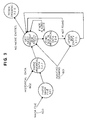
- Figure 1 is an example of a graphical display of a process and instrumentation diagram.
- Figure 2 is an example of a graphical display of a loop sheet with a graphical attribute interface, in accordance with the embodiment.
- Figures 3-5 are additional examples of graphical attribute interfaces, in accordance with the embodiment.
- Figure 6 is a system block diagram showing the functional requirements for implementing the graphical attribute interface which is used by the embodiment.
- Figure 7 is a flow chart showing the logic of the graphical attribute interface of the embodiment.
- Figure 8 is a flow chart showing in more detail the process user request function of Figure 7.
- Figure 9 is a flow chart showing in more detail the load drawing function of Figure 8.
- Figure 10 is a flow chart showing in more detail the unload drawing function of Figure 8.
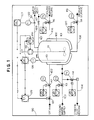
- FIG. 1 there is shown a screen from a computer display 90 which illustrates a loop sheet in the form of a process and instrumentation diagram (P&ID), for a batch kettle control.
- P&ID process and instrumentation diagram
- the bold lines indicate pipes or conduits for liquid, steam or vapor
- the fine lines indicate hardware connections
- the fine lines with circles indicate software connections.
- the screen display of Figure 1 shows kettle 100 surrounded by steam jacket 101, which is connected to steam line 102, cooling water supply line 103, condensate return line 104, and cooling water return 106.
- the input of unprocessed product is illustrated by use of charge header line 107, and processed product is removed for storage via outflow line 108. Also illustrated is vapor recovery line 109.
- stir bar 111 which is driven by motor 112. Also within kettle 100 is temperature sensor 113.
- lines 102, 103, 104, 106, 107 and 108 each respectively include valves 112, 113, 114, 116, 117 and 118.
- Each valve has associated therewith a valve state indicator (YV) and a valve indicator and controller (YIC).
- outflow line 108 includes outflow valve 118 which has associated therewith a valve state indicator (YV) 119, and a valve indicator and controller (YIC) 120.
- Vapor recovery line 109 includes a flow transducer 121 which is connected through flow transmitter (FT) 122 to flow rate indicator and controller (FIC) 123.
- FT flow transmitter
- FIC flow rate indicator and controller
- Temperature indicator 113 is connected through temperature transmitter (TT) 126 to temperature indicator and controller (TIC) 127. Also provided to TIC 127 is the control output of valve indicator and controller (YIC) 128, which is connected to monitor motor 112.
- TT temperature transmitter
- TIC temperature indicator and controller
- YIC valve indicator and controller
- valve state indicator associated with each component illustrated in the P&ID of Figure 1, for example, associated with each valve, valve state indicator (YV), indicator and controller (YIC), sensed signal transmitter (TT, FT), and flow or temperature indicator and controller (FIC, TIC), are so-called process attributes which completely define the identity and state of the particular component.
- process attributes associated with each graphical or icon representation of a control element in a P&ID such as that illustrated in Figure 1, are one or more process attributes.
- process attributes may include the name of the control element, the type, part number, and manufacturer of the control element, reference to the drawing for the control element, if the control element is a physical element, the type of signal output by the control element (for example, analog or digital), the engineering units for the signal or signals produced by the control element as well as the range for the output signal, the high and low alarm limits for the output signal, the value of the output signal at a particular point in time, the last time the control element was maintained, and so forth.
- process attributes reveal the identity, characteristics and/or state of a respective control element.
- the present invention allows selected process attributes to be formatted and displayed along with the graphical representation of the operation (for example, the P&ID sheet of the operation under consideration).
- the graphical representation of the operation for example, the P&ID sheet of the operation under consideration.
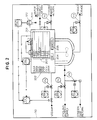
- an embodiment of the present invention contemplates the use of a cursor (such as cross-hairs 200) which is selectively placeable anywhere on the image of the P&ID sheet by use of a mouse, key board, joy stick, or other user input device, in order to select a particular control element of interest (for example, FT 122).
- a dialogue box 201 is displayed overlying the graphical representation of the P&ID sheet.
- Dialogue box 201 may take any form, however, in the preferred embodiment, dialogue box 201 includes at least two fields; a process attribute identity field 202 and a process attribute value field 203.
- Identity field 202 includes a brief description of the identity of the process attribute of interest, the value for which is displayed in the relevant entry of process attribute value field 203.
- Dialogue box 201 also includes graphical instruction boxes 204 and 205 with which the user may change or set attribute values by selecting an attribute value field 203 and entering a new value. Once changes have been made to values within field 203, selecting box 204 ("OK") saves the new values or selecting box 205 (“CANCEL”) retains the original values. In any case, selecting box 204 then box 205 closes the dialogue box 201.
- Figures 3,4 and 5 present examples of different types of dialogue boxes 201 which are illustrative of dialogue boxes that may be displayed for various control elements revealed in the P&ID sheet of Figure 1. It should be understood that for each dialogue box illustrated in Figures 3, 4 and 5, more or fewer process attribute identifiers may be included within the process attribute identification field, which would result in more or fewer process attribute values being displayed in the process attribute value fields.
- FIG 3 presented is an exemplary dialogue box 201A which may be overlaid on the P&ID sheet of Figure 1 (as illustrated in Figure 2), if the flow transmitter (FT) 122 was selected by the user for display of underlying attributes.
- FT flow transmitter
- process attribute identification field 202A includes a "tag" entry, with the corresponding value in field 203A being the tag that appears on the P&ID sheet for FT 122.
- Other attribute identifiers and values appearing in fields 202A and 203A indicate that FT 122 produces an output signal that is analog.
- the "device” and “address” entries in fields 202A and 203A indicate the hardware box actually housing the transmitter, and the address within that box.
- attribute identification and value fields 202A and 203A include entries for the engineering units of the output signal of FT 122 (ma), and the high and low values permitted for the output signal, in the specified engineering units.
- dialogue box 201B in Figure 4 presented is an exemplary dialogue box which may be displayed when the user selects product outflow valve 118 of the P&ID sheet of Figure 1 for display of underlying attributes.
- Process attribute identification and value fields 202B and 203B include entries that identify the name, type, part number and manufacturer of the valve in interest. In addition, the identification of the valve specification sheet is provided. Finally, fields 202B and 203B include entries for the last maintenance date for outflow valve 118.
- the dialogue boxes 201A and 201B shown in Figures 3 and 4 do not include process attributes that vary as the process proceeds. In other words, the process attributes are static rather than dynamic.
- the "Maintenance Date" entry in dialogue box 201B is periodically updated when the outflow 118 is maintained, but the other entries in dialogue box 201B do not vary as the process continues.
- control elements including control elements presented in icon form in the P&ID sheet of Figure 1, do include process attributes that vary with time (i.e., dynamic attributes).
- flow rate indicator and controller 123 produces an output signal which is indicative of the vapor flow rate detected by flow sensor 121 and transmitted by flow transmitter 122.
- Figure 5 presents an exemplary dialogue box 201C for flow rate indicator and controller 123. Similar to dialogue boxes 201A and 201B of Figures 3 and 4, dialogue box 201C for flow indicator and controller 123 reveals several process attributes that do not vary as the process proceeds. However, dialogue box 201C includes a process attribute identified as "Process Variable” with a corresponding value. This value (in units of gallons per minute) varies in proportion to the flow of vapor in line 109 as sensed by flow sensor 121 and as transmitted by flow transmitter 122, and will thus vary as the process under control proceeds. In a similar fashion, although the "Set Point”, “High Alarm”, and “Low Alarm” entries in dialogue box 201C are typically fixed throughout the duration of a control process, these values may either be changed by the operator or may be changed automatically under software control at any time.
- Process attribute identified as "Process Variable” with a corresponding value. This value (in units of gallons per minute) varies in proportion to the flow of vapor in line 109 as
- a data historian maintains values for these process attributes in a history data base in a known manner.
- the present invention operates to select and format particular process attributes for presentation in dialogue boxes which are overlaid upon the display of the loop sheet or P&ID sheet of interest. This provides a graphical display of process attributes for any point in time that is recorded in the history data base.
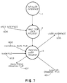
- FIG. 6 there is shown in functional block diagram form the graphical display of process attributes.
- the key parts of the embodiment are an AutoCAD drawing file 601, a data historian or historical data file 602, a mask file 603, and a processor 604 which processes user requests input through interface 606 to produce drawings including graphical representation of process attributes.
- These drawings are stored in AutoCAD drawing file 601, and are constructed from the AutoCAD drawing file 601, historical data file 602, and mask file 603, as described in more detail below.
- Drawing data file 607 is used to store a representation of the process attributes refined by mask file 603.
- Historical data file 602 contains attribute data which is to be loaded into the drawing.
- the data is organized by records, and each record contains a number of fields as defined by the mask file 603.
- the mask file 603 contains the definition of the structure records in the historical data file 602.
- the record definition is the list of attributes in each record in the historical data file. Attributes in the record which are proceeded by a special marking character (for example, a "@" character) are used as the key attributes for loading data from the historical data file 602.
- the preferred embodiment uses the interface provided in the AutoCAD Development System provided as part of AutoCAD release 11, and provides a mechanism for keeping process documentation up to date with the process itself. A user may to load and unload the process data directly into and out of process drawings.
- the preferred embodiment is designed to operate on the Fisher Controls ENVOX Open Database product, however, those of skill in this art will be able to apply the invention to other spread sheet and data base applications without undue experimentation.
- the embodiment uses the concept of "key attributes” which refers to the process attribute within a block of attributes whose value - the "key value” - designates the block for use in a drawing function, whether a load or an unload drawing function (described in detail with reference to Figures 9 and 10).
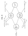
- FIG. 7-10 presented is a flow chart of the logic of the graphical attribute interface implemented in software.
- One of ordinary skill in the art may write source code from this flow chart in any suitable computer program language, such as Pascal, C, or FORTRAN for any desired computer system, such as IBM PC's or IBM compatible computers or other computers which support these computer languages.
- step 1 The process begins by initializing the users interface in step 1. This is done in accordance with the standard AutoCAD Development System interface procedures. Control then passes to step 2 where user input is awaited. Once user input is received, control passes to step 3 where the user request is processed. Step 3 uses as inputs, the historical data file 602, the mask file 603, the AutoCAD drawing file 601, and/or process attribute data from the drawing 607.
- Figure 8 shows in more detail the processing of the process user request (step 3) of Figure 7.
- step 3.1 the function code of the entered request is determined, and control passes either to the load drawing function 3.2 or the unload drawing function 3.3, which are described in more detail with reference to Figures 9 and 10.
- the mask file 603 is parsed.
- the mask file 603 is read and a structure is created from the mask file that defines the meaning of each item of data in historical data file 602.
- Control passes to block 3.2.2 where the historical data file 602 is parsed according to the information contained within mask file 603.
- the first dialogue box to be updated is determined from information in the mask file 603, historical data file 602 and AutoCAD drawing file 601. Control then passes to block 3.2.4 where the attribute data for the dialogue box under consideration is found in the historical data file. Control then passes to 3.2.5 where the dialogue box is updated. Control then loops back to block 3.2.3 for continued operation, until no additional dialogue box entities are discovered. Control then passes to block 3.2.6 where the AutoCAD drawing is regenerated and displayed.
- the mask file is parsed to establish the format of data to be output from AutoCAD drawing file 601 to the data from drawing file 607, and control passes to 3.3.2 where the data from drawing file 607 is opened.
- the AutoCAD drawing is reviewed in accordance with the parsed mask file data to identify each dialogue box. For each identified dialogue box, control then passes to block 3.3.4 where an output record is built from the dialogue box identified in block 3.3.3. Looping control continues in blocks 3.3.3 and 3.3.4 until no more dialogue boxes are found in AutoCAD drawing 601. Control then passes to block 3.3.5 where the output record is saved, in accordance with the parsed mask file 603, in the data from drawing file 607 established in block 3.3.2.
Claims (5)
- Méthode pour générer l'affichage graphique des attributs d'un procédé dans un contrôleur de procédé informatique comprenant des étapes consistant à:afficher une représentation graphique (P&ID) du procédé à contrôler;stocker dans un fichier de données historiques (602) l'historique des attributs du procédé concerné (203) pour une pluralité d'instants pendant le fonctionnement du procédé sous contrôle;stocker dans un fichier de données de masques (603) une information relative à l'historique des attributs sous-jacents (203) du procédé vers des éléments de procédé correspondants (112 - 118) dans la représentation graphique;choisir une partie de la représentation graphique (P&ID) et un instant où les attributs sous-jacents (203) du procédé doivent être affichés à partir de cet historique; etafficher les attributs sous-jacents (203) du procédé pour la partie choisie de la représentation graphique (P&ID) pour un instant choisi sensiblement en simultanéité avec l'affichage de la représentation graphique.
- Méthode selon la revendication 1, dans laquelle l'étape d'affichage des attributs de procédé (203) comprend l'étape consistant à superposer des indices (201) des attributs de procédé sur la représentation graphique.
- Méthode selon la revendication 1 ou 2, dans laquelle la représentation graphique comprend des icônes (119 - 129) pour les éléments (112 - 118) du procédé, l'étape consistant à choisir une partie de la représentation graphique comprenant les étapes consistant à choisir une icône d'un élément de procédé pour laquelle les attributs sous-jacents (202, 203) du procédé doivent être affichés.
- Méthode selon la revendication 3, dans laquelle les attributs sous-jacents du procédé comprennent l'identification (202B) d'un élément de procédé correspondant, les caractéristiques (203B) de l'élément de procédé correspndant et les états (203C) de l'élément de procédé correspondant.
- Système pour formater et afficher des données d'attributs d'un procédé avec les données graphiques du procédé, comprenant:un fichier de dessins (601) comprenant au moins une représentation graphique (P&ID) du procédé sous contrôle, une représentation graphique au moins comprenant une pluralité d'éléments de procédé (112 - 118);un fichier de données historiques (603) dans lequel sont stockées les données historiques relatives aux attributs (202, 203) du procédé sous-jacents chacun à la pluralité d'éléments du procédé (112 - 118) pour une pluralité d'instants;un fichier de données de masques (602) comprenant des informations qui se rapportent aux données historiques vers les éléments de procédé correspondants au moins (112 - 118) dans la représentation graphique; etun processeur de données (604), connecté fonctionnellement au fichier des dessins (601), au fichier des données historiques (602) et au fichier des masques (603), pour combiner au moins la représentation graphique (P&ID) avec les données historiques selon les informations dans le fichier des masques (603), afin de produire un affichage combiné de la représentation graphique au moins avec les attributs du procédé (202, 203) sous-jacents à au moins une pluralité d'éléments du procédé (112 - 118) pour un instant choisi.
Applications Claiming Priority (2)
| Application Number | Priority Date | Filing Date | Title |
|---|---|---|---|
| US07/958,046 US5896138A (en) | 1992-10-05 | 1992-10-05 | Process control with graphical attribute interface |
| US958046 | 1992-10-05 |
Publications (2)
| Publication Number | Publication Date |
|---|---|
| EP0592921A1 EP0592921A1 (fr) | 1994-04-20 |
| EP0592921B1 true EP0592921B1 (fr) | 1998-01-21 |
Family
ID=25500536
Family Applications (1)
| Application Number | Title | Priority Date | Filing Date |
|---|---|---|---|
| EP93116076A Revoked EP0592921B1 (fr) | 1992-10-05 | 1993-10-05 | ContrÔle du procédé avec interface graphique des propriétés |
Country Status (3)
| Country | Link |
|---|---|
| US (1) | US5896138A (fr) |
| EP (1) | EP0592921B1 (fr) |
| DE (1) | DE69316511T2 (fr) |
Cited By (9)
| Publication number | Priority date | Publication date | Assignee | Title |
|---|---|---|---|---|
| US7761923B2 (en) | 2004-03-01 | 2010-07-20 | Invensys Systems, Inc. | Process control methods and apparatus for intrusion detection, protection and network hardening |
| US7860857B2 (en) | 2006-03-30 | 2010-12-28 | Invensys Systems, Inc. | Digital data processing apparatus and methods for improving plant performance |
| US8023500B2 (en) | 1996-08-20 | 2011-09-20 | Invensys Systems, Inc. | Methods for process control with change updates |
| US8028272B2 (en) | 1999-05-17 | 2011-09-27 | Invensys Systems, Inc. | Control system configurator and methods with edit selection |
| US8090452B2 (en) | 1999-06-11 | 2012-01-03 | Invensys Systems, Inc. | Methods and apparatus for control using control devices that provide a virtual machine environment and that communicate via an IP network |
| US8368640B2 (en) | 1999-05-17 | 2013-02-05 | Invensys Systems, Inc. | Process control configuration system with connection validation and configuration |
| US8463964B2 (en) | 2009-05-29 | 2013-06-11 | Invensys Systems, Inc. | Methods and apparatus for control configuration with enhanced change-tracking |
| CN101681161B (zh) * | 2007-03-26 | 2013-09-18 | 霍尼韦尔国际公司 | 用于使过程控制系统中的控制技术可视化的装置和方法 |
| US8594814B2 (en) | 2008-06-20 | 2013-11-26 | Invensys Systems, Inc. | Systems and methods for immersive interaction with actual and/or simulated facilities for process, environmental and industrial control |
Families Citing this family (53)
| Publication number | Priority date | Publication date | Assignee | Title |
|---|---|---|---|---|
| US5918233A (en) * | 1996-05-30 | 1999-06-29 | The Foxboro Company | Methods and systems for providing electronic documentation to users of industrial process control systems |
| US5963886A (en) * | 1996-05-31 | 1999-10-05 | Eskom | Selective monitoring system |
| WO1997049018A1 (fr) * | 1996-06-19 | 1997-12-24 | Hoechst Celanese Corporation | Systeme et procede de commande de processus multitache |
| EP0906629B1 (fr) * | 1996-06-20 | 2003-02-19 | ABB Combustion Engineering Nuclear Power, Inc. | Dispositif de representation des conditions de fonctionnement critiques d'un systeme et methode idoine |
| US5892440A (en) * | 1997-05-14 | 1999-04-06 | Combustion Engineering Inc. | Alarm significance mapping |
| JPH1172499A (ja) * | 1997-08-29 | 1999-03-16 | Shimadzu Corp | 分析装置用システムコントローラ |
| EP0919896A1 (fr) * | 1997-12-01 | 1999-06-02 | Siemens Aktiengesellschaft | Méthode de définition et de paramétrage d'interfaces aidée par des fenêtres |
| US7234118B1 (en) * | 1997-12-15 | 2007-06-19 | International Business Machines Corporation | Method and apparatus for setting parameters in a system |
| US6067477A (en) * | 1998-01-15 | 2000-05-23 | Eutech Cybernetics Pte Ltd. | Method and apparatus for the creation of personalized supervisory and control data acquisition systems for the management and integration of real-time enterprise-wide applications and systems |
| US6690274B1 (en) | 1998-05-01 | 2004-02-10 | Invensys Systems, Inc. | Alarm analysis tools method and apparatus |
| EP0959398A1 (fr) * | 1998-05-01 | 1999-11-24 | The Foxboro Company | Procédé et appareil pour l'analyse des outils d'alarme |
| US6535122B1 (en) | 1998-05-01 | 2003-03-18 | Invensys Systems, Inc. | Method and apparatus for extending processing mask/filtering, and displaying alarm information for a hierarchically categorizing alarm monitoring system |
| US6219046B1 (en) | 1998-09-17 | 2001-04-17 | General Electric Company | Man-machine interface for a virtual annunciator panel display |
| US6670934B1 (en) | 1999-02-03 | 2003-12-30 | William H. Gates, III | Method and system for distributing art |
| US6466234B1 (en) * | 1999-02-03 | 2002-10-15 | Microsoft Corporation | Method and system for controlling environmental conditions |
| US6473638B2 (en) | 1999-12-24 | 2002-10-29 | Medtronic, Inc. | Medical device GUI for cardiac electrophysiology display and data communication |
| US6952807B1 (en) * | 2000-01-31 | 2005-10-04 | Daimlerchrysler Corporation | Vehicle supply chain analysis system |
| US6564226B1 (en) | 2000-09-18 | 2003-05-13 | Daimlerchyrsler Corporation | Supplier management process with dynamically updated mapping |
| US6825861B2 (en) * | 2001-01-08 | 2004-11-30 | Apple Computer, Inc. | Three state icons for operation |
| US20030065488A1 (en) * | 2001-09-25 | 2003-04-03 | Lockheed Martin Corporation | Distributed system and method for computer aided multi-component system design |
| US7496591B2 (en) | 2001-12-21 | 2009-02-24 | Honeywell International Inc. | Method and system for capturing, storing and retrieving events and activities |
| US7152068B2 (en) | 2001-12-21 | 2006-12-19 | Honeywell International Inc. | Method and apparatus for retrieving time series data related to an activity |
| US7027954B2 (en) | 2001-12-21 | 2006-04-11 | Honeywell International Inc. | Method and apparatus for retrieving activity data related to an activity |
| US7225193B2 (en) | 2001-12-21 | 2007-05-29 | Honeywell International Inc. | Method and apparatus for retrieving event data related to an activity |
| US20040061722A1 (en) * | 2002-09-27 | 2004-04-01 | Keith Christopher | Passdown database and flow chart |
| DE10213746B4 (de) * | 2002-03-26 | 2013-04-18 | Endress + Hauser Gmbh + Co. Kg | Vorrichtung zum Bedienen von Feldgeräten |
| US7469242B2 (en) * | 2002-05-23 | 2008-12-23 | The Boeing Company | Central based computer network of solid models and associated data with search capability |
| DE10243849A1 (de) * | 2002-09-20 | 2004-04-01 | Siemens Ag | Verfahren zur automatischen Anzeige zusätzlicher Daten |
| JP4185876B2 (ja) * | 2004-03-25 | 2008-11-26 | キヤノン株式会社 | 情報処理装置 |
| US20060173862A1 (en) * | 2004-12-29 | 2006-08-03 | Volker Sauermann | Method and system for displaying context-sensitive columns in a table |
| US7869900B2 (en) * | 2005-12-12 | 2011-01-11 | Balcones Fuel Technology, Inc. | Integrated cuber management system |
| JP4791840B2 (ja) * | 2006-02-06 | 2011-10-12 | 株式会社日立ハイテクノロジーズ | 荷電粒子線装置、走査電子顕微鏡、および試料検査方法 |
| US8001480B2 (en) | 2007-12-17 | 2011-08-16 | Honeywell International Inc. | Apparatus and method for defining and controlling graphical faceplates in a process control system |
| US10372833B2 (en) * | 2008-04-14 | 2019-08-06 | The Boeing Company | Part standard geometry management in a computer aided design system |
| KR20100034411A (ko) * | 2008-09-24 | 2010-04-01 | 삼성전자주식회사 | 파일 속성정보 입력 방법 및 장치 |
| US20100175029A1 (en) * | 2009-01-06 | 2010-07-08 | General Electric Company | Context switching zooming user interface |
| US8301419B1 (en) | 2009-10-09 | 2012-10-30 | The Boeing Company | Managing information for generating models of parts |
| US8589814B2 (en) | 2010-04-16 | 2013-11-19 | Honeywell International Inc. | System and method for visual presentation of information in a process control system |
| US9095002B2 (en) | 2010-07-12 | 2015-07-28 | Invensys Systems, Inc. | Methods and apparatus for process control with improved communication links |
| US8331855B2 (en) | 2010-07-12 | 2012-12-11 | Invensys Systems, Inc. | Methods and apparatus for process control with improved communication links |
| US8606378B2 (en) * | 2010-09-27 | 2013-12-10 | Fisher-Rosemount Systems, Inc. | Methods, apparatus, and articles of manufacture to identify hazardous process conditions associated with devices in a process control system |
| WO2012155972A1 (fr) * | 2011-05-19 | 2012-11-22 | Abb Research Ltd | Navigation par recouvrement dans une interface utilisateur |
| JP5846896B2 (ja) * | 2011-12-21 | 2016-01-20 | 株式会社日立製作所 | プラント監視制御装置 |
| US20150043302A1 (en) * | 2012-02-23 | 2015-02-12 | Meiji Co., Ltd. | Proportional mixing system |
| US9240164B2 (en) | 2013-02-27 | 2016-01-19 | Honeywell International Inc. | Apparatus and method for providing a pan and zoom display for a representation of a process system |
| US9977413B2 (en) | 2013-03-11 | 2018-05-22 | Honeywell International Inc. | Apparatus and method for managing open windows in a graphical display for a representation of a process system |
| MX2018003477A (es) | 2015-10-02 | 2018-06-20 | Halliburton Energy Services Inc | Configuraciones de valvula de ajuste en un sistema de colector. |
| US10318903B2 (en) | 2016-05-06 | 2019-06-11 | General Electric Company | Constrained cash computing system to optimally schedule aircraft repair capacity with closed loop dynamic physical state and asset utilization attainment control |
| USD876445S1 (en) * | 2016-10-26 | 2020-02-25 | Ab Initio Technology Llc | Computer screen with contour group organization of visual programming icons |
| USD844634S1 (en) | 2016-10-26 | 2019-04-02 | Ab Initio Technology Llc | Computer screen with visual programming icons |
| US20190114130A1 (en) * | 2017-10-18 | 2019-04-18 | Valmet Automation Oy | Industrial process control system |
| CN110275513A (zh) * | 2019-07-17 | 2019-09-24 | 四川朵唯物联技术有限公司 | 无线智能控制器测试方法、系统、及存储介质 |
| US20220155942A1 (en) * | 2020-11-18 | 2022-05-19 | Yokogawa Electric Corporation | Information processing apparatus, information processing method, and program |
Family Cites Families (26)
| Publication number | Priority date | Publication date | Assignee | Title |
|---|---|---|---|---|
| US4512747A (en) * | 1982-01-13 | 1985-04-23 | Hitchens Max W | Material conveying system simulation and monitoring apparatus |
| US4792888A (en) * | 1982-03-22 | 1988-12-20 | The Babcock & Wilcox Company | Exception processing of operator displays |
| CH661592A5 (de) * | 1983-06-10 | 1987-07-31 | Mettler Instrumente Ag | Verfahren zur optischen gewichtsdarstellung bei dosiervorgaengen sowie dosierwaage zur durchfuehrung des verfahrens. |
| US4967381A (en) * | 1985-04-30 | 1990-10-30 | Prometrix Corporation | Process control interface system for managing measurement data |
| US4873623A (en) * | 1985-04-30 | 1989-10-10 | Prometrix Corporation | Process control interface with simultaneously displayed three level dynamic menu |
| US4679137A (en) * | 1985-04-30 | 1987-07-07 | Prometrix Corporation | Process control interface system for designer and operator |
| US4805089A (en) * | 1985-04-30 | 1989-02-14 | Prometrix Corporation | Process control interface system for managing measurement data |
| US5032978A (en) * | 1986-05-05 | 1991-07-16 | Westinghouse Electric Co. | Status tree monitoring and display system |
| US4833622A (en) * | 1986-11-03 | 1989-05-23 | Combustion Engineering, Inc. | Intelligent chemistry management system |
| US4885694A (en) * | 1987-04-29 | 1989-12-05 | Honeywell Inc. | Automated building control design system |
| US4862376A (en) * | 1987-10-28 | 1989-08-29 | International Business Machines Corp. | Bill of material interface to CAD/CAM environment |
| US4862345A (en) * | 1987-11-16 | 1989-08-29 | Litwin Engineers & Constructors, Inc. | Process plant instrumentation design system |
| GB2224370B (en) * | 1988-11-01 | 1993-08-04 | Toshiba Machine Co Ltd | Input display apparatus |
| US5023817A (en) * | 1989-03-06 | 1991-06-11 | Xerox Corporation | Jam history and diagnostics |
| JP2907858B2 (ja) * | 1989-03-20 | 1999-06-21 | 株式会社日立製作所 | 表示装置および方法 |
| US5019961A (en) * | 1989-04-05 | 1991-05-28 | Cadware, Inc. | Computer apparatus and method for logical modelling |
| US5113350A (en) * | 1989-08-25 | 1992-05-12 | Beowulf Corporation | Computerized system for display and storage of materials batching information |
| JPH0650460B2 (ja) * | 1989-10-17 | 1994-06-29 | アプライド バイオシステムズ インコーポレイテッド | ロボットインターフェース |
| US5271045A (en) * | 1989-11-02 | 1993-12-14 | Combustion Engineering, Inc. | Advanced nuclear plant control complex |
| US5241482A (en) * | 1990-04-13 | 1993-08-31 | Honda Giken Kogyo Kabushiki Kaisha | Monitoring system for automated assemblies |
| US5239487A (en) * | 1990-10-24 | 1993-08-24 | International Business Machines Corporation | Computer integrated manufacturing rework apparatus and method |
| US5251152A (en) * | 1991-01-17 | 1993-10-05 | Hewlett-Packard Company | Storage and display of historical LAN traffic statistics |
| US5226118A (en) * | 1991-01-29 | 1993-07-06 | Prometrix Corporation | Data analysis system and method for industrial process control systems |
| US5253184A (en) * | 1991-06-19 | 1993-10-12 | Storage Technology Corporation | Failure and performance tracking system |
| US5321626A (en) * | 1991-09-25 | 1994-06-14 | Spd Technologies Inc. | Battery performance monitoring and forecasting system |
| US5253160A (en) * | 1991-12-02 | 1993-10-12 | Lin Cheng S | Centralized control means for manipulating plant control systems |
-
1992
- 1992-10-05 US US07/958,046 patent/US5896138A/en not_active Expired - Lifetime
-
1993
- 1993-10-05 DE DE69316511T patent/DE69316511T2/de not_active Revoked
- 1993-10-05 EP EP93116076A patent/EP0592921B1/fr not_active Revoked
Cited By (12)
| Publication number | Priority date | Publication date | Assignee | Title |
|---|---|---|---|---|
| US8023500B2 (en) | 1996-08-20 | 2011-09-20 | Invensys Systems, Inc. | Methods for process control with change updates |
| US8028272B2 (en) | 1999-05-17 | 2011-09-27 | Invensys Systems, Inc. | Control system configurator and methods with edit selection |
| US8028275B2 (en) | 1999-05-17 | 2011-09-27 | Invensys Systems, Inc. | Control systems and methods with smart blocks |
| US8225271B2 (en) | 1999-05-17 | 2012-07-17 | Invensys Systems, Inc. | Apparatus for control systems with objects that are associated with live data |
| US8229579B2 (en) | 1999-05-17 | 2012-07-24 | Invensys Systems, Inc. | Control systems and methods with versioning |
| US8368640B2 (en) | 1999-05-17 | 2013-02-05 | Invensys Systems, Inc. | Process control configuration system with connection validation and configuration |
| US8090452B2 (en) | 1999-06-11 | 2012-01-03 | Invensys Systems, Inc. | Methods and apparatus for control using control devices that provide a virtual machine environment and that communicate via an IP network |
| US7761923B2 (en) | 2004-03-01 | 2010-07-20 | Invensys Systems, Inc. | Process control methods and apparatus for intrusion detection, protection and network hardening |
| US7860857B2 (en) | 2006-03-30 | 2010-12-28 | Invensys Systems, Inc. | Digital data processing apparatus and methods for improving plant performance |
| CN101681161B (zh) * | 2007-03-26 | 2013-09-18 | 霍尼韦尔国际公司 | 用于使过程控制系统中的控制技术可视化的装置和方法 |
| US8594814B2 (en) | 2008-06-20 | 2013-11-26 | Invensys Systems, Inc. | Systems and methods for immersive interaction with actual and/or simulated facilities for process, environmental and industrial control |
| US8463964B2 (en) | 2009-05-29 | 2013-06-11 | Invensys Systems, Inc. | Methods and apparatus for control configuration with enhanced change-tracking |
Also Published As
| Publication number | Publication date |
|---|---|
| EP0592921A1 (fr) | 1994-04-20 |
| DE69316511T2 (de) | 1998-10-01 |
| US5896138A (en) | 1999-04-20 |
| DE69316511D1 (de) | 1998-02-26 |
Similar Documents
| Publication | Publication Date | Title |
|---|---|---|
| EP0592921B1 (fr) | ContrÔle du procédé avec interface graphique des propriétés | |
| US4718025A (en) | Computer management control system | |
| EP0711429B1 (fr) | Procede et systeme de generation d'un modele de commande uniforme s'appliquant a la programmation d'une commande de processus | |
| EP0141132B1 (fr) | Système de surveillance et d'alarme pour une application universelle | |
| US6701285B2 (en) | Method and apparatus for monitoring the operation of an industrial process | |
| US10139812B2 (en) | Dynamic user interface for configuring and managing a process control system | |
| US8170835B2 (en) | Data analysis applications | |
| US5818736A (en) | System and method for simulating signal flow through a logic block pattern of a real time process control system | |
| JP4906829B2 (ja) | フィールドデバイスコンフィギュレーションへのチェンジのレコードのトランザクションデーターベースを管理する為のシステム及び方法 | |
| JP5603316B2 (ja) | プロセスプラントの構成を容易にするためのユーザインタフェース方法、システム及び方法 | |
| JP4722887B2 (ja) | フィールドデバイスコンフィギュレーションへのチェンジのレコードのトランザクションデーターベースを管理する為のシステム及び方法 | |
| US5644487A (en) | Monitoring and control system and method | |
| US20090271726A1 (en) | Providing Convenient Entry Points for Users in the Management of Field Devices | |
| US4862345A (en) | Process plant instrumentation design system | |
| JP2000099112A (ja) | プロセス事象と傾向変動デ―タとの統合表示方法とシステム | |
| US7356773B1 (en) | Wizard builder, for application software, building a setup wizard which sets up a defacto interface between the application program and monitoring or control equipment | |
| WO2001029632A9 (fr) | Interface amelioree pour la gestion de definitions test | |
| JP2000339022A (ja) | 施設監視表示処理システム | |
| JP3240501B2 (ja) | プラントの運転状態表示方法及び装置 | |
| JP2835081B2 (ja) | プロセス表示装置 | |
| JPH02214926A (ja) | 画面表示装置 | |
| WO2006133020A1 (fr) | Affichage de donnees historiques associees a des dispositifs de champ utilises dans des installations de regulation de processus |
Legal Events
| Date | Code | Title | Description |
|---|---|---|---|
| PUAI | Public reference made under article 153(3) epc to a published international application that has entered the european phase |
Free format text: ORIGINAL CODE: 0009012 |
|
| AK | Designated contracting states |
Kind code of ref document: A1 Designated state(s): DE FR GB IT |
|
| RAP1 | Party data changed (applicant data changed or rights of an application transferred) |
Owner name: FISHER-ROSEMOUNT SYSTEMS, INC. |
|
| 17P | Request for examination filed |
Effective date: 19940823 |
|
| 17Q | First examination report despatched |
Effective date: 19951213 |
|
| GRAG | Despatch of communication of intention to grant |
Free format text: ORIGINAL CODE: EPIDOS AGRA |
|
| GRAG | Despatch of communication of intention to grant |
Free format text: ORIGINAL CODE: EPIDOS AGRA |
|
| GRAH | Despatch of communication of intention to grant a patent |
Free format text: ORIGINAL CODE: EPIDOS IGRA |
|
| GRAH | Despatch of communication of intention to grant a patent |
Free format text: ORIGINAL CODE: EPIDOS IGRA |
|
| GRAA | (expected) grant |
Free format text: ORIGINAL CODE: 0009210 |
|
| AK | Designated contracting states |
Kind code of ref document: B1 Designated state(s): DE FR GB IT |
|
| REF | Corresponds to: |
Ref document number: 69316511 Country of ref document: DE Date of ref document: 19980226 |
|
| ITF | It: translation for a ep patent filed |
Owner name: STUDIO TORTA S.R.L. |
|
| ET | Fr: translation filed | ||
| PLBI | Opposition filed |
Free format text: ORIGINAL CODE: 0009260 |
|
| PLBF | Reply of patent proprietor to notice(s) of opposition |
Free format text: ORIGINAL CODE: EPIDOS OBSO |
|
| 26 | Opposition filed |
Opponent name: SIEMENS AG Effective date: 19981020 |
|
| PLBF | Reply of patent proprietor to notice(s) of opposition |
Free format text: ORIGINAL CODE: EPIDOS OBSO |
|
| PLBF | Reply of patent proprietor to notice(s) of opposition |
Free format text: ORIGINAL CODE: EPIDOS OBSO |
|
| PGFP | Annual fee paid to national office [announced via postgrant information from national office to epo] |
Ref country code: FR Payment date: 19991011 Year of fee payment: 7 |
|
| PLBO | Opposition rejected |
Free format text: ORIGINAL CODE: EPIDOS REJO |
|
| APAC | Appeal dossier modified |
Free format text: ORIGINAL CODE: EPIDOS NOAPO |
|
| APAE | Appeal reference modified |
Free format text: ORIGINAL CODE: EPIDOS REFNO |
|
| APAC | Appeal dossier modified |
Free format text: ORIGINAL CODE: EPIDOS NOAPO |
|
| PG25 | Lapsed in a contracting state [announced via postgrant information from national office to epo] |
Ref country code: FR Free format text: LAPSE BECAUSE OF NON-PAYMENT OF DUE FEES Effective date: 20010629 |
|
| REG | Reference to a national code |
Ref country code: FR Ref legal event code: ST |
|
| PGFP | Annual fee paid to national office [announced via postgrant information from national office to epo] |
Ref country code: GB Payment date: 20011003 Year of fee payment: 9 |
|
| PGFP | Annual fee paid to national office [announced via postgrant information from national office to epo] |
Ref country code: DE Payment date: 20011022 Year of fee payment: 9 |
|
| REG | Reference to a national code |
Ref country code: GB Ref legal event code: IF02 |
|
| RDAH | Patent revoked |
Free format text: ORIGINAL CODE: EPIDOS REVO |
|
| RDAG | Patent revoked |
Free format text: ORIGINAL CODE: 0009271 |
|
| STAA | Information on the status of an ep patent application or granted ep patent |
Free format text: STATUS: PATENT REVOKED |
|
| 27W | Patent revoked |
Effective date: 20020315 |
|
| GBPR | Gb: patent revoked under art. 102 of the ep convention designating the uk as contracting state |
Free format text: 20020315 |
|
| APAH | Appeal reference modified |
Free format text: ORIGINAL CODE: EPIDOSCREFNO |