EP0592652B1 - Integriertes system zur aufnahme, projektion und anzeige von bildern und/oder virtuellen realität - Google Patents
Integriertes system zur aufnahme, projektion und anzeige von bildern und/oder virtuellen realität Download PDFInfo
- Publication number
- EP0592652B1 EP0592652B1 EP93911514A EP93911514A EP0592652B1 EP 0592652 B1 EP0592652 B1 EP 0592652B1 EP 93911514 A EP93911514 A EP 93911514A EP 93911514 A EP93911514 A EP 93911514A EP 0592652 B1 EP0592652 B1 EP 0592652B1
- Authority
- EP
- European Patent Office
- Prior art keywords
- image
- spectator
- images
- helmet
- eye
- Prior art date
- Legal status (The legal status is an assumption and is not a legal conclusion. Google has not performed a legal analysis and makes no representation as to the accuracy of the status listed.)
- Expired - Lifetime
Links
Images


Classifications
-
- G—PHYSICS
- G09—EDUCATION; CRYPTOGRAPHY; DISPLAY; ADVERTISING; SEALS
- G09B—EDUCATIONAL OR DEMONSTRATION APPLIANCES; APPLIANCES FOR TEACHING, OR COMMUNICATING WITH, THE BLIND, DEAF OR MUTE; MODELS; PLANETARIA; GLOBES; MAPS; DIAGRAMS
- G09B9/00—Simulators for teaching or training purposes
- G09B9/02—Simulators for teaching or training purposes for teaching control of vehicles or other craft
- G09B9/08—Simulators for teaching or training purposes for teaching control of vehicles or other craft for teaching control of aircraft, e.g. Link trainer
- G09B9/30—Simulation of view from aircraft
- G09B9/307—Simulation of view from aircraft by helmet-mounted projector or display
-
- H—ELECTRICITY
- H04—ELECTRIC COMMUNICATION TECHNIQUE
- H04N—PICTORIAL COMMUNICATION, e.g. TELEVISION
- H04N13/00—Stereoscopic video systems; Multi-view video systems; Details thereof
-
- H—ELECTRICITY
- H04—ELECTRIC COMMUNICATION TECHNIQUE
- H04N—PICTORIAL COMMUNICATION, e.g. TELEVISION
- H04N13/00—Stereoscopic video systems; Multi-view video systems; Details thereof
- H04N13/30—Image reproducers
- H04N13/363—Image reproducers using image projection screens
-
- H—ELECTRICITY
- H04—ELECTRIC COMMUNICATION TECHNIQUE
- H04N—PICTORIAL COMMUNICATION, e.g. TELEVISION
- H04N13/00—Stereoscopic video systems; Multi-view video systems; Details thereof
- H04N13/30—Image reproducers
- H04N13/332—Displays for viewing with the aid of special glasses or head-mounted displays [HMD]
- H04N13/344—Displays for viewing with the aid of special glasses or head-mounted displays [HMD] with head-mounted left-right displays
-
- H—ELECTRICITY
- H04—ELECTRIC COMMUNICATION TECHNIQUE
- H04N—PICTORIAL COMMUNICATION, e.g. TELEVISION
- H04N13/00—Stereoscopic video systems; Multi-view video systems; Details thereof
- H04N13/30—Image reproducers
- H04N13/356—Image reproducers having separate monoscopic and stereoscopic modes
-
- H—ELECTRICITY
- H04—ELECTRIC COMMUNICATION TECHNIQUE
- H04N—PICTORIAL COMMUNICATION, e.g. TELEVISION
- H04N13/00—Stereoscopic video systems; Multi-view video systems; Details thereof
- H04N2013/0074—Stereoscopic image analysis
- H04N2013/0088—Synthesising a monoscopic image signal from stereoscopic images, e.g. synthesising a panoramic or high resolution monoscopic image
Definitions
- the present application relates to an improved integral system for recording, projecting, viewing-hearing images and/or virtual reality.
- the spectator observes surroundings that the informatics system calculates in accordance with his relative position.
- the system responds by calculating only the surroundings that correspond to the visual and auditory field of the spectator in this situation.
- Latency is understood to mean the time that elapses from when the spectator moves until the informatics system calculates the image corresponding to the new situation.
- the refreshment rate is the number of images that the system can generate per second. The more realistic one wants the image to be, the more complex and numerous the calculations necessary to generate this, and thus the latency is greater and the refreshment rate is smaller. This means that the spectator undergoes a perceptive lag that considerably spoils the sensation of being immersed in the virtual world created.
- the images With “telepresence” the images, normally stereoscopic, are picked up from the real world, along with the sound.
- the system responds by taking in the surroundings that correspond to the new position. These surroundings can be observed and listened to by one or more spectators, but in this case all of them perceive the same.
- Invention patent ES-P9100194 covers a procedure for the projection of images with a monoscopic/stereoscopic effect using projectors of the conventional type. Its inventor is one of the inventors of this application. Also the North American company VPL (Visual Programming Language) has developed a virtual reality system based on images produced by computer methods and perceived by the individual by means of a helmet with a screen which the spectator has in front of him, heard by him through headphones, and felt through gloves. This technique is only used for computerized images. To our knowledge they have not developed the real image.
- VPL Visual Programming Language
- the viewing of this virtual reality does not in fact enable a totally real perception, since the processor does not allow viewing in real time as fast as the spectator may wish in relation to his capacity for searching for the image by turning his head, and the images are not real, but computer generated.
- the screens for each eye in this helmet are different and so there may be chromatic or synchronic differences. As each eye has a screen the precision of the image is less than if a larger screen for both eyes were built into the screen. IBM has also developed software for this purpose. Macintosh has also made a helmet for informatics virtual reality.
- EP-A-0 479 605 for a method and portable device for image production; this has one sole screen, and connections that transmit the image, with a lever for locating the image.
- GB-A-2187912 for a stereoscopic video system consisting of an alternative image obtaining system for enabling images to be viewed on a television
- JP-A-3048233 for a stereoscopic image recording and projection device which consists of a system for picking up and recording images and a projection device; the surroundings are recorded slowly, and this does not permanently pick up the 360 ° visual sphere.
- JP-A-62289083 covers a total field camera device, made up of three cameras, that record 360 ° horizontally and which is monitored on a television; this is not stereoscopic and images cannot be selected.
- US-A-4310849 for a stereoscopic video system made up of two screens that send images to each eye by optical fibre, by means of two different systems, UHF and VHF in each one of the eyes; the image is recorded with two cameras; several spectators can be connected to the same; the visual field cannot be selected.
- the object of this invention is to provide a system for recording, transmitting and reproudcing images/sound, such that the fiel of view corresponding to the image presented to a spectator can be selected from a larger field corresponding to the total solid angle covered by the recording means which pick up a scene , and which provides stereoscopic vision and stereophonic sound.
- the total solid angle is the cone of images that the lens picks up.
- the spectator does not in fact pick up the total area of this solid angle - instead, according to the support used a greater or smaller portion of the same is stored.
- the part of this scene that the lens is capagle of picking up is what we shall call total solid angle.
- a recording system capbable of picking up 360° vertically and 360° horizontally picks up a solid angle of 4 x 3.14 seteradians. In this case this would be the image recorded by the recording system in one sole frame or shot equivalent to a visual sphere, and at a rate of 25 frames per second.
- the sound recording system uses several dierectional microphones spread out to take in the angle of the image, for example, 8 microphones laid out in a star shape for a 360° image.
- the sound recorded by each microphone is independently recorded on a different sound track, so that in this case 8 tracks would simultaneously be recorded. These can be increased or reduced according to the angle and type of microphones, and thus convey to the spectator the particular sound that pertains to the angle of the image that the spectator is perceiving.
- the surroundings are thus made up of the total solid angle and the audio channels.
- the transmission of data can be via cable or cordless system, the latter being preferable as it provides each spectator's independence.
- the transmission system will be called the emission system.
- the helmet is the support that enables the spectator to get into the real scene which is picked up by the surroundings recording systems.
- This system furthermore allows one to superimpose surroundings generated by computer on these surroundings from the real world.
- the viewing/audio system consists of:
- the reception system receives the signal picked up by the recording system and transmitted by the emission system.
- the emission system receives the signal picked up by the recording system and transmitted by the emission system.
- a cordless signal with the reception system transforming the same into a numerical system that can be processed.
- the date processor receives the signal that corresponds to the total solid angle that is picked up by the recording system, and allows the spectator to have access only to the information of the surroundings of interest to him, which corresponds to the visual solid angle of the spectator, who selects this by the position of his head or his eyes, and which calculates what portion of the image and sound the spectator would pick up in each eye from his own viewpoint, filters it to this end, and only sends on to the viewing system those pixels that make up the visual solid angle and ignores the rest of the information contained in the frame. It also includes a level detector in order to correct the inclination of the spectator's head.
- Each change of position of the head or the eyes is sent to the processor, that recalculates in real time the portion of the image and sound that the spectator would pick up from his new viewpoint and carries out further filtering so that the spectator receives the image corresponding to his new relative position. It also sends the data processor the values of distance between the eyes and those of eye convergence.
- the first of these values means that servomechanisms can adjust the optical system to the distance between the eyes of each individual. The spectator thus manages to combine in one sole image the two that reach both his eyes.
- Eye convergence is used to calculate the portions of ,the image that the data processor sends to the viewing system from the two frames that make up a stereoscopic pair. This is done so that the spectator does not undergo visual fatigue by trying to focus on objects that lie at distances different to those of the lenses that pick up the real scene.
- the scene to which the spectator has access only depends on the total solid angle that the recording system can record. If for example, we consider a recording system that records a solid angle of 180 ° vertically and 360 ° horizontally, the possible visual solid angles to which the spectator has access are spread over a semi-sphere that would have the horizon as a base.
- the extreme case is a recording system that picks up a total solid angle of 360 ° vertically and 360 ° horizontally.
- the filtering of the image is done by digitalizing and dividing into a fixed number of "pixels" that depend on the definition of the recording system used and on the screens of the viewing system.
- each one of the pixels that make up the frame is assigned a numerical code, that indicates its relative position in respect of certain coordinate axes.
- the frame is a numerical sequence that takes in the totality of the pixels and thus the total number of numerical codes, that is, the relative coordinates.
- the recording system picks up 25 or 50 frames per second and the emission system transmits 25 or 50 frames per second, understanding "frame” to mean each visual reading unit made up of the totality of the pixels and the numerical codes that make up the total solid angle.
- the processor sends the same image to each eye, but with stereoscopic vision it sends each eye the image corresponding to its own viewpoint.
- the viewing system consists of the following items:
- the image that each of the spectator's eyes receives is normally formed on two liquid crystal screens.
- the right eye is thus assigned one screen and the left eye another.
- the image reaches the ball of the eye by means of an optical-system that enables this to be seen in spite of the fact that the screens are placed at a distance closer than that at which the eye can focus.
- the difference between this helmet and those already known of lies in the fact that only one screen is needed.
- the spectator can perceive a monoscopic or stereoscopic image thanks to the existence and the operation of light shutters placed between the eyes and the screen that generates the image and also due to a higher frequency in the generation of images.
- the optical system is a set of items that enable both eyes to see the screen, in such a way that the light beam coming from the screen is split into two beams that are projected before the spectators eyes.
- the screen alternatively generates the image that corresponds to each eye.
- the generation system is for example: LI-RI-LI-RI or alternatively RI-LI-RI-LI ... without it mattering which of these is used.
- the cycle is again repeated and this happens 25 times a second, which means that the screen generates 100 ips, 50 of these for the right eye's viewpoint and 50 for the left eye's viewpoint.
- the shutter corresponding to each eye will be open or closed, in such a way that the image only reaches the eye that it should reach.
- LS being the left shutter and RS the right one.
- the helmet can be fitted with a switch that synchronizes both eyes to either of the images that form the stereoscopic pair. In this way people sensitive to this can obtain monoscopic vision even though at that time the emission system is sending out a stereoscopic signal.
- the image formed always by one sole screen means that the size of the same can be greater than on conventional helmets and thus provided with greater definition than on these, and the image for both eyes is identical as regards luminosity and chromatism, and can be located in any position.
- the screen should have a proper size to enable the formation of the circular image that corresponds to a visual solid angle.
- the helmet also includes the mechanisms required for this to adapt perfectly to the particular physiological characteristics of each spectator, the distance between pupils, and specific optical correction for each eye, both manual and automatic.
- the helmet adapts to any of the visual solid angles that are covered in the total solid angle.
- the system can be configured in different options:
- This option is used for a fixed number of spectators.
- the screen instead of being portable, is found in a centralized system along with the rest of the screens for the other spectators.
- This is a central unit made up of as many screens, data processors, light shutters and emission / receptions systems as the number of spectators desired.
- the central unit sends the personalized image and sound to each of the spectators helmets and receives from these the data regarding head and eye position. This is the ideal format for particular aspects such as interactive play of images and/or virtual reality.
- Figure 1 shows a diagrammatic view of the solid angle that the camera picks up, as well as its format.
- Figure 2 shows a view of the total solid angle.
- Figure 3 shows a diagrammatic figure that represents an example of the vision in a frame of 360 ° and vertical angle of 45 ° .
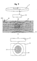
- Figure 4 shows a diagram of the development of the cylinder of 360 ° of figure 3.
- Figure 5 shows a diagram of how the sound is picked up for the 360 ° frame.
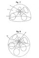
- Figure 6 shows a diagram of the view possible for a spectator according to the position his head is in.
- Figure 7 shows a diagram of the view possible for a spectator in accordance with a recording at an angle of 180 ° vertically and 360 ° on a horizontal plane.
- Figure 8 shows a diagram of the view possible for a spectator in accordance with a recording at a vertical angle of 360 ° and one of 360 ° on a horizontal plane.
- Figure 9 shows a diagram of the digitalization of the screen 360 ° horizontally and 100 ° vertically, and its relation to the content observed by the spectator.
- Figure 10 shows a diagram of the areas of a frame developed in which the spectator can vary his initial position.
- Figure 11 shows a diagram of the system of perception of the images by each eye using a small sized screen fitted into the helmet.
- Figure 11a shows a diagram of the system of perception of the images by each eye using a large sized screen fitted outside the helmet.
- Figure 12 shows a system of shutting out the image in accordance with the projection for the right hand frames.
- Figure 13 is a diagram of the positioning system.
- Figure 1 which shows a diagrammatic view of the solid angle taken by the camera
- 1 is the format of the camera and is appreciated as an example of the solid angle, indicated 45 ° , taken by the lens.
- Figure 3 that shows a diagrammatic figure that represents an example of the view of a frame of 360 ° and vertical angle of 45 °
- 4 indicates the spectator, who can choose between images 5a and 5c set at opposite points and not simultaneously visible by the same spectator of the screen whose images he chooses, indicated as 6.
- Figure 4 that shows a diagram of the development of the 360 ° cylinder in Figure 3, one can appreciate the way spectator 4 is able to observe any of the infinite points of view, for example 5a, 5b and 5c, within the visible spectrum that can be observed by modifying the position of his head or eyes.
- FIG 5 there is a diagram of the sound take for the 360 ° frame in which we can see the directional microphones, for example eight of these - 7 a, b, c, d, e, f and g - with which the sound is obtained, whose recording 8 can be selected at the time of the reproduction, in accordance with the image reproduced and the position of the spectator in respect of said image.
- the directional microphones for example eight of these - 7 a, b, c, d, e, f and g - with which the sound is obtained, whose recording 8 can be selected at the time of the reproduction, in accordance with the image reproduced and the position of the spectator in respect of said image.
- Figure 6 there is a diagram of a spectator's possible view, according to the position assumed by his head, in a frame in which spectator 4 receives the image in accordance with the position of his head.
- Figure 7 shows a diagram of a spectator's possible view according to a recording of an angle of 180 ° on a vertical plane and 360 ° horizontally, by means of which said spectator can pick up an image of the upper semi-sphere surrounding him 9, choosing any of the points of view 5 on which his vision can concentrate.
- Figure 8 shows a diagram of a spectator's possible view according to a recording of an angle of 360 ° on a vertical plane and 360 ° horizontally, by means of which said spectator can pick up an image of the upper semi-sphere surrounding him 10.
- Figure 9 shows a diagram of the digitalization of the screen 360 ° horizontally and for example 45 ° vertically, and its relationship to what is observed by the spectator, in which screen 6 is digitalized 11, being analyzed and broken down into pixels 12, with the spectrum visible by both eyes indicated as 13, the spectrum visible by either one of the eyes 14, which is processed 15. As a result of this processing, the spectator only perceives for his point of view the image 13 on screen 16 according to his possible spectrum of vision 14.
- Figure 10 there is a diagram of the area of a frame made in which the spectator can vary his relative position, bearing in mind that the points of view that are represented diagrammatically such as 5 as appearing at one end are actually complemented by the next part of the frame, since this is circular.
- Figure 11 there is a diagram of the system of perception of the images of each eye using a screen of a relatively small size, indicated 16, and fitted as an integral part of the helmet, in which there is an optical system 19 and light shutters, 17 for the left eye and 18 for the right eye.
- Figure 11a shows a diagram of the system of perception of images by each eye using a screen 16 of large size set outside the helmet, which through an image transmission system 19 and one for selecting each eye 20, becomes visible in the small screens 21 and 22 that each spectator has in his helmet, through the light shutters 17 and 18.
- Figure 12 shows a system of shutting out the images in accordance with the projection for the left hand frames, in which 5i indicates the projection of the image for the left eye, in correspondence with the left hand shutter 22 that is open, enabling the viewing of the content of the image projected, whilst the right shutter 21 is closed.
- Figure 12a shows a system of shutting out the images in accordance with the projection for the right hand frames, in which 5d indicates the projection of the image for the right eye, in correspondence with the right hand shutter 21 that is open, enabling the viewing of the content of the image projected, whilst the left shutter 22 is closed.
- Figure 13 shows a diagram of the positioning system, in which 23 indicates the data processor that receives the information from the positioning system 24, from the reception system 25, and determines the sound that has to reach the headphones 26 and the image that has to be shown on each screen, with 5i corresponding to the left eye and 5d to the right eye.
- the industrial application of this invention takes in from the recording of films to the projection of these in commercial cinemas in accordance with this new concept that is expressed by the content of this application.
Landscapes
- Engineering & Computer Science (AREA)
- Multimedia (AREA)
- Signal Processing (AREA)
- Theoretical Computer Science (AREA)
- Educational Technology (AREA)
- Business, Economics & Management (AREA)
- Physics & Mathematics (AREA)
- Educational Administration (AREA)
- Aviation & Aerospace Engineering (AREA)
- General Physics & Mathematics (AREA)
- Testing, Inspecting, Measuring Of Stereoscopic Televisions And Televisions (AREA)
- Stereophonic System (AREA)
- Television Signal Processing For Recording (AREA)
- Electroluminescent Light Sources (AREA)
- Diaphragms For Electromechanical Transducers (AREA)
- Paper (AREA)
- Holo Graphy (AREA)
- Non-Silver Salt Photosensitive Materials And Non-Silver Salt Photography (AREA)
- Devices For Indicating Variable Information By Combining Individual Elements (AREA)
Claims (11)
- Ein Integral-System zum Aufzeichnen, Senden, Projizieren, Sehen und Hören von realen Bildern oder Kombinationen solcher mit Virtual-Reality-Bildern, wobei ein Bild von einem Blickpunkt für jedes Auge eines Betrachters projiziert wird, in einem Helm, der mit den Vorrichtungen für die Bildbetrachtung und mit Kopfhörern ausgestattet ist. Das System besteht aus:einer Vielzahl von Empfangsvorrichtungen, einer pro Betrachter, Bildaufzeichnungsvorrichtungen, ausgerüstet mit mindestens einer Kamera zur Aufzeichnung von Bildsequenzen, wobei jede Sequenz einen gesamten, von der genannten mindestens 1 Kamera aufgenommenen Raumwinkel darstellt, der zumindest 100 Grad und bis zu 360 Grad horizontal und vertikal umfasst, und mit einer Mindestgeschwindigkeit von 25 Bildern pro Sekunde arbeitet, wobei jedes Bild digitalisiert und jedem digitalisierten Pixel des Bildes, dargestellt durch eine sich aus der Digitalisierung ergebende Sequenz, ein Code zugeordnet wird, der die erforderliche Position in dem Sehkreis des Betrachters hinsichtlich der Bezugskoordinaten angibt,Speicher zum Speichern der digitalisierten Pixelwerte und zugeordneten Codes,Übertragungsmittel zum Übertragen des Speicherinhalts oder des Speicherinhalts und zugeordneter Umfeldinformation, die die genannten Virtual-Reality-Bilder darstellt, und Mittel für die Tonübermittlung in Audiokanälen zu jeder Empfangsstation,wobei die einem Betrachter zugeordnete Empfangsstation folgendes umfasst:einen Empfänger (25) zum Empfang der übertragenen Bild- und Toninformation,einen Helm, der an ein Video/Audio-System angeschlossen ist, welches aus einem Positioner (24) besteht, der die relative Stellung in dem genannten Sehkreis des Betrachters bestimmt mit Bezug auf den gesamten, von den Kameras bedienten Raumwinkel, und zwar in einer von allen anderen Betrachtern unabhängigen Weise;einen Prozessor (23) zur Filterung der empfangenen Bildinformation und zum Mischen der empfangenen Audiokanalsignale entsprechend der durch den erwähnten Positioner vorgegebenen Koordinaten und zwar derart, dass der Betrachter nur die seiner Position entsprechenden Bild- und Tonfelder empfängt,ein Videosystem (16-22) mit einem Einzelmonitor (16) zur Bilderzeugung, mit Bildübertragunsmitteln (19, 20), einem Verschluss (21, 22), der die erzeugten Bilder entsprechend jedem Auge filtert undein Audiosystem (26) zur Reproduktion des der genannten Position entsprechenden Tons.
- Ein System nach Anspruch 1, dadurch gekennzeichnet, dass eine Mehrzahl von Mikrophonen (7) den Ton im gesamten 360° Bereich aufnimmt, deren Spuren in der Projektion derart gemacht werden, dass, in Übereinstimmung mit dem Blickpunkt des Betrachters, die Tonübermittlung derart erfolgt, dass sie mit dem Bild übereinstimmt unter frontaler Ausrichtung der Töne, die von dem durch den Betrachter betrachteten Bild kommen.
- Ein System nach Anspruch 1 und 2, dadurch gekennzeichnet, dass der Helm für das Projizieren und Betrachten der Bilder und die Klangwiedergabe folgendes beinhaltet:einen Kopf-Positioner, der die Position des Helms in Bezug auf das zu projizierende Bild bestimmt,einen Augen-Positioner, der, in Übereinstimmung mit der Position der Augen, die Wahl der Bilder vornimmt, die in dem von den Augen nach dem Bild abgesuchten Bereich sichtbar sind.einen Augen-Konvergenz-Detektor, der die Kurz- und Langstrecken-Scharfeinstellung bestimmt,ein Horizontal-Ausrichtgerät, das dafür sorgt, dass die Projizierung der Bilder, unabhängig von der seitlichen Kopfneigung des Betrachters, immer vertikal erfolgt,einen Wahlschalter zum Einstellen und Hören von Mono- oder Stereoklang, unabhängig vom einem weiteren Wahlschalter für Mono-/Stereoskopik-Bild-Einstellung,Lichtverschlüsse (17, 18), mit der die Wahl der auf den genannten Einzelmonitor des Helms übermittelten Bilder für jeden der Gesichtspunkte eines jeden Auges bestimmt wird, bzw. mit Hilfe eines Empfangssystems für die auf den genannten Einzelmonitor projizierten und durch optische Glasfaser an jeden Betrachter übertragenen Bilder;der Bereich des projizierten Bildes (14) ist rund and etwas grösser als der der menschlichen Sicht;das optische System bzw. das der Bildübertragung basiert auf Refraktion oder Reflektion bzw. die Bildübertragung erfolgt durch optische Glasfaser.
- Ein System nach Anspruch 1 und 2, dadurch gekennzeichnet, dass der Helm mit optischen Korrektur- und Einstellsystemen zur Anpassung an die Sichtentfernung des Betrachters ausgestattet ist.
- Ein System nach Anspruch 1, dadurch gekennzeichnet, dass das digitalisierte Bild für eine mögliche Mischung mit anderen, durch den Computer erzeugten Bildern gefiltert wird.
- Ein System nach Anspruch 1 und 3, dadurch gekennzeichnet, dass die sichtbaren Bilder (13) in Übereinstimmung mit jedem der möglichen Gesichtspnkte des Betrachters und der Neigung und Ausrichtung des Helms gemacht und/oder erzeugt werden.
- Ein System nach Anspruch 1 und 3, dadurch gekennzeichnet, dass jedes Bilderpaar in jeder Sekunde auf dem Monitor (16) in der folgenden Sequenz wiedergegeben wird, wobei LI die Wiedergabe des mit dem linken Auge gesehenen Teiles und RI des mit dem rechten Auge gesehenen Teiles ist.
PAARE (ungerade) 1 bis 25 LI-RI-LI-RI PAARE (gerade) 2 bis 24 LI-RI-LI-RI PAARE (ungerade) 1 bis 25 LI-RI-LI-RI LS-RS-LS-RS PAARE (gerade) 2 bis 24 LI-RI-LI-RI LS-RS-LS-RS - Ein System nach Anspruch 3, dadurch gekennzeichnet, dass in einer möglichen Ausformung des Helms das Empfangssystem, der Daten-Prozessor, der Monitor, das optische System, die Lichtverschlüsse, das Audiosystem und das System für die Kopf- und Augenausrichtung untergebracht sind.
- Ein System nach Anspurch 3, dadurch gekennzeichnet, dass in einer möglichen Ausformung des Helms ein Teil des optischen Systems, das Audiosystem und das Kopfausrichtsystem untergebracht sind, und dass sich an der Aussenseite des Helms der Monitor, das Empfangssystem, der Daten-Prozessor, die Lichtverschlüsse befinden, und dass diese gesamte Ausrüstung an den Helm angeschlossen ist.
- Ein System nach Anspruch 3, dadurch gekennzeichnet, dass in einer möglichen Ausformung des Helms ein Teil des optischen Systems, das Audiosystem und das Kopfausrichtsystem untergebracht sind, und dass auf der Aussenseite des Helmes die Zentraleinheit angebracht ist, die aus so vielen Monitoren, Datenprozessoren, Lichtverschlüssen und Sende-und Empfangssystemen besteht wie es mögliche Betrachter gibt.
- Ein System nach irgendeinem der Ansprüche 1, 2, 3 und 6, dadurch gekennzeichnet, dass die gewählten und empfangenen Bilder und Ton in Realzeit realisiert werden.
Applications Claiming Priority (3)
| Application Number | Priority Date | Filing Date | Title |
|---|---|---|---|
| ES09200907A ES2043549B1 (es) | 1992-04-30 | 1992-04-30 | Sistema integral de grabacion, proyeccion-visualizacion-audicion de imagenes y/o realidad virtual perfeccionado. |
| ES9200907 | 1992-04-30 | ||
| PCT/ES1993/000034 WO1993022879A2 (es) | 1992-04-30 | 1993-04-27 | Sistema integral de grabacion, proyeccion-visualizacion-audicion de imagenes y/o realidad virtual perfeccionado |
Publications (2)
| Publication Number | Publication Date |
|---|---|
| EP0592652A1 EP0592652A1 (de) | 1994-04-20 |
| EP0592652B1 true EP0592652B1 (de) | 1997-09-17 |
Family
ID=8276879
Family Applications (1)
| Application Number | Title | Priority Date | Filing Date |
|---|---|---|---|
| EP93911514A Expired - Lifetime EP0592652B1 (de) | 1992-04-30 | 1993-04-27 | Integriertes system zur aufnahme, projektion und anzeige von bildern und/oder virtuellen realität |
Country Status (11)
| Country | Link |
|---|---|
| EP (1) | EP0592652B1 (de) |
| JP (1) | JPH07500231A (de) |
| KR (1) | KR940701629A (de) |
| AT (1) | ATE158460T1 (de) |
| CA (1) | CA2112470A1 (de) |
| DE (1) | DE69313967D1 (de) |
| ES (1) | ES2043549B1 (de) |
| FI (1) | FI935949A (de) |
| NO (1) | NO934815L (de) |
| TW (1) | TW224163B (de) |
| WO (1) | WO1993022879A2 (de) |
Cited By (4)
| Publication number | Priority date | Publication date | Assignee | Title |
|---|---|---|---|---|
| US11016579B2 (en) | 2006-12-28 | 2021-05-25 | D3D Technologies, Inc. | Method and apparatus for 3D viewing of images on a head display unit |
| US11228753B1 (en) | 2006-12-28 | 2022-01-18 | Robert Edwin Douglas | Method and apparatus for performing stereoscopic zooming on a head display unit |
| US11275242B1 (en) | 2006-12-28 | 2022-03-15 | Tipping Point Medical Images, Llc | Method and apparatus for performing stereoscopic rotation of a volume on a head display unit |
| US11315307B1 (en) | 2006-12-28 | 2022-04-26 | Tipping Point Medical Images, Llc | Method and apparatus for performing rotating viewpoints using a head display unit |
Families Citing this family (8)
| Publication number | Priority date | Publication date | Assignee | Title |
|---|---|---|---|---|
| US6064355A (en) * | 1994-05-24 | 2000-05-16 | Texas Instruments Incorporated | Method and apparatus for playback with a virtual reality system |
| CA2264887A1 (en) * | 1996-09-09 | 1998-03-19 | Imax Corporation | Method and apparatus for presenting a visual display to an audience |
| US6317127B1 (en) | 1996-10-16 | 2001-11-13 | Hughes Electronics Corporation | Multi-user real-time augmented reality system and method |
| US20010056574A1 (en) * | 2000-06-26 | 2001-12-27 | Richards Angus Duncan | VTV system |
| DE10305820B4 (de) * | 2003-02-12 | 2006-06-01 | Fraunhofer-Gesellschaft zur Förderung der angewandten Forschung e.V. | Vorrichtung und Verfahren zum Bestimmen einer Wiedergabeposition |
| US7606372B2 (en) | 2003-02-12 | 2009-10-20 | Fraunhofer-Gesellschaft Zur Foerderung Der Angewandten Forschung E.V. | Device and method for determining a reproduction position |
| CN101819741B (zh) * | 2009-02-27 | 2013-05-29 | 上海复旦上科多媒体有限公司 | 沉浸式360°环型多媒体演示装置 |
| TWI636455B (zh) * | 2017-05-02 | 2018-09-21 | 國立臺灣師範大學 | Wearable recording device |
Family Cites Families (7)
| Publication number | Priority date | Publication date | Assignee | Title |
|---|---|---|---|---|
| US4310849A (en) * | 1979-06-11 | 1982-01-12 | Glass Stuart M | Stereoscopic video system |
| JPS62210797A (ja) * | 1986-03-12 | 1987-09-16 | Sony Corp | 立体画像観視装置 |
| JPS62289083A (ja) * | 1986-06-09 | 1987-12-15 | Nikon Corp | 広視野ビデオカメラ装置 |
| GB8701288D0 (en) * | 1987-01-21 | 1987-02-25 | Waldern J D | Perception of computer-generated imagery |
| JPH0348233A (ja) * | 1989-07-17 | 1991-03-01 | Sony Corp | 立体映像記録及び投影装置 |
| EP0479605B1 (de) * | 1990-10-05 | 1995-09-20 | Texas Instruments Incorporated | Verfahren und Gerät zur Erzeugung einer tragbaren optischen Anzeige |
| ES2034915A6 (es) * | 1990-10-25 | 1993-04-01 | Coll Maneu Juan | Sistema tridimensional de vision. |
-
1992
- 1992-04-30 ES ES09200907A patent/ES2043549B1/es not_active Expired - Fee Related
- 1992-06-29 TW TW081105101A patent/TW224163B/zh active
-
1993
- 1993-04-27 WO PCT/ES1993/000034 patent/WO1993022879A2/es active IP Right Grant
- 1993-04-27 EP EP93911514A patent/EP0592652B1/de not_active Expired - Lifetime
- 1993-04-27 JP JP5518948A patent/JPH07500231A/ja active Pending
- 1993-04-27 CA CA002112470A patent/CA2112470A1/en not_active Abandoned
- 1993-04-27 KR KR1019930704126A patent/KR940701629A/ko not_active Application Discontinuation
- 1993-04-27 AT AT93911514T patent/ATE158460T1/de not_active IP Right Cessation
- 1993-04-27 DE DE69313967T patent/DE69313967D1/de not_active Expired - Lifetime
- 1993-12-27 NO NO934815A patent/NO934815L/no unknown
- 1993-12-30 FI FI935949A patent/FI935949A/fi not_active Application Discontinuation
Cited By (6)
| Publication number | Priority date | Publication date | Assignee | Title |
|---|---|---|---|---|
| US11016579B2 (en) | 2006-12-28 | 2021-05-25 | D3D Technologies, Inc. | Method and apparatus for 3D viewing of images on a head display unit |
| US11036311B2 (en) | 2006-12-28 | 2021-06-15 | D3D Technologies, Inc. | Method and apparatus for 3D viewing of images on a head display unit |
| US11228753B1 (en) | 2006-12-28 | 2022-01-18 | Robert Edwin Douglas | Method and apparatus for performing stereoscopic zooming on a head display unit |
| US11275242B1 (en) | 2006-12-28 | 2022-03-15 | Tipping Point Medical Images, Llc | Method and apparatus for performing stereoscopic rotation of a volume on a head display unit |
| US11315307B1 (en) | 2006-12-28 | 2022-04-26 | Tipping Point Medical Images, Llc | Method and apparatus for performing rotating viewpoints using a head display unit |
| US11520415B2 (en) | 2006-12-28 | 2022-12-06 | D3D Technologies, Inc. | Interactive 3D cursor for use in medical imaging |
Also Published As
| Publication number | Publication date |
|---|---|
| WO1993022879A3 (es) | 1993-12-23 |
| ATE158460T1 (de) | 1997-10-15 |
| ES2043549A2 (es) | 1993-12-16 |
| TW224163B (de) | 1994-05-21 |
| EP0592652A1 (de) | 1994-04-20 |
| WO1993022879A2 (es) | 1993-11-11 |
| FI935949A0 (fi) | 1993-12-30 |
| DE69313967D1 (de) | 1997-10-23 |
| KR940701629A (ko) | 1994-05-28 |
| NO934815D0 (no) | 1993-12-27 |
| ES2043549B1 (es) | 1996-10-01 |
| JPH07500231A (ja) | 1995-01-05 |
| ES2043549R (de) | 1996-02-16 |
| NO934815L (no) | 1994-02-04 |
| FI935949A (fi) | 1994-02-28 |
| CA2112470A1 (en) | 1993-11-11 |
Similar Documents
| Publication | Publication Date | Title |
|---|---|---|
| US6246382B1 (en) | Apparatus for presenting stereoscopic images | |
| US7429997B2 (en) | System and method for spherical stereoscopic photographing | |
| KR100812905B1 (ko) | 입체 화상 처리 방법, 장치 및 컴퓨터 판독가능 기록 매체 | |
| US4647965A (en) | Picture processing system for three dimensional movies and video systems | |
| US4723159A (en) | Three dimensional television and video systems | |
| US20160344999A1 (en) | SYSTEMS AND METHODs FOR PRODUCING PANORAMIC AND STEREOSCOPIC VIDEOS | |
| EP0592652B1 (de) | Integriertes system zur aufnahme, projektion und anzeige von bildern und/oder virtuellen realität | |
| US20050264857A1 (en) | Binaural horizontal perspective display | |
| US20100328419A1 (en) | Method and apparatus for improved matching of auditory space to visual space in video viewing applications | |
| CN106162206A (zh) | 全景录制、播放方法及装置 | |
| CA2933704A1 (en) | Systems and methods for producing panoramic and stereoscopic videos | |
| EP0791274A1 (de) | Verfahren und einrichtung zum zoomen während der aufnahme und wiedergabe dreidimensionaler bilder | |
| US20180249276A1 (en) | System and method for reproducing three-dimensional audio with a selectable perspective | |
| US6836286B1 (en) | Method and apparatus for producing images in a virtual space, and image pickup system for use therein | |
| KR20180018587A (ko) | 맹인 또는 시각 장애인에게 소리 또는 촉각에 의하여 주변환경을 이해할 수 있도록 하는 휴대용 시스템 | |
| WO2022262839A1 (zh) | 现场演出的立体显示方法、装置、介质及系统 | |
| CN204681518U (zh) | 一种全景图像信息采集设备 | |
| JPH06339155A (ja) | 3次元画像撮影システム | |
| EP1368971A2 (de) | System zur aufnahme und wiedergabe von videosignale aus mehrere standpünkte | |
| JP2000182058A (ja) | 三次元運動入力方法及び三次元運動入力システム | |
| JP2019216344A (ja) | 全天周立体映像表示装置及びそのプログラム、全天周立体映像撮影装置、並びに、全天周立体映像システム | |
| JPH0843766A (ja) | 立体映像システムと複合映像描写システム及びこれらの装置 | |
| JPH1070740A (ja) | 立体カメラおよびビデオ映像伝送システム | |
| JP2522787B2 (ja) | 立体テレビジヨン収録装置 | |
| JP3231392B2 (ja) | 画像表示装置 |
Legal Events
| Date | Code | Title | Description |
|---|---|---|---|
| PUAI | Public reference made under article 153(3) epc to a published international application that has entered the european phase |
Free format text: ORIGINAL CODE: 0009012 |
|
| 17P | Request for examination filed |
Effective date: 19940118 |
|
| AK | Designated contracting states |
Kind code of ref document: A1 Designated state(s): AT BE CH DE DK FR GB GR IE IT LI LU MC NL PT SE |
|
| 17Q | First examination report despatched |
Effective date: 19960314 |
|
| GRAG | Despatch of communication of intention to grant |
Free format text: ORIGINAL CODE: EPIDOS AGRA |
|
| GRAH | Despatch of communication of intention to grant a patent |
Free format text: ORIGINAL CODE: EPIDOS IGRA |
|
| GRAH | Despatch of communication of intention to grant a patent |
Free format text: ORIGINAL CODE: EPIDOS IGRA |
|
| GRAA | (expected) grant |
Free format text: ORIGINAL CODE: 0009210 |
|
| AK | Designated contracting states |
Kind code of ref document: B1 Designated state(s): AT BE CH DE DK FR GB GR IE IT LI LU MC NL PT SE |
|
| PG25 | Lapsed in a contracting state [announced via postgrant information from national office to epo] |
Ref country code: NL Free format text: LAPSE BECAUSE OF FAILURE TO SUBMIT A TRANSLATION OF THE DESCRIPTION OR TO PAY THE FEE WITHIN THE PRESCRIBED TIME-LIMIT Effective date: 19970917 Ref country code: LI Free format text: LAPSE BECAUSE OF FAILURE TO SUBMIT A TRANSLATION OF THE DESCRIPTION OR TO PAY THE FEE WITHIN THE PRESCRIBED TIME-LIMIT Effective date: 19970917 Ref country code: IT Free format text: LAPSE BECAUSE OF FAILURE TO SUBMIT A TRANSLATION OF THE DESCRIPTION OR TO PAY THE FEE WITHIN THE PRE;WARNING: LAPSES OF ITALIAN PATENTS WITH EFFECTIVE DATE BEFORE 2007 MAY HAVE OCCURRED AT ANY TIME BEFORE 2007. THE CORRECT EFFECTIVE DATE MAY BE DIFFERENT FROM THE ONE RECORDED.SCRIBED TIME-LIMIT Effective date: 19970917 Ref country code: GR Free format text: LAPSE BECAUSE OF FAILURE TO SUBMIT A TRANSLATION OF THE DESCRIPTION OR TO PAY THE FEE WITHIN THE PRESCRIBED TIME-LIMIT Effective date: 19970917 Ref country code: FR Free format text: LAPSE BECAUSE OF FAILURE TO SUBMIT A TRANSLATION OF THE DESCRIPTION OR TO PAY THE FEE WITHIN THE PRESCRIBED TIME-LIMIT Effective date: 19970917 Ref country code: DK Free format text: LAPSE BECAUSE OF NON-PAYMENT OF DUE FEES Effective date: 19970917 Ref country code: CH Free format text: LAPSE BECAUSE OF FAILURE TO SUBMIT A TRANSLATION OF THE DESCRIPTION OR TO PAY THE FEE WITHIN THE PRESCRIBED TIME-LIMIT Effective date: 19970917 Ref country code: BE Effective date: 19970917 Ref country code: AT Effective date: 19970917 |
|
| REF | Corresponds to: |
Ref document number: 158460 Country of ref document: AT Date of ref document: 19971015 Kind code of ref document: T |
|
| REG | Reference to a national code |
Ref country code: CH Ref legal event code: EP |
|
| REF | Corresponds to: |
Ref document number: 69313967 Country of ref document: DE Date of ref document: 19971023 |
|
| PG25 | Lapsed in a contracting state [announced via postgrant information from national office to epo] |
Ref country code: SE Effective date: 19971217 Ref country code: PT Effective date: 19971217 |
|
| PG25 | Lapsed in a contracting state [announced via postgrant information from national office to epo] |
Ref country code: DE Free format text: LAPSE BECAUSE OF FAILURE TO SUBMIT A TRANSLATION OF THE DESCRIPTION OR TO PAY THE FEE WITHIN THE PRESCRIBED TIME-LIMIT Effective date: 19971218 |
|
| REG | Reference to a national code |
Ref country code: IE Ref legal event code: FG4D Free format text: 76494 |
|
| EN | Fr: translation not filed | ||
| NLV1 | Nl: lapsed or annulled due to failure to fulfill the requirements of art. 29p and 29m of the patents act | ||
| REG | Reference to a national code |
Ref country code: CH Ref legal event code: PL |
|
| PG25 | Lapsed in a contracting state [announced via postgrant information from national office to epo] |
Ref country code: LU Free format text: LAPSE BECAUSE OF NON-PAYMENT OF DUE FEES Effective date: 19980427 Ref country code: IE Free format text: LAPSE BECAUSE OF NON-PAYMENT OF DUE FEES Effective date: 19980427 Ref country code: GB Free format text: LAPSE BECAUSE OF NON-PAYMENT OF DUE FEES Effective date: 19980427 |
|
| PLBE | No opposition filed within time limit |
Free format text: ORIGINAL CODE: 0009261 |
|
| STAA | Information on the status of an ep patent application or granted ep patent |
Free format text: STATUS: NO OPPOSITION FILED WITHIN TIME LIMIT |
|
| 26N | No opposition filed | ||
| PG25 | Lapsed in a contracting state [announced via postgrant information from national office to epo] |
Ref country code: MC Free format text: LAPSE BECAUSE OF NON-PAYMENT OF DUE FEES Effective date: 19981031 |
|
| GBPC | Gb: european patent ceased through non-payment of renewal fee |
Effective date: 19980427 |
|
| K1C3 | Correction of patent application (complete document) published |
Effective date: 19940420 |