EP0592354A2 - Vacuum-centrifuge - Google Patents
Vacuum-centrifuge Download PDFInfo
- Publication number
- EP0592354A2 EP0592354A2 EP93710015A EP93710015A EP0592354A2 EP 0592354 A2 EP0592354 A2 EP 0592354A2 EP 93710015 A EP93710015 A EP 93710015A EP 93710015 A EP93710015 A EP 93710015A EP 0592354 A2 EP0592354 A2 EP 0592354A2
- Authority
- EP
- European Patent Office
- Prior art keywords
- rotor
- vacuum
- centrifuge according
- vacuum centrifuge
- vacuum chamber
- Prior art date
- Legal status (The legal status is an assumption and is not a legal conclusion. Google has not performed a legal analysis and makes no representation as to the accuracy of the status listed.)
- Granted
Links
Images

Classifications
-
- B—PERFORMING OPERATIONS; TRANSPORTING
- B04—CENTRIFUGAL APPARATUS OR MACHINES FOR CARRYING-OUT PHYSICAL OR CHEMICAL PROCESSES
- B04B—CENTRIFUGES
- B04B15/00—Other accessories for centrifuges
- B04B15/08—Other accessories for centrifuges for ventilating or producing a vacuum in the centrifuge
-
- B—PERFORMING OPERATIONS; TRANSPORTING
- B04—CENTRIFUGAL APPARATUS OR MACHINES FOR CARRYING-OUT PHYSICAL OR CHEMICAL PROCESSES
- B04B—CENTRIFUGES
- B04B5/00—Other centrifuges
- B04B5/04—Radial chamber apparatus for separating predominantly liquid mixtures, e.g. butyrometers
- B04B5/0407—Radial chamber apparatus for separating predominantly liquid mixtures, e.g. butyrometers for liquids contained in receptacles
- B04B5/0414—Radial chamber apparatus for separating predominantly liquid mixtures, e.g. butyrometers for liquids contained in receptacles comprising test tubes
-
- B—PERFORMING OPERATIONS; TRANSPORTING
- B04—CENTRIFUGAL APPARATUS OR MACHINES FOR CARRYING-OUT PHYSICAL OR CHEMICAL PROCESSES
- B04B—CENTRIFUGES
- B04B7/00—Elements of centrifuges
- B04B7/02—Casings; Lids
- B04B2007/025—Lids for laboratory centrifuge rotors
-
- G—PHYSICS
- G01—MEASURING; TESTING
- G01N—INVESTIGATING OR ANALYSING MATERIALS BY DETERMINING THEIR CHEMICAL OR PHYSICAL PROPERTIES
- G01N1/00—Sampling; Preparing specimens for investigation
- G01N1/28—Preparing specimens for investigation including physical details of (bio-)chemical methods covered elsewhere, e.g. G01N33/50, C12Q
- G01N1/40—Concentrating samples
- G01N1/4022—Concentrating samples by thermal techniques; Phase changes
- G01N2001/4027—Concentrating samples by thermal techniques; Phase changes evaporation leaving a concentrated sample
-
- G—PHYSICS
- G01—MEASURING; TESTING
- G01N—INVESTIGATING OR ANALYSING MATERIALS BY DETERMINING THEIR CHEMICAL OR PHYSICAL PROPERTIES
- G01N35/00—Automatic analysis not limited to methods or materials provided for in any single one of groups G01N1/00 - G01N33/00; Handling materials therefor
- G01N2035/00465—Separating and mixing arrangements
- G01N2035/00495—Centrifuges
Definitions
- the invention relates to a vacuum centrifuge according to the preamble of patent claim 1.
- Such vacuum centrifuges are e.g. B. become known through productions from Savant, in which there is essentially the following structure.
- a rotor rotates in a vacuum-tight kettle, which can be closed from above by means of a corresponding seal with a removable lid, and carries a series of sample tubes that are centrifuged.
- the boiler is evacuated.
- the disadvantage of the known vacuum centrifuge is that a relatively complex magnetic coupling between the rotor and the external motor is required.
- Another disadvantage is that the The heater arranged inside the boiler can only heat the sample tubes insufficiently and with little efficiency, because the heating can only be done via infrared radiation; there is no heat-conducting heating by means of an appropriate air curtain. The heating is therefore relatively slow.
- Another disadvantage is the relatively complex structure of the entire arrangement, because the bearing for the rotor must be designed in a special manner in the boiler and the cover must cover the entire boiler in a vacuum-tight manner.
- the invention is therefore based on the object of developing a vacuum centrifuge of the type mentioned in such a way that reliable operation of the vacuum centrifuge is ensured with substantially less production effort.
- the invention is characterized by the technical teaching of claim 1.
- An essential feature of the invention is that only the top of the rotor is connected in a vacuum-tight manner to a lid, which lid, in conjunction with the rotor wall, defines an interior space into which the openings of the sample tubes open, and that the sample tubes are also passed through the The rotor is also sealed to the outside in a vacuum-tight manner.
- the main advantage is achieved that the rotor can now be coupled directly to the motor via a conventional, relatively inexpensive mechanical coupling; there is therefore no need for a magnetic coupling.
- Another advantage is that it is no longer necessary to evacuate the entire boiler, but only a small part (namely the upper part of the rotor) is evacuated. This means that the vacuum can be produced much more economically and the vacuum pumps do not have to be as powerful.
- the heater arranged on the inside of the boiler can now heat the sample tubes with good efficiency and a fast reaction time.
- the boiler is no longer evacuated, but there is a conventional air curtain in the boiler, which leads to a rapid distribution of the heating heat to the sample tubes.
- the outer wall of the rotor, on which the tubes are spaced next to one another can be black anodized, so as to design the rotor as a heat radiation source which quickly transfers the heat to the sample tubes.
- Another advantage of the invention is that the solvent vapors can now be easily removed from the upper, evacuated part of the rotor using a rotary distributor known per se.
- the rotation distributor is used, which is arranged in the axis of the rotor and which has corresponding rotary seals, via which the dangerous solvent vapors are sucked off axially downward through the rotor axis. Because of the lower suction volume, vacuum pumps with a relatively low performance can therefore be used, which are accordingly inexpensive.
- the essence of the present invention is that the vacuum chamber in the rotor is arranged and no longer in the boiler.
- the vacuum chamber thus rotates with the rotor, while in the prior art the vacuum chamber is formed in the boiler itself and does not rotate with it.
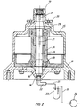
- the rotor 1 consists of a high-strength material which is rotationally symmetrical and which has receiving bores distributed around the circumference for receiving sample tubes 7.
- the sample tubes 7 are distributed at a uniform distance around the circumference of the rotor and are pushed through appropriately sealing sleeves 9 and rest with their lower, bottom-side surfaces a base 13 of the rotor, which is formed in the region of a circumferential annular groove 12.
- the rotor 1 is sealed from above by a cover 2, the cover 2 (not shown) being closed at the top by a button.
- the cover 2 forms a circumferential groove 3, in which an annular seal is inserted. This ring seal engages in a circumferential ring groove 4 in the rotor 1.
- a vacuum chamber 6 then forms between the underside of the lid 2 and the top of the rotor 1, into which the sample tubes 7 open with their upper open ends. Each sample tube 7 is filled with a sample liquid 17.
- connection part 19 of the rotary distributor 18 (FIG. 2) is connected and fastened in a sealing manner.
- the rotor is connected in a rotationally fixed manner to a motor bell 25 which engages over the rotary distributor 18.
- the sample tubes 7 through the sleeves 9 are carried out in a vacuum-tight manner.
- One or more sealing rings 10 can also be arranged in this area.
- the sample tubes also form a distance from the rotor wall 11, which slopes at an angle to the outside.
- the rotation distributor 18 has an annular flange 20 in the region of the moving connecting part 19, with which it is screwed onto the inside of the motor bell 25.
- the central bore 15 on the rotor, in which vacuum prevails, is via an axial bore 21 guided downwards in the rotating shaft 29 of the rotary distributor 18.
- the shaft 29 runs in seals 30 in order to prevent the inflow of incorrect air in this area.
- the bore 21 in the shaft 29 opens into an elbow 22 located below, which is connected via a line to a separator 23, which in turn is connected to a vacuum pump 24.
- the rotary drive takes place in that the motor is connected to a hub 26 which is rotatably held in bearings 28.
- the motor is also non-rotatably connected to the motor bell 25, which in turn is connected to the ring flange 20.
- the lower part of the rotary distributor is designed as a fixed housing 27.
- the rotor wall 11 can also be designed as a heat radiation source in that it is designed, for example, black or as a mirror surface.
- Another advantage is the low manufacturing costs, because there is no need for complex seals and in particular a magnetic coupling between a motor and that of the motor rotor to be driven 1.
- the invention only requires a small-sized and only relatively low-performance vacuum pump, oil lubrication of this vacuum pump can be dispensed with and therefore there is also no need for expensive separators and cold traps in the area of line 31, because when using a vacuum pump without Oil lubrication which can be flowed through by the solvent vapors without being damaged.
- the conductivity of the temperature transfer to the rotor is significantly improved. This enables better temperature control of the heating. This means that a temperature measurement in the rotor is not disturbed by the presence of a vacuum and is therefore easier to carry out.
Abstract
Description
Gegenstand der Erfindung ist eine Vakuum-Zentrifuge nach dem Oberbegriff des Patentanspruchs 1.The invention relates to a vacuum centrifuge according to the preamble of patent claim 1.
Derartige Vakuum-Zentrifugen sind z. B. durch Fertigungen der Fa. Savant bekannt geworden, bei denen im wesentlichen folgender Aufbau besteht. In einem vakuumdichten Kessel, der von oben über eine entsprechende Dichtung mit einem abnehmbaren Deckel verschließbar ist, rotiert ein Rotor, der eine Reihe von Probenröhrchen trägt, die zentrifugiert werden. Der Kessel wird evakuiert. Um eine Abdichtung des Kessels zu gewährleisten ist es bei der bekannten Ausführung erforderlich, den Rotor mit einem außen liegenden Motor über eine Magnetkupplung magnetisch zu koppeln, um so den Rotor im Kessel drehend anzutreiben.Such vacuum centrifuges are e.g. B. become known through productions from Savant, in which there is essentially the following structure. A rotor rotates in a vacuum-tight kettle, which can be closed from above by means of a corresponding seal with a removable lid, and carries a series of sample tubes that are centrifuged. The boiler is evacuated. In order to ensure that the boiler is sealed, it is necessary in the known embodiment to magnetically couple the rotor to an external motor via a magnetic coupling, so as to drive the rotor in the boiler in a rotating manner.
An der Innenseite des Kessels ist ferner eine Heizung vorhanden. Die Probenröhrchen sind nun mit einer Untersuchungsflüssigkeit und mit einem leicht flüchtigen Lösemittel befüllt, welches Lösemittel im Vakuum verdampft. Bei der Evakuierung des Kessels verdampft während des Zentrifugiervorganges somit das Lösemittel, welches über den Anschluß einer Vakuumpumpe am Kessel aus dem Kessel entfernt werden muß. Damit dieses gefährliche und agressive Lösemittel nicht die Vakuumpumpe beschädigt ist eine Kühlfalle vor der Vakuumpumpe angeordnet.There is also a heater on the inside of the boiler. The sample tubes are now filled with a test liquid and with a volatile solvent that evaporates the solvent in a vacuum. When the boiler is evacuated, the solvent evaporates during the centrifugation process and must be removed from the boiler by connecting a vacuum pump to the boiler. A cold trap is placed in front of the vacuum pump so that this dangerous and aggressive solvent does not damage the vacuum pump.
Nachteil der bekannten Vakuum-Zentrifuge ist, daß eine relativ aufwendige magnetische Kopplung zwischen dem Rotor und dem außen liegenden Motor erforderlich ist. Weiterer Nachteil ist, daß die im Innenraum des Kessels angeordnete Heizung nur ungenügend und mit geringem Wirkungsgrad die Probenröhrchen beheizen kann, denn die Beheizung kann nur über Infrarotstrahlung erfolgen; eine wärmeleitende Heizung durch einen entsprechenden Luftschleier fehlt. Daher ist die Heizung relativ träge.The disadvantage of the known vacuum centrifuge is that a relatively complex magnetic coupling between the rotor and the external motor is required. Another disadvantage is that the The heater arranged inside the boiler can only heat the sample tubes insufficiently and with little efficiency, because the heating can only be done via infrared radiation; there is no heat-conducting heating by means of an appropriate air curtain. The heating is therefore relatively slow.
Weiterer Nachteil ist der relativ aufwendige Aufbau der gesamten Anordnung, weil in dem Kessel das Lager für den Rotor in besonderer Weise ausgebildet sein muß und der Deckel den gesamten Kessel vakuumdicht abdecken muß.Another disadvantage is the relatively complex structure of the entire arrangement, because the bearing for the rotor must be designed in a special manner in the boiler and the cover must cover the entire boiler in a vacuum-tight manner.
Der Erfindung liegt deshalb die Aufgabe zugrunde, eine Vakuum-Zentrifuge der eingangs genannten Art so weiterzubilden, daß bei wesentlich geringerem Herstellungsaufwand ein betriebssicherer Betrieb der Vakuum-Zentrifuge gewährleistet ist.The invention is therefore based on the object of developing a vacuum centrifuge of the type mentioned in such a way that reliable operation of the vacuum centrifuge is ensured with substantially less production effort.
Zur Lösung der gestellten Aufgabe ist die Erfindung durch die technische Lehre des Anspruchs 1 gekennzeichnet.To achieve the object, the invention is characterized by the technical teaching of claim 1.
Wesentliches Merkmal der Erfindung ist, daß lediglich der Rotor an seiner Oberseite vakuumdicht mit einem Deckel verbunden ist, welcher Deckel in Verbindung mit der Rotorwandung einen innen liegenden Raum definiert, in den die öffnungen der Probenröhrchen münden, und daß ferner die Durchführung der Probenröhrchen durch den Rotor nach außen ebenfalls vakuumdicht abgedichtet ist.An essential feature of the invention is that only the top of the rotor is connected in a vacuum-tight manner to a lid, which lid, in conjunction with the rotor wall, defines an interior space into which the openings of the sample tubes open, and that the sample tubes are also passed through the The rotor is also sealed to the outside in a vacuum-tight manner.
Mit der gegebenen technischen Lehre wird der wesentliche Vorteil erreicht, daß nun der Rotor über eine herkömmliche, relativ kostengünstige mechanische Kupplung mit dem Motor direkt gekoppelt werden kann; es kann also auf eine magnetische Kupplung verzichtet werden. Weiterer Vorteil ist, daß nun nicht mehr der gesamte Kessel evakuiert werden muß, sondern daß nur noch ein geringer Teil (nämlich der obere Teil des Rotors) evakuiert wird. Damit kann das Vakuum wesentlich wirtschaftlicher hergestellt werden und die Vakuumpumpen brauchen keine so hohe Leistung aufzuweisen.With the given technical teaching, the main advantage is achieved that the rotor can now be coupled directly to the motor via a conventional, relatively inexpensive mechanical coupling; there is therefore no need for a magnetic coupling. Another advantage is that it is no longer necessary to evacuate the entire boiler, but only a small part (namely the upper part of the rotor) is evacuated. This means that the vacuum can be produced much more economically and the vacuum pumps do not have to be as powerful.
Ein weiterer wesentlicher Vorteil der Erfindung ist, daß die an der Innenseite des Kessels angeordnete Heizung nun mit gutem Wirkungsgrad und schneller Reaktionszeit die Probenröhrchen beheizen kann. Der Kessel ist erfindungsgemäß nicht mehr evakuiert, sondern es besteht ein üblicher Luftschleier im Kessel, der zu einer schnellen Verteilung der Heizungswärme auf die Probenröhrchen führt.Another important advantage of the invention is that the heater arranged on the inside of the boiler can now heat the sample tubes with good efficiency and a fast reaction time. According to the invention, the boiler is no longer evacuated, but there is a conventional air curtain in the boiler, which leads to a rapid distribution of the heating heat to the sample tubes.
Außerdem kann die Außenwandung des Rotors, an der nächstliegend die Röhrchen beabstandet sind, schwarz eloxiert werden, um so den Rotor als Wärmestrahlungsquelle auszubilden, welche die Wärme schnell auf die Probenröhrchen überträgt.In addition, the outer wall of the rotor, on which the tubes are spaced next to one another, can be black anodized, so as to design the rotor as a heat radiation source which quickly transfers the heat to the sample tubes.
Damit ist es nun möglich, mit einer schnell wirksamen Heizung unter Vakuum den Inhalt der Probenröhrchen zu evakuieren und somit die im Innenraum der Probenröhrchen angeordnete Lösemittel-Flüssigkeit schnell zu verdampfen.It is now possible to evacuate the contents of the sample tubes with a quick-acting heater under vacuum and thus to quickly evaporate the solvent liquid arranged in the interior of the sample tubes.
Ein weiterer Vorteil der Erfindung liegt darin, daß nun mit einem an sich bekannten Rotationsverteiler die Lösemitteldämpfe aus dem oberen, evakuierten Teil des Rotors leicht entfernt werden können. Hierzu wird der Rotationsverteiler verwendet, der in der Achse des Rotors angeordnet ist und der entsprechende Drehdichtungen aufweist, über welche die gefährlichen Lösemitteldämpfe nach unten axial durch die Rotorachse hinweg abgesaugt werden. Wegen des geringeren Absaugvolumens können daher Vakuumpumpen mit relativ geringer Leistungsfähigkeit verwendet werden, die dementsprechend kostengünstig ausgebildet sind.Another advantage of the invention is that the solvent vapors can now be easily removed from the upper, evacuated part of the rotor using a rotary distributor known per se. For this purpose, the rotation distributor is used, which is arranged in the axis of the rotor and which has corresponding rotary seals, via which the dangerous solvent vapors are sucked off axially downward through the rotor axis. Because of the lower suction volume, vacuum pumps with a relatively low performance can therefore be used, which are accordingly inexpensive.
Kern der vorliegenden Erfindung ist also, daß die Vakuumkammer im Rotor angeordnet ist und nicht mehr im Kessel. Damit rotiert die Vakuumkammer mit dem Rotor mit, während beim Stand der Technik die Vakuumkammer im Kessel selbst ausgebildet ist und nicht mit rotiert.The essence of the present invention is that the vacuum chamber in the rotor is arranged and no longer in the boiler. The vacuum chamber thus rotates with the rotor, while in the prior art the vacuum chamber is formed in the boiler itself and does not rotate with it.
Der Erfindungsgegenstand der vorliegenden Erfindung ergibt sich nicht nur aus dem Gegenstand der einzelnen Patentansprüche, sondern auch aus der Kombination der einzelnen Patentansprüche untereinander. Alle in den Unterlagen - einschließlich der Zusammenfassung - offenbarten Angaben und Merkmale, insbesondere die in den Zeichnungen dargestellte räumliche Ausbildung werden als erfindungswesentlich beansprucht, soweit sie einzeln oder in Kombination gegenüber dem Stand der Technik neu sind.The subject matter of the present invention results not only from the subject matter of the individual patent claims, but also from the combination of the individual patent claims with one another. All of the information and features disclosed in the documents - including the summary -, in particular the spatial design shown in the drawings, are claimed to be essential to the invention, insofar as they are new compared to the prior art, individually or in combination.
Im folgenden wird die Erfindung anhand von lediglich einen Ausführungsweg darstellende Zeichnungen näher erläutert. Hierbei gehen aus den Zeichnungen und ihrer Beschreibung weitere erfindungswesentliche Merkmale und Vorteile der Erfindung hervor.The invention is explained in more detail below with the aid of drawings which illustrate only one embodiment. Here, from the drawings and their description, further features and advantages of the invention that are essential to the invention emerge.
Es zeigen:
- Figur 1:
- schematisiert einen Schnitt durch einen Rotor nach der Erfindung,
- Figur 2:
- Schnitt durch einen Rotationsverteiler mit Antriebsmotor, der den Rotor nach Figur 1 antreibt.
- Figure 1:
- schematized a section through a rotor according to the invention,
- Figure 2:
- Section through a rotary distributor with a drive motor which drives the rotor according to Figure 1.
Der Rotor 1 nach Figur 1 besteht aus einem hochfesten Material, welches rotationssymmetrisch ausgebildet ist und welches am Umfang verteilt Aufnahmebohrungen für die Aufnahme von Probenröhrchen 7 aufweist. Die Probenröhrchen 7 sind in gleichmäßigem Abstand am Umfang des Rotors verteilt durch entsprechend abdichtend ausgebildete Hülsen 9 hindurchgesteckt und ruhen mit ihren unteren bodenseitigen Flächen auf einer Standfläche 13 des Rotors, die im Bereich einer umlaufenden Ringnut 12 ausgebildet ist. Der Rotor 1 ist von oben her durch einen Deckel 2 abgedichtet, wobei der Deckel 2 (nicht gezeigt) nach oben noch durch einen Knopf abgeschlossen ist. Der Deckel 2 bildet eine umlaufende Nut 3, in welche eine Ringdichtung eingelegt ist. Diese Ringdichtung greift in eine umlaufende Ringnut 4 im Rotor 1 ein. Durch Einschrauben des Knopfes am Deckel 2 an den Rotor wird somit der Deckel 2 vakuumdicht auf die Oberseite des Rotors 1 aufgeschraubt und abgedichtet. Es bildet sich dann zwischen der Unterseite des Deckels 2 und der Oberseite des Rotors 1 eine Vakuumkammer 6, in welche die Probenröhrchen 7 mit ihren oberen offenen Enden hineinmünden. Jedes Probenröhrchen 7 ist mit einer Probeflüssigkeit 17 gefüllt.The rotor 1 according to FIG. 1 consists of a high-strength material which is rotationally symmetrical and which has receiving bores distributed around the circumference for receiving
Von der Vakuumkammer 6 münden am Umfang verteilt radial einwärts gerichtete Bohrungen 8 nach innen, und laufen dort in axial gerichtete Bohrungen 16 ein, die in einer zentralen Bohrung 15 münden. In diesem Bereich wird das Anschlußteil 19 des Rotationsverteilers 18 (Figur 2) angeschlossen und abdichtend befestigt.From the
Der Rotor ist mit einer Motorglocke 25 drehfest verbunden, welche Motorglocke 25 den Rotationsverteiler 18 übergreift.The rotor is connected in a rotationally fixed manner to a
Wichtig ist, daß die Durchführung der Probenröhrchen 7 durch die Hülsen 9 vakuumdicht ausgeführt ist, in diesem Bereich können noch ein oder mehrere Dichtringe 10 angeordnet sein. Die Probenröhrchen bilden im Ubrigen einen Abstand zu der schräg nach außen geneigt verlaufenden Rotorwand 11.It is important that the passage of the
Der Rotationsverteiler 18 weist im Bereich des mitlaufenden Anschlußteiles 19 einen Ringflansch 20 auf, mit dem dieser an der Innenseite der Motorglocke 25 angeschraubt wird. Die zentrale Bohrung 15 am Rotor, in welcher Vakuum herrscht, wird über eine axiale Bohrung 21 in der mitlaufenden Welle 29 des Rotationsverteilers 18 nach unten geführt. Die Welle 29 läuft in Dichtungen 30, um in diesem Bereich ein Einströmen von Fehlluft zu vermeiden. Die Bohrung 21 in der Welle 29 mündet in einen unten liegenden Krümmer 22, der über eine Leitung mit einem Abscheider 23 verbunden ist, der seinerseits mit einer Vakuumpumpe 24 verbunden ist.The
Der Drehantrieb erfolgt dadurch, daß der Motor mit einer Nabe 26 verbunden ist, die in Lagern 28 drehbar gehalten ist. Der Motor ist ferner mit der Motorglocke 25 drehfest verbunden, welche ihrerseits mit dem Ringflansch 20 verbunden ist.The rotary drive takes place in that the motor is connected to a
Der untere Teil des Rotationsverteilers ist als feststehendes Gehäuse 27 ausgebildet.The lower part of the rotary distributor is designed as a
Mit der gegebenen technische Lehre ergibt sich also der wesentliche Vorteil, daß mit einer Vakuumpumpe 24 relativ geringer Leistungsfähigkeit eine Vakuumkammer 6 mit nur geringem Volumen evakuiert werden muß. Außerderm ergibt sich der Vorteil, daß an der Innenseite des (nicht näher dargestellten) Kessels eine wirksame Heizung angebracht werden kann, weil die Probenröhrchen 7 in dem mit Luft gefüllten Innenraum des Kessels laufen und damit ein ständig wirbelnder Luftschleier erzeugt wird, der die Heizungswärme gut auf die Probenröhrchen 7 überträgt.With the given technical teaching there is the essential advantage that a
Außerdem kann die Rotorwand 11 noch als Wärmestrahlungsquelle dadurch ausgebildet sein, daß sie beispielsweise schwarz oder als Spiegelfläche ausgebildet ist.In addition, the
Weiterer Vorteil sind die geringen Herstellungskosten, denn es kann auf aufwendige Abdichtungen verzichtet werden und insbesondere auf eine magnetische Kupplung zwischen einem Motor und dem vom Motor anzutreibenden Rotor 1.Another advantage is the low manufacturing costs, because there is no need for complex seals and in particular a magnetic coupling between a motor and that of the motor rotor to be driven 1.
Es entfällt also somit auch eine aufwendige separate Lagerung des Rotors im Kessel einer Zentrifuge.So there is also no need for an expensive separate bearing of the rotor in the bowl of a centrifuge.
Im Stand der Technik werden aufwendige, ölgeschmierte Vakuumpumpen hoher Leistungsfähigkeit verwendet, die das relativ große Volumen im Kessel evakuieren können. Aus diesem Grunde ist beim Stand der Technik die Anordnung von Kühlfallen und Abscheidern erforderlich, um die mit ölgeschmierten Vakuumpumpen vor den agressiven Lösemitteldämpfen zu schützen.In the prior art, complex, oil-lubricated vacuum pumps of high performance are used, which can evacuate the relatively large volume in the boiler. For this reason, the arrangement of cooling traps and separators is required in the prior art in order to protect the oil-lubricated vacuum pumps from the aggressive solvent vapors.
Weil bei der Erfindung aber nur eine kleinbauende und nur eine relativ geringe Leistungsfähigkeit aufweisende Vakuumpumpe benötigt wird, kann auf eine ölschmierung dieser Vakuumpumpe verzichtet werden und daher kann auch auf aufwendige Abscheider und Kühlfallen im Bereich der Leitung 31 verzichtet werden, weil bei Verwendung einer Vakuumpumpe ohne ölschmierung diese von den Lösemitteldämpfen durchströmt werden kann, ohne Schaden zu nehmen.However, because the invention only requires a small-sized and only relatively low-performance vacuum pump, oil lubrication of this vacuum pump can be dispensed with and therefore there is also no need for expensive separators and cold traps in the area of
Nachdem der Kessel und die übrigen Flächen des Rotors unter Atmosphärendruck stehen und mit Luft beaufschlagt sind, ist die Leitfähigkeit der Temperaturübertragung auf den Rotor wesentlich verbessert. Damit ist eine bessere Temperaturregelung der Heizung möglich. Damit ist auch eine Temperaturmessung im Rotor nicht gestört durch Vorhandensein eines Vakuums und ist deshalb einfacher durchzuführen.

Claims (14)
dadurch gekennzeichnet, daß die Vakuumkammer (6) im Rotor (1) angeordnet ist und mittels eines koaxial zur Rotorachse vorgesehenen Ableitungssystems (16;21;22) mit der Vakuum-Pumpeneinrichtung (23;24) verbunden ist.
characterized in that the vacuum chamber (6) is arranged in the rotor (1) and is connected to the vacuum pump device (23; 24) by means of a discharge system (16; 21; 22) provided coaxially to the rotor axis.
Applications Claiming Priority (2)
| Application Number | Priority Date | Filing Date | Title |
|---|---|---|---|
| DE4233753A DE4233753C2 (en) | 1992-10-07 | 1992-10-07 | Vacuum centrifuge |
| DE4233753 | 1992-10-07 |
Publications (3)
| Publication Number | Publication Date |
|---|---|
| EP0592354A2 true EP0592354A2 (en) | 1994-04-13 |
| EP0592354A3 EP0592354A3 (en) | 1994-11-09 |
| EP0592354B1 EP0592354B1 (en) | 1997-07-09 |
Family
ID=6469880
Family Applications (1)
| Application Number | Title | Priority Date | Filing Date |
|---|---|---|---|
| EP93710015A Expired - Lifetime EP0592354B1 (en) | 1992-10-07 | 1993-09-07 | Vacuum-centrifuge |
Country Status (2)
| Country | Link |
|---|---|
| EP (1) | EP0592354B1 (en) |
| DE (2) | DE4233753C2 (en) |
Cited By (7)
| Publication number | Priority date | Publication date | Assignee | Title |
|---|---|---|---|---|
| GB2332865A (en) * | 1997-12-23 | 1999-07-07 | Michael Cole | Vacuum centrifugal evaporator |
| GB2341811A (en) * | 1998-09-05 | 2000-03-29 | Michael Cole | Centrifugal evaporator with load sensor |
| GB2345655A (en) * | 1998-11-12 | 2000-07-19 | Michael Cole | Centrufugal evaporator |
| WO2000047976A1 (en) * | 1999-02-09 | 2000-08-17 | Genevac Limited | Heating method for evaporators |
| WO2014029458A1 (en) * | 2012-08-24 | 2014-02-27 | Sigma Laborzentrifugen Gmbh | Rotor for a laboratory centrifuge |
| CN104646192A (en) * | 2015-02-05 | 2015-05-27 | 郭建中 | Medical centrifuge |
| CN110076010A (en) * | 2019-04-28 | 2019-08-02 | 浙江大学 | Superelevation gravity geotechnique's centrifugal device vacuum cavity structure |
Citations (6)
| Publication number | Priority date | Publication date | Assignee | Title |
|---|---|---|---|---|
| DE600884C (en) * | 1932-11-30 | 1934-08-02 | Hans Richter Dr | Centrifuge vessel with collecting attachment |
| FR2156519A1 (en) * | 1971-10-08 | 1973-06-01 | Immuno Ag | Bench centrifuge - having separate supports for test tubes and microtitration plates |
| DE2364701A1 (en) * | 1973-03-26 | 1974-10-10 | Zentrifugenbau Engelsdorf Veb | Contactless temp measurement of centrifuge rotors - plate with radiation absorbing layer and thermosensitive element attains rotor temp and transmits value |
| DE3805894C1 (en) * | 1988-02-25 | 1989-03-23 | Heraeus Sepatech Gmbh, 3360 Osterode, De | Fixed angle rotor for laboratory centrifuges |
| US4857811A (en) * | 1988-03-31 | 1989-08-15 | E. I. Du Pont De Nemours And Company | Evacuation pump control for a centrifuge instrument |
| GB2230203A (en) * | 1989-03-20 | 1990-10-17 | Jouan | Use of centrifugal evaporator-concentrator to concentrate specimens |
Family Cites Families (4)
| Publication number | Priority date | Publication date | Assignee | Title |
|---|---|---|---|---|
| US3819111A (en) * | 1973-04-09 | 1974-06-25 | Sorvall Inc Ivan | Centrifuge rotor cover |
| US4226669A (en) * | 1979-05-09 | 1980-10-07 | Savant Instruments, Inc. | Vacuum centrifuge with magnetic drive |
| US4693702A (en) * | 1986-08-04 | 1987-09-15 | E.I. Du Pont De Nemours And Company | Rotor having frangible projections thereon |
| DE3768808D1 (en) * | 1987-06-20 | 1991-04-25 | Eppendorf Geraetebau Netheler | CENTRIFUGAL ROTOR. |
-
1992
- 1992-10-07 DE DE4233753A patent/DE4233753C2/en not_active Expired - Fee Related
-
1993
- 1993-09-07 DE DE59306871T patent/DE59306871D1/en not_active Expired - Fee Related
- 1993-09-07 EP EP93710015A patent/EP0592354B1/en not_active Expired - Lifetime
Patent Citations (6)
| Publication number | Priority date | Publication date | Assignee | Title |
|---|---|---|---|---|
| DE600884C (en) * | 1932-11-30 | 1934-08-02 | Hans Richter Dr | Centrifuge vessel with collecting attachment |
| FR2156519A1 (en) * | 1971-10-08 | 1973-06-01 | Immuno Ag | Bench centrifuge - having separate supports for test tubes and microtitration plates |
| DE2364701A1 (en) * | 1973-03-26 | 1974-10-10 | Zentrifugenbau Engelsdorf Veb | Contactless temp measurement of centrifuge rotors - plate with radiation absorbing layer and thermosensitive element attains rotor temp and transmits value |
| DE3805894C1 (en) * | 1988-02-25 | 1989-03-23 | Heraeus Sepatech Gmbh, 3360 Osterode, De | Fixed angle rotor for laboratory centrifuges |
| US4857811A (en) * | 1988-03-31 | 1989-08-15 | E. I. Du Pont De Nemours And Company | Evacuation pump control for a centrifuge instrument |
| GB2230203A (en) * | 1989-03-20 | 1990-10-17 | Jouan | Use of centrifugal evaporator-concentrator to concentrate specimens |
Cited By (14)
| Publication number | Priority date | Publication date | Assignee | Title |
|---|---|---|---|---|
| GB2332865B (en) * | 1997-12-23 | 1999-12-29 | Michael Cole | Improved evaporator and evaporation process |
| GB2332865A (en) * | 1997-12-23 | 1999-07-07 | Michael Cole | Vacuum centrifugal evaporator |
| US6682631B2 (en) | 1997-12-23 | 2004-01-27 | Genevac Limited | Evaporator and evaporation process |
| GB2341811B (en) * | 1998-09-05 | 2002-04-17 | Michael Cole | Control of weight during evaporation of samples |
| GB2341811A (en) * | 1998-09-05 | 2000-03-29 | Michael Cole | Centrifugal evaporator with load sensor |
| GB2345655A (en) * | 1998-11-12 | 2000-07-19 | Michael Cole | Centrufugal evaporator |
| WO2000047976A1 (en) * | 1999-02-09 | 2000-08-17 | Genevac Limited | Heating method for evaporators |
| WO2014029458A1 (en) * | 2012-08-24 | 2014-02-27 | Sigma Laborzentrifugen Gmbh | Rotor for a laboratory centrifuge |
| CN104039459A (en) * | 2012-08-24 | 2014-09-10 | 希格玛实验室离心机有限公司 | Rotor for laboratory centrifuge |
| US9079195B2 (en) | 2012-08-24 | 2015-07-14 | Sigma Laborzentrifugen Gmbh | Rotor for a laboratory centrifuge with rotor hub cooling means |
| CN104039459B (en) * | 2012-08-24 | 2017-04-19 | 希格玛实验室离心机有限公司 | Rotor for laboratory centrifuge |
| CN104646192A (en) * | 2015-02-05 | 2015-05-27 | 郭建中 | Medical centrifuge |
| CN110076010A (en) * | 2019-04-28 | 2019-08-02 | 浙江大学 | Superelevation gravity geotechnique's centrifugal device vacuum cavity structure |
| CN110076010B (en) * | 2019-04-28 | 2023-08-11 | 浙江大学 | Vacuum cavity structure of ultra-high gravity geotechnical centrifugal device |
Also Published As
| Publication number | Publication date |
|---|---|
| DE4233753A1 (en) | 1994-04-21 |
| DE59306871D1 (en) | 1997-08-14 |
| EP0592354A3 (en) | 1994-11-09 |
| DE4233753C2 (en) | 1998-01-29 |
| EP0592354B1 (en) | 1997-07-09 |
Similar Documents
| Publication | Publication Date | Title |
|---|---|---|
| EP0387278B1 (en) | Overlapping filter centrifuge | |
| EP1603679A1 (en) | Inverting filter centrifuge | |
| WO2002078852A1 (en) | Screen centrifuge | |
| DE19646038C2 (en) | Inverting filter centrifuge | |
| DE102013100180A1 (en) | separator arrangement | |
| EP0592354B1 (en) | Vacuum-centrifuge | |
| CH619150A5 (en) | ||
| DE1261345B (en) | Ultracentrifuge with continuous liquid circulation | |
| DE3307572A1 (en) | SAMPLE TURNING DEVICE | |
| DE69830200T2 (en) | EXPANSION PROCESS | |
| WO1992004982A1 (en) | Reverse filter centrifugal machine | |
| EP0444443A1 (en) | Freeze-drying apparatus | |
| DE2656271A1 (en) | DRY SPIN WITH AXIAL THRUST | |
| DE2401883A1 (en) | DEVICE FOR INDIRECT HEAT TREATMENT OF LIQUIDS | |
| DE3114449A1 (en) | Sealing system for a rotary evaporator | |
| DE2509386A1 (en) | DEVICE FOR A MACHINE ELEMENT WITH A CLOSED HOUSING | |
| DE4325667A1 (en) | Vessel arrangement having a vessel for evaporative treatment or for the preparation and analysis of materials | |
| WO2004062806A1 (en) | Reaction chamber system for processing samples | |
| DE3425706C2 (en) | Refrigerated centrifuge | |
| DE2603480A1 (en) | Continuous rotary thin-layer evaporator - having hollow rotor contg. heat transfer fluid which is electrically heated | |
| DE2748835A1 (en) | CENTRIFUGAL SPRAYER FOR USE IN SPRAY DRYING SYSTEMS | |
| DE3430508A1 (en) | Filter centrifuge | |
| DE2657956C2 (en) | Thin film evaporator, especially for high-boiling products | |
| DE2362795C3 (en) | Electric ring motor for driving an agitator intended for a container | |
| CH269791A (en) | Device for high vacuum distillation. |
Legal Events
| Date | Code | Title | Description |
|---|---|---|---|
| PUAI | Public reference made under article 153(3) epc to a published international application that has entered the european phase |
Free format text: ORIGINAL CODE: 0009012 |
|
| AK | Designated contracting states |
Kind code of ref document: A2 Designated state(s): DE FR GB IT |
|
| PUAL | Search report despatched |
Free format text: ORIGINAL CODE: 0009013 |
|
| AK | Designated contracting states |
Kind code of ref document: A3 Designated state(s): DE FR GB IT |
|
| 17P | Request for examination filed |
Effective date: 19950328 |
|
| GRAG | Despatch of communication of intention to grant |
Free format text: ORIGINAL CODE: EPIDOS AGRA |
|
| 17Q | First examination report despatched |
Effective date: 19961118 |
|
| GRAH | Despatch of communication of intention to grant a patent |
Free format text: ORIGINAL CODE: EPIDOS IGRA |
|
| GRAH | Despatch of communication of intention to grant a patent |
Free format text: ORIGINAL CODE: EPIDOS IGRA |
|
| GRAA | (expected) grant |
Free format text: ORIGINAL CODE: 0009210 |
|
| AK | Designated contracting states |
Kind code of ref document: B1 Designated state(s): DE FR GB IT |
|
| REF | Corresponds to: |
Ref document number: 59306871 Country of ref document: DE Date of ref document: 19970814 |
|
| ITF | It: translation for a ep patent filed |
Owner name: STUDIO CECILIA COPPI |
|
| ET | Fr: translation filed | ||
| GBT | Gb: translation of ep patent filed (gb section 77(6)(a)/1977) |
Effective date: 19971006 |
|
| PLBE | No opposition filed within time limit |
Free format text: ORIGINAL CODE: 0009261 |
|
| STAA | Information on the status of an ep patent application or granted ep patent |
Free format text: STATUS: NO OPPOSITION FILED WITHIN TIME LIMIT |
|
| 26N | No opposition filed | ||
| PGFP | Annual fee paid to national office [announced via postgrant information from national office to epo] |
Ref country code: GB Payment date: 19980904 Year of fee payment: 6 Ref country code: DE Payment date: 19980904 Year of fee payment: 6 |
|
| PGFP | Annual fee paid to national office [announced via postgrant information from national office to epo] |
Ref country code: FR Payment date: 19980929 Year of fee payment: 6 |
|
| PG25 | Lapsed in a contracting state [announced via postgrant information from national office to epo] |
Ref country code: GB Free format text: LAPSE BECAUSE OF NON-PAYMENT OF DUE FEES Effective date: 19990907 |
|
| GBPC | Gb: european patent ceased through non-payment of renewal fee |
Effective date: 19990907 |
|
| PG25 | Lapsed in a contracting state [announced via postgrant information from national office to epo] |
Ref country code: FR Free format text: LAPSE BECAUSE OF NON-PAYMENT OF DUE FEES Effective date: 20000531 |
|
| PG25 | Lapsed in a contracting state [announced via postgrant information from national office to epo] |
Ref country code: DE Free format text: LAPSE BECAUSE OF NON-PAYMENT OF DUE FEES Effective date: 20000701 |
|
| REG | Reference to a national code |
Ref country code: FR Ref legal event code: ST |
|
| PG25 | Lapsed in a contracting state [announced via postgrant information from national office to epo] |
Ref country code: IT Free format text: LAPSE BECAUSE OF NON-PAYMENT OF DUE FEES;WARNING: LAPSES OF ITALIAN PATENTS WITH EFFECTIVE DATE BEFORE 2007 MAY HAVE OCCURRED AT ANY TIME BEFORE 2007. THE CORRECT EFFECTIVE DATE MAY BE DIFFERENT FROM THE ONE RECORDED. Effective date: 20050907 |