EP0592266A1 - Rod locking device, especially for osteosynthesis or arthrodesis - Google Patents
Rod locking device, especially for osteosynthesis or arthrodesis Download PDFInfo
- Publication number
- EP0592266A1 EP0592266A1 EP93402297A EP93402297A EP0592266A1 EP 0592266 A1 EP0592266 A1 EP 0592266A1 EP 93402297 A EP93402297 A EP 93402297A EP 93402297 A EP93402297 A EP 93402297A EP 0592266 A1 EP0592266 A1 EP 0592266A1
- Authority
- EP
- European Patent Office
- Prior art keywords
- head
- bar
- rod
- connecting element
- jumper
- Prior art date
- Legal status (The legal status is an assumption and is not a legal conclusion. Google has not performed a legal analysis and makes no representation as to the accuracy of the status listed.)
- Ceased
Links
Images
Classifications
-
- A—HUMAN NECESSITIES
- A61—MEDICAL OR VETERINARY SCIENCE; HYGIENE
- A61B—DIAGNOSIS; SURGERY; IDENTIFICATION
- A61B17/00—Surgical instruments, devices or methods, e.g. tourniquets
- A61B17/56—Surgical instruments or methods for treatment of bones or joints; Devices specially adapted therefor
- A61B17/58—Surgical instruments or methods for treatment of bones or joints; Devices specially adapted therefor for osteosynthesis, e.g. bone plates, screws, setting implements or the like
- A61B17/68—Internal fixation devices, including fasteners and spinal fixators, even if a part thereof projects from the skin
- A61B17/70—Spinal positioners or stabilisers ; Bone stabilisers comprising fluid filler in an implant
- A61B17/7001—Screws or hooks combined with longitudinal elements which do not contact vertebrae
- A61B17/7035—Screws or hooks, wherein a rod-clamping part and a bone-anchoring part can pivot relative to each other
- A61B17/704—Screws or hooks, wherein a rod-clamping part and a bone-anchoring part can pivot relative to each other the longitudinal element passing through a ball-joint in the screw head
-
- A—HUMAN NECESSITIES
- A61—MEDICAL OR VETERINARY SCIENCE; HYGIENE
- A61B—DIAGNOSIS; SURGERY; IDENTIFICATION
- A61B17/00—Surgical instruments, devices or methods, e.g. tourniquets
- A61B17/56—Surgical instruments or methods for treatment of bones or joints; Devices specially adapted therefor
- A61B17/58—Surgical instruments or methods for treatment of bones or joints; Devices specially adapted therefor for osteosynthesis, e.g. bone plates, screws, setting implements or the like
- A61B17/68—Internal fixation devices, including fasteners and spinal fixators, even if a part thereof projects from the skin
- A61B17/84—Fasteners therefor or fasteners being internal fixation devices
- A61B17/86—Pins or screws or threaded wires; nuts therefor
- A61B17/8695—Washers
-
- A—HUMAN NECESSITIES
- A61—MEDICAL OR VETERINARY SCIENCE; HYGIENE
- A61F—FILTERS IMPLANTABLE INTO BLOOD VESSELS; PROSTHESES; DEVICES PROVIDING PATENCY TO, OR PREVENTING COLLAPSING OF, TUBULAR STRUCTURES OF THE BODY, e.g. STENTS; ORTHOPAEDIC, NURSING OR CONTRACEPTIVE DEVICES; FOMENTATION; TREATMENT OR PROTECTION OF EYES OR EARS; BANDAGES, DRESSINGS OR ABSORBENT PADS; FIRST-AID KITS
- A61F2/00—Filters implantable into blood vessels; Prostheses, i.e. artificial substitutes or replacements for parts of the body; Appliances for connecting them with the body; Devices providing patency to, or preventing collapsing of, tubular structures of the body, e.g. stents
- A61F2/02—Prostheses implantable into the body
- A61F2/30—Joints
- A61F2002/30001—Additional features of subject-matter classified in A61F2/28, A61F2/30 and subgroups thereof
- A61F2002/30316—The prosthesis having different structural features at different locations within the same prosthesis; Connections between prosthetic parts; Special structural features of bone or joint prostheses not otherwise provided for
- A61F2002/30329—Connections or couplings between prosthetic parts, e.g. between modular parts; Connecting elements
- A61F2002/30383—Connections or couplings between prosthetic parts, e.g. between modular parts; Connecting elements made by laterally inserting a protrusion, e.g. a rib into a complementarily-shaped groove
- A61F2002/30387—Dovetail connection
-
- A—HUMAN NECESSITIES
- A61—MEDICAL OR VETERINARY SCIENCE; HYGIENE
- A61F—FILTERS IMPLANTABLE INTO BLOOD VESSELS; PROSTHESES; DEVICES PROVIDING PATENCY TO, OR PREVENTING COLLAPSING OF, TUBULAR STRUCTURES OF THE BODY, e.g. STENTS; ORTHOPAEDIC, NURSING OR CONTRACEPTIVE DEVICES; FOMENTATION; TREATMENT OR PROTECTION OF EYES OR EARS; BANDAGES, DRESSINGS OR ABSORBENT PADS; FIRST-AID KITS
- A61F2220/00—Fixations or connections for prostheses classified in groups A61F2/00 - A61F2/26 or A61F2/82 or A61F9/00 or A61F11/00 or subgroups thereof
- A61F2220/0025—Connections or couplings between prosthetic parts, e.g. between modular parts; Connecting elements
Definitions
- the present invention relates to devices for immobilizing a bar relative to a bone part with a view, for example, to carrying out an osteosynthesis or an arthrodesis, in particular spinal, that is to say the devices which allow, by means at least one bar and fixing means, to make a connection between two bones such as, for example, two vertebrae of a spine.
- Such a device is for example described in Patent DE-A-4,107,480. It essentially comprises a rod and a head with two opposite faces, a rider in the shape of a substantially "U” comprising at least one base and two integral lateral branches from the base at one of their ends, two hooks mounted respectively on the free end of the two lateral branches, laterally to these branches, towards the inside of the "U” and substantially facing one another, and means for exerting a couple of opposite forces between the rider and the head via the bar so as to join together the rider, the head and the bar.
- This known device makes it possible to fix a bar to obtain a spinal arthrodesis, but has the disadvantage of making it very difficult sometimes to align the connecting bar with respect to the vertebrae.
- the present invention thus aims to achieve a device for immobilizing a bar relative to a bone part in order, for example, to perform an osteosynthesis or arthrodesis, in particular spinal, which obviates the drawbacks mentioned above.
- the subject of the present invention is a device for immobilizing a bar with respect to a bone part with a view, for example, to carrying out an osteosynthesis or an arthrodesis, in particular spinal, comprising fixing means, these means comprising a rod and a head with two substantially opposite faces, said rod being integral with one of the two faces of said head and capable of being linked directly or indirectly to said bone part, a rider in the shape of a substantially "U” comprising at least a base and two lateral branches integral with said base, two hooks mounted respectively on the free end of the two lateral branches, said hooks being mounted laterally at the free ends of the two said branches, towards the inside of said "U” and substantially in looking at each other, and means for exerting a couple of opposite forces between said rider and said head by means of said bar so as to join together said rider, said head and said bar, characterized by the fact that the distance separating the two said hooks is less than the width of at least part of said head and greater than the section of said rod and said fixing means
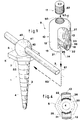
- Figures 1 and 2 show an embodiment of a device 1 for immobilizing a bar 2 for, in particular, osteosynthesis or spinal arthrodesis.
- This device comprises fixing means 3 on a bone part 8, these means comprising a rod 4 and a head 5 with two faces 6, 7 substantially opposite, the section of the head being greater than the section of the rod, the rod 4 is integral with one 7 of the two faces of the head and it is capable of being linked directly or indirectly to the bone part 8, for example by screwing when it is threaded or by any other suitable means.
- the device also comprises means 9 for securing the bar 2 with the head 5.
- These means 9 for securing the bar 2 with the head 5 comprise a jumper 10 substantially in the shape of a "U" comprising at least one base 11 and at least two lateral branches 12, 13 integral with this base 11, hooking means 14 the free end 15, 16 of the two lateral branches 12, 13 of the jumper 10 not secured to the base 11, with the head 5, and means 17 for exerting a couple of opposite forces between the jumper 10 and the head 5 by through the bar 2 so as to secure the jumper 10 together, the head 5 and bar 2.
- the hooking means 14 of the free end 15, 16 of the two lateral branches 12, 13 of the jumper 10 not secured to the base 11, with the head 5, comprise two hooks 21, 22 mounted respectively on the free end 15, 16 of the two lateral branches 12, 13.
- These hooks 21, 22 are mounted laterally at the free ends 15, 16 towards the inside 23 of the "U” and substantially facing one of the other, the distance separating them being less than the width of at least part of the head 5 and greater than the cross section of the rod 4 and of the bar 2, the distance internally separating the two lateral branches 12, 13 and the depth 23 of the "U” being greater than the section of the bar 2, this section being constituted by the diameter of the bar in the most advantageous case where this bar is cylindrical of revolution.
- the head 5 can be introduced between the two branches of the rider before being secured with their free end and so that the rider 10 and the head 5 can at least slightly pivot with respect to each other substantially around the axis of the rod 4, at least part of the head, if not all, has a width, taken in a direction perpendicular to the axis of the rod 4, less than the distance internally separating the two branches side of the rider.
- the hooking means 14 of the free end 15, 16 of the two lateral branches 12, 13 of the jumper 10, with the head 5, further comprise a projecting part 25, 26 on each of the hooks 21, 22, these parts 25, 26 projecting towards the bottom 27 of the "U".
- this head advantageously comprises a hollow groove 30 produced on its face 7 secured to the rod 4 and of a section substantially complementary to that of the projecting parts 25, 26.
- this groove 30 and the projecting parts 25, 26 are defined on two substantially circular lines of the same radius, as shown in FIG. 4, so as to obtain perfect engagement of the projecting parts 25, 26 in the groove 30 whatever the relative angular positions of the head 5 and the jumper 10.
- section of the groove 30 and the projecting parts 25, 26 is advantageously triangular or of a shape which can be assimilated to a triangular shape or the like, in order to obtain an engagement of the conical type. and promote strong coupling and rigid between head 5 and jumper 10.
- the example of the jumper 10 illustrated in particular in FIG. 1 is a preferred embodiment for most cases of use of the device.
- the jumper can be made so that its two lateral branches 12, 13 are interconnected on one of the two faces of the "U” by a wall near the ends 15, 16 not integral with the base 11. It is only necessary that, in this wall, an opening is defined which allows the passage of the bar 2 and the translation of the jumper 10 along its axis 51 so that the hooking means 14 can cooperate with the head 5.
- the means 17 for exerting a couple of opposite forces between the jumper 10 and the head 5 by means of the bar 2 so as to secure the jumper 10 together , the head 5 and the bar 2 comprise a connecting element 40 at least partially surrounding the bar 2 and advantageously deformable.
- this connecting element 40 is located between the two lateral branches 12, 13 of the jumper 10 and rests on the face 6 of the head 5 opposite to the face 7 secured to the rod 4.
- this connecting element 40 has, by its external surface 41, a substantially spherical shape with a diameter slightly less than the distance internally separating the two lateral branches 12, 13 and comprises a diametrical breakthrough 42 of a substantially equal section or slightly larger than the cross section of the bar 2. It can be made, for example, by a split olive and / or made of an elastic material.
- the face 6 of the head opposite to the face 7 secured to the rod 4 comprises a hollow housing 53 complementary to at least a portion of the surface outer 41 substantially spherical of the connecting element 40.
- the means 14 for exerting a couple of opposite forces between the jumper 10 and the head 5 by means of the bar 2 further comprise, for example as illustrated, a threaded orifice 50 passing through the base 11 of the jumper 10 along an axis 51 substantially parallel to the two lateral branches 12, 13 and a threaded nut 52 at the same pitch as the threaded orifice 50, the nut being able to be screwed into this orifice 50 so as to come towards the bar 2 when it is placed between the two branches 12, 13 of the rider and coming into contact with the connecting element 40.
- the face 63 of the nut 52 which comes into contact is spherical concave, complementary to the external surface of the element 40, so that the pressing force exerted by the nut 52 on the connecting element is perfectly distributed over the largest possible surface.
- the rod 4 can be a threaded rod capable of being placed directly by screwing into a part of bone, but that it can also be an indirect connecting rod between two bone parts by means, for example, of two bars which are themselves fixed to these bone parts by any means, in particular by devices according to the invention.
- the rider may have only one base and two lateral branches 12, 13 for immobilizing a bar 2. But it may also have, on the same base 11, three branches making it possible to define two "U" juxtaposed, for example to immobilize two bars together 2.
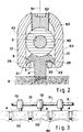
- the device for immobilizing a bar for osteosynthesis or arthrodesis described above is used in the following manner, described in the case of a spinal arthrodesis schematically represented, FIG. 3, on a vertebral column 60.
- the surgeon begins by placing several rods 4 in the vertebrae 70 by screwing them until their limit sinking defined, for example, by a stop on each rod 4.
- On the bar 2 he puts on as many connecting elements 40 as 'there are heads 5 which emerge from the vertebrae 70 and give the bar the desired shape so that it passes through all the heads 5 and so that the connecting elements 40 can rest in the housings 53 provided for this purpose on their face 6.
- the bar and the connecting elements are then in the position shown on the left-hand side of FIG. 1.
- the surgeon then takes as many jumpers 10 as there are visible heads and places them in cooperation with these heads, as described below. after.
- Each rider is slid over the bar, for example in the space 71 between two heads, so that its two lateral branches frame the bar "on horseback", the latter being positioned in the hollow 23 of the "U” and advantageously pressed against the bottom 27.
- This first movement of each jumper is illustrated by the right-hand portion in dashed lines 61 in FIG. 1. From this position, the jumper is translated along the path illustrated, in FIG. 1, by the right portion in broken lines 62, until the projecting portions 25, 26 engage in the groove 30 of the head with which this rider must be associated.
- the surgeon can then place the nut 52 by screwing it into the threaded orifice 50, until its end 63 comes into contact with the connecting element 40 and presses strongly on it so that, by reaction, it s 'exerts a couple of forces between the rider and the head capable of holding the rider 10, the head 5 and the bar 2 perfectly integral by the connecting element 40.
Abstract
Description
La présente invention concerne les dispositifs d'immobilisation d'une barre par rapport à une partie osseuse en vue, par exemple, de réaliser une ostéosynthèse ou une arthrodèse, notamment rachidienne, c'est-à-dire les dispositifs qui permettent, au moyen d'au moins une barre et de moyens de fixation, de réaliser une liaison entre deux os tels que, par exemple, deux vertèbres d'une colonne vertébrale.The present invention relates to devices for immobilizing a bar relative to a bone part with a view, for example, to carrying out an osteosynthesis or an arthrodesis, in particular spinal, that is to say the devices which allow, by means at least one bar and fixing means, to make a connection between two bones such as, for example, two vertebrae of a spine.
On connaît déjà différents types de dispositifs pour arthrodese rachidienne qui sont généralement constitués d'un ensemble de fixations aptes à être implantées dans les os à réunir et d'au moins une barre couplée solidairement à cet ensemble de fixations.There are already known different types of devices for spinal arthrodesis which generally consist of a set of fasteners capable of being implanted in the bones to be joined and of at least one bar coupled integrally to this set of fasteners.
Un tel dispositif est par exemple décrit dans le Brevet DE-A-4 107 480. II comporte essentiellement une tige et une tête à deux faces opposées, un cavalier en forme sensiblement de "U" comprenant au moins une base et deux branches latérales solidaires de la base en l'une de leurs extrémités, deux crochets montés respectivement sur l'extrémité libre des deux branches latérales, latéralement à ces branches, vers l'intérieur du "U" et sensiblement en regard l'un de l'autre, et des moyens pour exercer un couple de forces opposées entre le cavalier et la tête par l'intermédiaire de la barre de façon à solidariser ensemble le cavalier, la tête et la barre.Such a device is for example described in Patent DE-A-4,107,480. It essentially comprises a rod and a head with two opposite faces, a rider in the shape of a substantially "U" comprising at least one base and two integral lateral branches from the base at one of their ends, two hooks mounted respectively on the free end of the two lateral branches, laterally to these branches, towards the inside of the "U" and substantially facing one another, and means for exerting a couple of opposite forces between the rider and the head via the bar so as to join together the rider, the head and the bar.
Ce dispositif connu permet de fixer une barre pour obtenir une arthrodèse rachidienne, mais présente l'inconvénient de rendre parfois très difficile l'alignement de la barre de liaison par rapport aux vertèbres.This known device makes it possible to fix a bar to obtain a spinal arthrodesis, but has the disadvantage of making it very difficult sometimes to align the connecting bar with respect to the vertebrae.
La présente invention a ainsi pour but de réaliser un dispositif d'immobilisation d'une barre par rapport à une partie osseuse en vue, par exemple, de réaliser une ostéosynthèse ou une arthrodèse, notamment rachidienne, qui obvie aux inconvénients mentionnés ci-dessus.The present invention thus aims to achieve a device for immobilizing a bar relative to a bone part in order, for example, to perform an osteosynthesis or arthrodesis, in particular spinal, which obviates the drawbacks mentioned above.
Plus précisément, la présente invention a pour objet un dispositif d'immobilisation d'une barre par rapport à une partie osseuse en vue, par exemple, de réaliser une ostéosynthèse ou une arthrodèse, notamment rachidienne, comportant des moyens de fixation, ces moyens comportant une tige et une tête à deux faces sensiblement opposées, ladite tige étant solidaire de l'une des deux faces de ladite tête et apte à être liée directement ou indirectement à ladite partie osseuse, un cavalier en forme sensiblement de "U" comprenant au moins une base et deux branches latérales solidaires de ladite base, deux crochets montés respectivement sur l'extrémité libre des deux branches latérales, lesdits crochets étant montés latéralement aux extrémités libres des deux dites branches, vers l'intérieur dudit "U" et sensiblement en regard l'un de l'autre, et des moyens pour exercer un couple de forces opposées entre ledit cavalier et ladite tête par l'intermédiaire de ladite barre de façon à solidariser ensemble ledit cavalier, ladite tête et ladite barre,
caractérisé par le fait que la distance séparant les deux dits crochets est inférieure à la largeur d'au moins une partie de ladite tête et supérieure à la section de ladite tige et de ladite barre, la distance séparant intérieurement les deux dites branches latérales et la profondeur dudit "U" étant supérieures à la section de ladite barre.More specifically, the subject of the present invention is a device for immobilizing a bar with respect to a bone part with a view, for example, to carrying out an osteosynthesis or an arthrodesis, in particular spinal, comprising fixing means, these means comprising a rod and a head with two substantially opposite faces, said rod being integral with one of the two faces of said head and capable of being linked directly or indirectly to said bone part, a rider in the shape of a substantially "U" comprising at least a base and two lateral branches integral with said base, two hooks mounted respectively on the free end of the two lateral branches, said hooks being mounted laterally at the free ends of the two said branches, towards the inside of said "U" and substantially in looking at each other, and means for exerting a couple of opposite forces between said rider and said head by means of said bar so as to join together said rider, said head and said bar,
characterized by the fact that the distance separating the two said hooks is less than the width of at least part of said head and greater than the section of said rod and said bar, the distance internally separating the two said lateral branches and the depth of said "U" being greater than the section of said bar.
D'autres caractéristiques et avantages de la présente invention apparaîtront au cours de la description suivante donnée en regard des dessins annexés à titre illustratif, mais nullement limitatif, dans lesquels:
- la figure 1 représente une vue en perspective éclatée d'un mode de realisation du dispositif selon l'invention pour immobiliser une barre pour ostéosynthèse ou arthrodèse, notamment rachidienne.
- La figure 2 représente une coupe schématique du mode de réalisation selon la figure 1, mais avec tous les éléments constitutifs du dispositif assemblés,
- La figure 3 représente un schéma permettant d'expliciter l'utilisation et les avantages du dispositif selon l'invention, et
- La figure 4 représente, en coupe et en transparence, un autre mode de réalisation d'une partie du dispositif selon l'invention.
- FIG. 1 represents an exploded perspective view of an embodiment of the device according to the invention for immobilizing a bar for osteosynthesis or arthrodesis, in particular the spinal column.
- FIG. 2 represents a schematic section of the embodiment according to FIG. 1, but with all the constituent elements of the device assembled,
- FIG. 3 represents a diagram making it possible to explain the use and the advantages of the device according to the invention, and
- FIG. 4 shows, in section and in transparency, another embodiment of a part of the device according to the invention.
Les figures 1 et 2 représentent un mode de réalisation d'un dispositif 1 pour immobiliser une barre 2 pour, notamment, ostéosynthèse ou arthrodèse rachidienne. Ce dispositif comporte des moyens de fixation 3 sur une partie osseuse 8, ces moyens comprenant une tige 4 et une tête 5 à deux faces 6, 7 sensiblement opposées, la section de la tête étant supérieure à la section de la tige, la tige 4 est solidaire de l'une 7 des deux faces de la tête et elle est apte à être liée directement ou indirectement à la partie osseuse 8, par exemple par vissage quand elle est filetée ou par tout autre moyen adapté. Le dispositif comporte en outre des moyens 9 pour solidariser la barre 2 avec la tête 5.Figures 1 and 2 show an embodiment of a
Ces moyens 9 pour solidariser la barre 2 avec la tête 5 comprennent un cavalier 10 en forme sensiblement de "U" comprenant au moins une base 11 et au moins deux branches latérales 12, 13 solidaires de cette base 11, des moyens d'accrochage 14 de l'extrémité libre 15, 16 des deux branches latérales 12, 13 du cavalier 10 non solidaire de la base 11, avec la tête 5, et des moyens 17 pour exercer un couple de forces opposées entre le cavalier 10 et la tête 5 par l'intermédiaire de la barre 2 de façon à solidariser ensemble le cavalier 10, la tête 5 et la barre 2.These means 9 for securing the
Dans un mode de réalisation avantageux, les moyens d'accrochage 14 de l'extrémité libre 15, 16 des deux branches latérales 12, 13 du cavalier 10 non solidaire de la base 11, avec la tête 5, comportent deux crochets 21, 22 montés respectivement sur l'extrémité libre 15, 16 des deux branches latérales 12, 13. Ces crochets 21, 22 sont montés latéralement aux extrémités libres 15, 16 vers l'intérieur 23 du "U" et sensiblement en regard l'un de l'autre, la distance les séparant étant inférieure à la largeur d'au moins une partie de la tête 5 et supérieure à la section de la tige 4 et de la barre 2, la distance séparant intérieurement les deux branches latérales 12, 13 et la profondeur 23 du "U" étant supérieures à la section de la barre 2, cette section étant constituée par le diamètre de la barre dans le cas le plus avantageux où cette barre est cylindrique de révolution.In an advantageous embodiment, the hooking means 14 of the
De plus, pour que la tête 5 puisse être introduite entre les deux branches du cavalier avant d'être solidarisée avec leur extrémité libre et pour que le cavalier 10 et la tête 5 puissent au moins légèrement pivoter l'un par rapport à l'autre sensiblement autour de l'axe de la tige 4, au moins une partie de la tête, sinon la totalité, a une largeur, prise suivant une direction perpendiculaire à l'axe de la tige 4, inférieure à la distance séparant intérieurement les deux branches latérales du cavalier.In addition, so that the
Avantageusement, les moyens d'accrochage 14 de l'extrémité libre 15, 16 des deux branches latérales 12, 13 du cavalier 10, avec la tête 5, comportent en outre une partie en saillie 25, 26 sur chacun des crochets 21, 22, ces parties 25, 26 formant saillie vers le fond 27 du "U". Dans ce cas, pour obtenir une bonne association des crochets avec la tête 5, cette tête comporte avantageusement une rainure en creux 30 réalisée sur sa face 7 solidaire de la tige 4 et d'une section sensiblement complémentaire de celle des parties en saillie 25, 26.Advantageously, the hooking means 14 of the
Dans une réalisation avantageuse, cette rainure 30 et les parties en saillie 25, 26 sont définies sur deux lignes sensiblement circulaires de même rayon, comme représenté sur la figure 4, de façon à obtenir un engagement parfait des parties en saillie 25, 26 dans la rainure 30 quelles que soient les positions angulaires relatives de la tête 5 et du cavalier 10.In an advantageous embodiment, this
De plus, comme cela apparaît sur la figure 2, la section de la rainure 30 et des parties en saillie 25, 26 est avantageusement triangulaire ou d'une forme pouvant être assimilée à une forme triangulaire ou analogue, pour obtenir un engagement du type conique et favoriser un couplage solide et rigide entre la tête 5 et le cavalier 10.In addition, as shown in Figure 2, the section of the
Il est précisé que l'exemple du cavalier 10 illustré notamment sur la figure 1 est une réalisarion préférentielle pour la plupart des cas d'utilisation du dispositif. Cependant, sans pour autant perdre sa forme sensiblement en "U", le cavalier peut être réalisé de façon que ses deux branches latérales 12, 13 soient reliées entre elles sur l'une des deux faces du "U" par une paroi à proximité des extrémités 15, 16 non solidaires de la base 11. 11 est seulement nécessaire que, dans cette paroi, soit définie une ouverture qui permette le passage de la barre 2 et la translation du cavalier 10 suivant son axe 51 pour que les moyens d'accrochage 14 puissent coopérer avec la tête 5.It is specified that the example of the
Dans un mode de réalisation préférentiel, comme illustré sur les figures 1 et 2, les moyens 17 pour exercer un couple de forces opposées entre le cavalier 10 et la tête 5 par l'intermédiaire de la barre 2 de façon à solidariser ensemble le cavalier 10, la tête 5 et la barre 2 comportent un élément de liaison 40 entourant au moins partiellement la barre 2 et avantageusement déformable. Lorsque les différents éléments constitutifs du dispositif sont assemblés, cet élément de liaison 40 est situé entre les deux branches latérales 12, 13 du cavalier 10 et repose sur la face 6 de la tête 5 opposée à la face 7 solidaire de la tige 4. De préférence, cet élément de liaison 40 affecte, par sa surface extérieure 41, une forme sensiblement sphérique d'un diamètre légèrement inférieur à la distance séparant intérieurement les deux branches latérales 12, 13 et comporte une percée diamétrale 42 d'une section sensiblement égale ou légèrement supérieure à la section de la barre 2. il peut être constitué, par exemple, par une olive fendue et/ou réalisée en un matériau élastique.In a preferred embodiment, as illustrated in FIGS. 1 and 2, the
Pour favoriser le centrage de la barre 2 par rapport aux deux branches latérales 12, 13, la face 6 de la tête opposée à la face 7 solidaire de la tige 4 comporte un logement en creux 53 complémentaire d'au moins une portion de la surface extérieure 41 sensiblement sphérique de l'élément de liaison 40.To promote the centering of the
Les moyens 14 pour exercer un couple de forces opposées entre le cavalier 10 et la tête 5 par l'intermédiaire de la barre 2 comportent en outre, par exemple comme illustré, un orifice taraudé 50 traversant la base 11 du cavalier 10 suivant un axe 51 sensiblement parallèle aux deux branches latérales 12, 13 et un écrou fileté 52 au même pas que l'orifice taraudé 50, l'écrou étant apte à être vissé dans cet orifice 50 de façon à venir en direction de la barre 2 quand elle est placée entre les deux branches 12, 13 du cavalier et à venir au contact de l'élément de liaison 40.The
Quand l'élément de liaison 40 est sphérique, la face 63 de l'écrou 52 qui vient à son contact est concave sphérique, complémentaire de la surface extérieure de l'élément 40, pour que la force pressante exercée par l'écrou 52 sur l'élément de liaison soit parfaitement répartie sur une surface la plus grande possible.When the connecting
Il est précisé que la tige 4 peut être une tige filetée apte à se placer directement par vissage dans une partie d'os, mais qu'elle peut être aussi une tige de liaison indirecte entre deux parties osseuses au moyen, par exemple, de deux barres qui sont elles-mêmes fixées à ces parties osseuses par tous moyens, notamment par des dispositifs selon l'invention.It is specified that the
De même, le cavalier peut ne comporter qu'une base et deux branches latérales 12, 13 pour immobiliser une barre 2. Mais il peut aussi comporter, sur une même base 11, trois branches permettant de définir deux "U" juxtaposés, par exemple pour immobiliser ensemble deux barres 2.Similarly, the rider may have only one base and two
Le dispositif d'immobilisation d'une barre pour ostéosynthèse ou arthrodèse décrit ci-dessus s'utilise de la façon suivante décrite dans le cas d'une arthrodèse rachidienne schématiquement représentée, figure 3, sur une colonne vertébrale 60.The device for immobilizing a bar for osteosynthesis or arthrodesis described above is used in the following manner, described in the case of a spinal arthrodesis schematically represented, FIG. 3, on a
Le chirurgien commence par placer plusieurs tiges 4 dans les vertèbres 70 en les vissant jusqu'à obtenir leur enfoncement limite défini, par exemple, par une butée sur chaque tige 4. Sur la barre 2, il enfile autant d'éléments de liaison 40 qu'il y a de têtes 5 qui emergent des vertèbres 70 et donne à la barre la forme voulue pour qu'elle passe par toutes les têtes 5 et que les éléments de liaison 40 puissent reposer dans les logements 53 prévus à cet effet sur leur face 6. La barre et les éléments de liaison se trouvent alors dans la position représentée sur la partie gauche de la figure 1. Le chirurgien prend ensuite autant de cavaliers 10 que de têtes apparentes et les place en coopération avec ces têtes, comme décrit ci-après.The surgeon begins by placing
Chaque cavalier est glissé sur la barre, par exemple dans l'espace 71 compris entre deux têtes, de façon que ses deux branches latérales encadrent "à cheval" la barre, celle-ci se trouvant positionnée dans le creux 23 du "U" et avantageusement plaquée contre le fond 27. Ce premier mouvement de chaque cavalier est illustré par la portion de droite en traits interrompus 61 sur la figure 1. A partir de cette position, le cavalier est translaté suivant le trajet illustré, sur la figure 1, par la portion de droite en traits interrompus 62, jusqu'à ce que les parties en saillie 25, 26 viennent s'engager dans la rainure 30 de la tête à laquelle ce cavalier doit être associé. De par la forme de la section de ces parties en saillie et de la rainure, les parties en saillie viennent s'enficher en force dans la rainure par un coincement dit conique, et ce, quelle que soit la position angulaire de la tête puisque, comme décrit ci-avant, cette rainure 30 et les parties en saillie 25, 26 sont circulaires de même rayon.Each rider is slid over the bar, for example in the
Le chirurgien peut alors placer l'écrou 52 en le vissant dans l'orifice taraudé 50, jusqu'à ce que son extrémité 63 vienne au contact de l'élément de liaison 40 et appuie fortement sur lui pour que, par réaction, il s'exerce un couple de forces entre le cavalier et la tête capable de maintenir parfaitement solidaires le cavalier 10, la tête 5 et la barre 2 par l'intermédiaire de l'élément de liaison 40.The surgeon can then place the
A la description ci-dessus du mode d'assemblage des éléments constitutifs du dispositif d'immobilisation d'une barre pour ostéosynthèse ou arthrodèse selon l'invention, il est évident que ce dispositif évite tous les inconvénients mentionnés au préambule tout en conservant les avantages des dispositifs de l'art antérieur.In the above description of the method of assembling the constituent elements of the device for immobilizing a bar for osteosynthesis or arthrodesis according to the invention, it is obvious that this device avoids all the drawbacks mentioned in the preamble while retaining the advantages devices of the prior art.
Claims (12)
Applications Claiming Priority (2)
| Application Number | Priority Date | Filing Date | Title |
|---|---|---|---|
| FR9212312 | 1992-10-07 | ||
| FR9212312A FR2696335B1 (en) | 1992-10-07 | 1992-10-07 | Device for immobilizing a bar for, in particular, osteosynthesis or arthrodesis. |
Publications (1)
| Publication Number | Publication Date |
|---|---|
| EP0592266A1 true EP0592266A1 (en) | 1994-04-13 |
Family
ID=9434548
Family Applications (1)
| Application Number | Title | Priority Date | Filing Date |
|---|---|---|---|
| EP93402297A Ceased EP0592266A1 (en) | 1992-10-07 | 1993-09-21 | Rod locking device, especially for osteosynthesis or arthrodesis |
Country Status (2)
| Country | Link |
|---|---|
| EP (1) | EP0592266A1 (en) |
| FR (1) | FR2696335B1 (en) |
Cited By (9)
| Publication number | Priority date | Publication date | Assignee | Title |
|---|---|---|---|---|
| WO2006096306A2 (en) | 2005-03-04 | 2006-09-14 | Depuy Spine Sarl | Constrained motion bone screw assembly |
| US7951175B2 (en) | 2005-03-04 | 2011-05-31 | Depuy Spine, Inc. | Instruments and methods for manipulating a vertebra |
| US7951174B2 (en) | 2005-10-21 | 2011-05-31 | Depuy Spine, Inc. | Adjustable bone screw assembly |
| US8348952B2 (en) | 2006-01-26 | 2013-01-08 | Depuy International Ltd. | System and method for cooling a spinal correction device comprising a shape memory material for corrective spinal surgery |
| US8608746B2 (en) | 2008-03-10 | 2013-12-17 | DePuy Synthes Products, LLC | Derotation instrument with reduction functionality |
| US8709015B2 (en) | 2008-03-10 | 2014-04-29 | DePuy Synthes Products, LLC | Bilateral vertebral body derotation system |
| CN104799931A (en) * | 2015-04-13 | 2015-07-29 | 李贵涛 | Glenoid rail chain type returning fixing and dynamic pedicle screw system |
| US9101416B2 (en) | 2003-01-24 | 2015-08-11 | DePuy Synthes Products, Inc. | Spinal rod approximator |
| US10973556B2 (en) | 2008-06-17 | 2021-04-13 | DePuy Synthes Products, Inc. | Adjustable implant assembly |
Citations (7)
| Publication number | Priority date | Publication date | Assignee | Title |
|---|---|---|---|---|
| US4805602A (en) * | 1986-11-03 | 1989-02-21 | Danninger Medical Technology | Transpedicular screw and rod system |
| EP0330881A1 (en) * | 1988-03-02 | 1989-09-06 | Synthes Ag Chur | Open backed pedicle screw |
| EP0436885A2 (en) * | 1989-12-21 | 1991-07-17 | Anton Prof. Dr. Härle | Auxiliary osteosynthesis screw |
| EP0441729A1 (en) * | 1990-02-08 | 1991-08-14 | STRYKER CORPORATION (a Michigan corporation) | Swivelling fastening device for spinal osteosynthesis rods |
| US5085660A (en) * | 1990-11-19 | 1992-02-04 | Lin Kwan C | Innovative locking plate system |
| EP0487895A1 (en) * | 1990-11-26 | 1992-06-03 | Synthes AG, Chur | Anchoring device |
| DE4107480A1 (en) * | 1991-03-08 | 1992-09-10 | Heinrich Ulrich | Screw for fixing appliance for correcting spinal column - has specially shaped head to receive appliance rod |
Family Cites Families (1)
| Publication number | Priority date | Publication date | Assignee | Title |
|---|---|---|---|---|
| DE3800052A1 (en) * | 1987-07-08 | 1989-07-13 | Harms Juergen | POSITIONING SCREW |
-
1992
- 1992-10-07 FR FR9212312A patent/FR2696335B1/en not_active Expired - Fee Related
-
1993
- 1993-09-21 EP EP93402297A patent/EP0592266A1/en not_active Ceased
Patent Citations (7)
| Publication number | Priority date | Publication date | Assignee | Title |
|---|---|---|---|---|
| US4805602A (en) * | 1986-11-03 | 1989-02-21 | Danninger Medical Technology | Transpedicular screw and rod system |
| EP0330881A1 (en) * | 1988-03-02 | 1989-09-06 | Synthes Ag Chur | Open backed pedicle screw |
| EP0436885A2 (en) * | 1989-12-21 | 1991-07-17 | Anton Prof. Dr. Härle | Auxiliary osteosynthesis screw |
| EP0441729A1 (en) * | 1990-02-08 | 1991-08-14 | STRYKER CORPORATION (a Michigan corporation) | Swivelling fastening device for spinal osteosynthesis rods |
| US5085660A (en) * | 1990-11-19 | 1992-02-04 | Lin Kwan C | Innovative locking plate system |
| EP0487895A1 (en) * | 1990-11-26 | 1992-06-03 | Synthes AG, Chur | Anchoring device |
| DE4107480A1 (en) * | 1991-03-08 | 1992-09-10 | Heinrich Ulrich | Screw for fixing appliance for correcting spinal column - has specially shaped head to receive appliance rod |
Cited By (25)
| Publication number | Priority date | Publication date | Assignee | Title |
|---|---|---|---|---|
| US9101416B2 (en) | 2003-01-24 | 2015-08-11 | DePuy Synthes Products, Inc. | Spinal rod approximator |
| US9795416B2 (en) | 2005-03-04 | 2017-10-24 | Medos International Sárl | Constrained motion bone screw assembly |
| US11000315B2 (en) | 2005-03-04 | 2021-05-11 | Medos International Sarl | Constrained motion bone screw assembly |
| US7951172B2 (en) | 2005-03-04 | 2011-05-31 | Depuy Spine Sarl | Constrained motion bone screw assembly |
| US7951175B2 (en) | 2005-03-04 | 2011-05-31 | Depuy Spine, Inc. | Instruments and methods for manipulating a vertebra |
| US8709044B2 (en) | 2005-03-04 | 2014-04-29 | DePuy Synthes Products, LLC | Instruments and methods for manipulating vertebra |
| US7951168B2 (en) | 2005-03-04 | 2011-05-31 | Depuy Spine, Inc. | Instruments and methods for manipulating vertebra |
| US8007516B2 (en) | 2005-03-04 | 2011-08-30 | Depuy Spine, Inc. | Instruments and methods for manipulating vertebra |
| US11446066B2 (en) | 2005-03-04 | 2022-09-20 | DePuy Synthes Products, Inc. | Instruments and methods for manipulating vertebra |
| US10314624B2 (en) | 2005-03-04 | 2019-06-11 | DePuy Synthes Products, Inc. | Instruments and methods for manipulating vertebra |
| US10172648B2 (en) | 2005-03-04 | 2019-01-08 | Medos International Sarl | Constrained motion bone screw assembly |
| US11849978B2 (en) | 2005-03-04 | 2023-12-26 | Medos International Sarl | Constrained motion bone screw assembly |
| EP1853200A4 (en) * | 2005-03-04 | 2010-05-12 | Depuy Spine Sarl | Constrained motion bone screw assembly |
| US9095379B2 (en) | 2005-03-04 | 2015-08-04 | Medos International Sarl | Constrained motion bone screw assembly |
| WO2006096306A2 (en) | 2005-03-04 | 2006-09-14 | Depuy Spine Sarl | Constrained motion bone screw assembly |
| EP1853200A2 (en) * | 2005-03-04 | 2007-11-14 | DePuy Spine Sàrl | Constrained motion bone screw assembly |
| US8845700B2 (en) | 2005-10-21 | 2014-09-30 | DePuy Synthes Products, LLC. | Adjustable bone screw assembly |
| US8603144B2 (en) | 2005-10-21 | 2013-12-10 | DePuy Synthes Products, LLC | Adjustable bone screw assembly |
| US7951174B2 (en) | 2005-10-21 | 2011-05-31 | Depuy Spine, Inc. | Adjustable bone screw assembly |
| US8348952B2 (en) | 2006-01-26 | 2013-01-08 | Depuy International Ltd. | System and method for cooling a spinal correction device comprising a shape memory material for corrective spinal surgery |
| US9326798B2 (en) | 2008-03-10 | 2016-05-03 | DePuy Synthes Products, Inc. | Derotation instrument with reduction functionality |
| US8608746B2 (en) | 2008-03-10 | 2013-12-17 | DePuy Synthes Products, LLC | Derotation instrument with reduction functionality |
| US8709015B2 (en) | 2008-03-10 | 2014-04-29 | DePuy Synthes Products, LLC | Bilateral vertebral body derotation system |
| US10973556B2 (en) | 2008-06-17 | 2021-04-13 | DePuy Synthes Products, Inc. | Adjustable implant assembly |
| CN104799931A (en) * | 2015-04-13 | 2015-07-29 | 李贵涛 | Glenoid rail chain type returning fixing and dynamic pedicle screw system |
Also Published As
| Publication number | Publication date |
|---|---|
| FR2696335A1 (en) | 1994-04-08 |
| FR2696335B1 (en) | 1994-12-02 |
Similar Documents
| Publication | Publication Date | Title |
|---|---|---|
| EP2440144B1 (en) | Device for protecting adjacent levels of a spinal segment | |
| EP0802772B1 (en) | Spinal fixator | |
| EP1339337B1 (en) | Device for fixing a rod and a spherical symmetry screw head | |
| EP1467666B1 (en) | Connector for vertebral anchoring system | |
| EP1926444A1 (en) | Vertebral fixing system | |
| FR2780269A1 (en) | Spinal implant for use with linking rod to treat fractures and correct deformities | |
| EP0756472A1 (en) | Device for stabilizing orthopedic anchors | |
| CH678485A5 (en) | ||
| FR2683446A1 (en) | MODULAR EXTERNAL FIXER FOR IMMOBILIZING A FRACTURE FIREPLACE. | |
| FR2804314A1 (en) | INTERVERTEBRAL CONNECTION DEVICE WITH CONNECTION BAR FOR FIXING A CONNECTING ROD | |
| CA2377028A1 (en) | Anchoring system with safety ring | |
| FR2761256A1 (en) | RACHIDIAN OSTEOSYNTHESIS INSTRUMENTATION WITH CONNECTING CONNECTOR BETWEEN A VERTEBRAL ROD AND BONE ANCHORING ORGANS | |
| FR2659225A1 (en) | Transverse fixation device for ensuring a rigid transverse connection between two rods of a spinal osteosynthesis system | |
| WO2003026521A1 (en) | Vertebral fixing device | |
| FR2499400A1 (en) | Fixing device for compound fracture - comprises planar element with depressions receiving spherical joints to support bone fixing pins | |
| EP0592266A1 (en) | Rod locking device, especially for osteosynthesis or arthrodesis | |
| FR2795622A1 (en) | CONNECTOR FOR OSTEOSYNTHESIS SYSTEM FOR PROVIDING RIGID BOND BETWEEN TWO RODS OF SPINAL OSTEOSYNTHESIS SYSTEM, OSTEOSYNTHESIS SYSTEM USING SUCH CONNECTOR | |
| FR2777449A1 (en) | Ligament tensioning instrument for use in a spine stabilizing system | |
| FR2665353A1 (en) | External fixator for reducing fractures of the wrist | |
| FR2682280A1 (en) | Fixation device for spinal osteosynthesis rod | |
| FR2722394A1 (en) | SPINAL OSTEOSYNTHESIS DEVICE | |
| FR2810873A1 (en) | Intervertebral coupling for two or more vertebrae has intermediate element between fixed and mobile components to allow movement | |
| FR2758971A1 (en) | Intervertebral connection surgical insert | |
| FR2730155A1 (en) | Connection between screw and shaft in osteosynthesis implant | |
| FR2806902A1 (en) | Bone retaining assembly, esp for two vertebrae, has connecting bar, pedicular screw and coupling block |
Legal Events
| Date | Code | Title | Description |
|---|---|---|---|
| PUAI | Public reference made under article 153(3) epc to a published international application that has entered the european phase |
Free format text: ORIGINAL CODE: 0009012 |
|
| AK | Designated contracting states |
Kind code of ref document: A1 Designated state(s): CH DE ES FR GB IT LI |
|
| 17P | Request for examination filed |
Effective date: 19941007 |
|
| 17Q | First examination report despatched |
Effective date: 19961212 |
|
| STAA | Information on the status of an ep patent application or granted ep patent |
Free format text: STATUS: THE APPLICATION HAS BEEN REFUSED |
|
| 18R | Application refused |
Effective date: 20001102 |