EP0591927B1 - Conduit d'alimentation dentaire transparent - Google Patents
Conduit d'alimentation dentaire transparent Download PDFInfo
- Publication number
- EP0591927B1 EP0591927B1 EP93116080A EP93116080A EP0591927B1 EP 0591927 B1 EP0591927 B1 EP 0591927B1 EP 93116080 A EP93116080 A EP 93116080A EP 93116080 A EP93116080 A EP 93116080A EP 0591927 B1 EP0591927 B1 EP 0591927B1
- Authority
- EP
- European Patent Office
- Prior art keywords
- transparent
- supply passage
- tube
- tube unit
- check valve
- Prior art date
- Legal status (The legal status is an assumption and is not a legal conclusion. Google has not performed a legal analysis and makes no representation as to the accuracy of the status listed.)
- Expired - Lifetime
Links
Images

Classifications
-
- A—HUMAN NECESSITIES
- A61—MEDICAL OR VETERINARY SCIENCE; HYGIENE
- A61C—DENTISTRY; APPARATUS OR METHODS FOR ORAL OR DENTAL HYGIENE
- A61C1/00—Dental machines for boring or cutting ; General features of dental machines or apparatus, e.g. hand-piece design
- A61C1/0007—Control devices or systems
- A61C1/0038—Pneumatic systems
Definitions
- This invention relates to a transparent dental tube unit and, more particularly, to a transparent dental tube for supplying a fluid under pressure, such as water or air, to the foremost part of a main body of a dental handpiece.
- a dental tube unit employed for dental treatment is made up of a dental handpiece, a fluid supply source for supplying the fluid, such as water or air, under pressure, and a tube unit used as passages for air or water from the supply source to the handpiece.
- the tube unit includes an air supply tube, an air discharge tube, a water supply tube for supplying water to the foremost part of the handpiece, and an outer enclosure tube enclosing therein the air supply tube, the air discharge tube and the water supply tube.
- the air supplied under pressure from the fluid supply source through the air supply tube to the main body of the handpiece is used for running a turbine mechanism disposed at a head part of the handpiece in rotation so as to be then discharged via the air discharge tube.
- the water supply tube is used for supplying water from the supply source to the dental handpiece or for cooling the teeth which have become hot under the heat of friction generated during the dental treatment. It is noted that there are occasions wherein the air is discharged without passing through the air discharge tube.
- Document EP-A-0 393 364 reveals a dental handpiece containing a turbine gas supply passage for guiding a pressurized gas from a pressurized fluid supply source to a dental handpiece for driving a turbine provided in said handpiece, a liquid supply passage for allowing a pressurized liquid from said pressurized fluid source to be passed to said dental handpiece for dissipating heat generated by friction and an enclosure tube for enclosing such turbine gas supply passage and said liquid supply passage therein.
- this dental handpiece does not solve the problem, that it is necessary to check the status of contamination within the tube from time to time.
- a transparent dental tube unit as defined in claim 1.
- Fig.1 is a schematic overall side view showing transparent tubes for a dental unit according to the present invention, with the tube being shown partially in section.
- Fig.2 is a perspective view cut along line 2-2 in Fig.1, with the inside of the tubes being partially seen from outside.
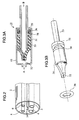
- Fig. 3A is a cross-sectional view showing a check valve of Fig. 1 in detail.
- Fig. 3B is an exploded perspective view showing the check valve shown in Fig. 3A.
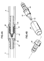
- Fig. 4A is a cross-sectional view showing another check valve mounted halfway in a transparent water supply tube in detail.
- Fig. 4B is an exploded perspective view showing the check valve shown in Fig. 4A.
- Fig. 1 schematically illustrates, in an overall view, a transparent tube unit 1 according to the present invention, with a part of the tube being shown in cross-section.
- the transparent tube unit 1 is made up of an air supply tube 3, an air discharge tube 4, shown in Fig. 2, a water supply tube 5, a chip air tube 6, an outer enclosure tube 2 enclosing the tubes 3 to 6 and lead wires 14 shown in Fig. 2, tube fixing metal fixtures 8, 9 for securing the tubes 3 to 6 within the outer enclosure tube 2 against distortion at the front and rear ends of the outer enclosure tube 2, and a connector ring 7 connected to the tube fixing metal fixture 8 and to the main body of the dental handpiece, as explained in more detail hereinbelow.
- the outer enclosure tube 2 is fitted into a space between the metal fixtures 8 and a volute joint 10 on the outer periphery thereof, while the air supply tube 3, the air discharge tube 4, the water supply tube 5 and the chip air tube 6 are supported within the outer enclosure tube 2 at a constant distance from one another.
- Fig. 1 shows a transparent dental tube unit according to the present invention, in which a check valve 11 is enclosed within the air supply tube 3 at the foremost part thereof.
- a protrusion 15 in the form of an attachment plug and a receptacle-shaped recess 16 provided on the side of the connector ring 7 are detachably connected to each other.
- Fig 2 shows the transparent dental tube unit 1 in a perspective view looking in the direction of line 2-2 in Fig. 1.
- the main components of the tube unit 1 include the air supply tube 3, the air discharge tube 4, the air supply tube 5, the chip air tube 6 and the outer enclosure tube 2 enclosing these tubes 3 to 6.
- the air supply tube 3 is a passage for air supplied from a pressurized gas supply source, not shown, for running the turbine of the dental handpiece in rotation
- the air discharge tube 4 is a passage for the air which has been used for running the turbine in rotation and which is to be discharged to outside after passage through the air discharge tube.
- the water supply tube 5 guides water from its supply source, not shown, to the handpiece so that the water may be used for dissipating the heat generated under friction between the teeth and the dental tool.
- the chip air tube 6 is a passage for intermittently supplying the air for scattering the tooth debris.
- the tubes enclosed in the outer enclosure tube 2 are not limited to the air supply tube 3, the air discharge tube 4, the water supply tube 5 or the chip air tube 6 used in the present embodiment, since a variety of dental handpieces are presently available and the present invention may be adapted for use with these existing handpieces.
- These tubes are formed of a material having high safety and superior transparency and resistance against chemicals.
- the material include fluororesin elastomers composed of a fluororesin, e.g. ethylene tetrafluoroethylene (ETFE) and a fluororubber, e.g. fluorinated vinylidene fluoride - hexafluoropropylene -tetrafluoroethylene.
- a fluororesin e.g. ethylene tetrafluoroethylene (ETFE)
- a fluororubber e.g. fluorinated vinylidene fluoride - hexafluoropropylene -tetrafluoroethylene.
- An opening 32 is formed at the foremost part of the valve member 31.
- the opening 32 remains closed under elasticity of the valve member 31 as shown.
- the opening 32 is opened against the elasticity of the valve member 31 to permit air to pass therethrough in such direction.
- the valve member 31 is secured in position by being fitted over a conduit 33 within the protrusion 15.
- the conduit 33 is formed with flanges 34, 35 between which a rubber ring 36 is fitted to prevent air leakage.
- a check valve similar to the check valve 11 provided in the air supply tube 3 may also be provided in the air discharge tube 4, the water supply tube 5 or the chip air tube 6.
- the check valve 11 is mounted in the opposite direction to that of the check valve 11 provided in the air supply tube 4 so that air may normally be discharged from the handpiece towards the transparent tube unit 1.
- check valves 11 are provided in both the air supply tube 3 and the air discharge tube 4, when impurities are sucked from the foremost part of the handpiece, the air flow is reversed so that both of the check valves are actuated simultaneously to assure complete prevention of suction of impurities.
- Figs.4A and 4B illustrate a modified embodiment in which a valve member 41 similar to the valve member 31 shown in Figs.3A and 3B is provided halfway in the transparent water supply tube 5.
- An opening 42 is formed in the foremost part of the valve member 41 and functions in the same way as the opening 32 described above.
- the valve member 41 is secured in position between a tubular member 43 and a rear fixing tube 44 to the rear part of which the water supply tube 5 is secured.
- a front fixing tube 45 is threadedly attached to the tubular member 43 and the water supply tube 5 is fixedly attached to the foremost part of the front fixing tube 45.
- the tubular member 43 may also be formed of a transparent material, in which case operational troubles of the valve member 41 may be noticed at a glance, so that repair or exchange may be undertaken immediately.
- check valves 11, 40 are provided in one and the same tube, such as the air supply tube 3, contamination due to the flow reversal may be prevented more positively.
Landscapes
- Health & Medical Sciences (AREA)
- Engineering & Computer Science (AREA)
- Water Supply & Treatment (AREA)
- Oral & Maxillofacial Surgery (AREA)
- Dentistry (AREA)
- Epidemiology (AREA)
- Life Sciences & Earth Sciences (AREA)
- Animal Behavior & Ethology (AREA)
- General Health & Medical Sciences (AREA)
- Public Health (AREA)
- Veterinary Medicine (AREA)
- Dental Tools And Instruments Or Auxiliary Dental Instruments (AREA)
Claims (12)
- Unité de conduits dentaires (1) comprenant un passage d'alimentation de gaz de turbine (3) pour permettre à un gaz sous pression fourni par une source d'alimentation de fluide sous pression de passer dans une poignée dentaire pour entraíner une turbine logée à l'intérieur de ladite poignée dentaire, un passage d'alimentation de liquide (5) pour permettre à un liquide sous pression fourni par ladite source de fluide sous pression de passer dans ladite poignée dentaire pour dissiper la chaleur générée par la friction et un conduit-gaine (2) pour loger ledit passage d'alimentation de gaz de turbine (3) et ledit passage d'alimentation de liquide (5),
caractérisée par le fait que ledit passage d'alimentation de gaz de turbine (3), que ledit passage d'alimentation de liquide (5) et que ledit conduit-gaine (2) sont transparents. - Unité de conduits (1) selon la revendication 1 comprenant en outre un passage transparent de décharge de gaz de turbine (4) pour décharger le gaz sous pression de ladite poignée dentaire après que le gaz ait traversé ladite poignée dentaire.
- Unité de conduits (1) selon la revendication 1 ou la revendication 2 comprenant en outre un passage transparent d'alimentation de gaz de dispersion des débris (6) pour permettre à un gaz fourni par ladite source d'alimentation de fluide sous pression de disperser les débris de dent qui risquent de passer dans ladite poignée dentaire.
- Unité de conduits (1) selon la revendication 1 comprenant en outre au moins un clapet de retenue (11, 40) dans ledit passage d'alimentation de gaz de turbine (3), et/ou ledit passage transparent d'alimentation de liquide (5) pour empêcher l'inversion de flux.
- Unité de conduits selon la revendication 2 comprenant en outre au moins un clapet de retenue (11, 40) dans ledit passage de décharge de gaz de turbine (4) pour empêcher l'inversion du flux.
- Unité de conduits (1) selon la revendication 3 comprenant en outre au moins un clapet de retenue (11, 40) dans ledit passage transparent d'alimentation de gaz de dispersion des débris (6) pour empêcher l'inversion du flux.
- Unité de conduits (1) selon la revendication 4 dans lequel ledit clapet de retenue (11) est connecté à un conduit (35) placé à la partie la plus avancée dudit passage transparent d'alimentation de gaz de turbine (3) et/ou ledit passage d'alimentation de liquide (5).
- Unité de conduits (1) selon la revendication 6 dans lequel ledit clapet de retenue (11) est connecté à un conduit (35) placé à une partie la plus avancée dudit passage d'alimentation de gaz de dispersion des copeaux (6).
- Unité de conduits (1) selon la revendication 4 dans laquelle ledit clapet de retenue (40) est placé à mi-chemin dudit passage transparent d'alimentation de gaz de turbine (3) et/ou dudit passage transparent d'alimentation de liquide (5).
- Unité de conduits (1) selon la revendication 5 dans laquelle le clapet de retenue (40) est placé à michemin dans ledit passage transparent de décharge de gaz de turbine (4).
- Unité de conduits (1) selon la revendication 6 dans laquelle ledit clapet de retenue (40) est placé à mi-chemin dans ledit passage d'alimentation de gaz de turbine (6).
- Unité de conduits (1) selon l'une quelconque des revendications 9 à 11 dans laquelle ledit clapet de retenue (40) est constitué par un corps de clapet (41) pour permettre au fluide de le traverser et une enveloppe transparente (43) pour fixer le corps de clapet (41) à l'intérieur de ladite enveloppe.
Applications Claiming Priority (2)
| Application Number | Priority Date | Filing Date | Title |
|---|---|---|---|
| JP70264/92 | 1992-10-08 | ||
| JP1992070264U JPH0722250Y2 (ja) | 1992-10-08 | 1992-10-08 | 歯科用ユニット |
Publications (2)
| Publication Number | Publication Date |
|---|---|
| EP0591927A1 EP0591927A1 (fr) | 1994-04-13 |
| EP0591927B1 true EP0591927B1 (fr) | 1998-01-14 |
Family
ID=13426501
Family Applications (1)
| Application Number | Title | Priority Date | Filing Date |
|---|---|---|---|
| EP93116080A Expired - Lifetime EP0591927B1 (fr) | 1992-10-08 | 1993-10-05 | Conduit d'alimentation dentaire transparent |
Country Status (5)
| Country | Link |
|---|---|
| US (1) | US5407352A (fr) |
| EP (1) | EP0591927B1 (fr) |
| JP (1) | JPH0722250Y2 (fr) |
| AT (1) | ATE162061T1 (fr) |
| DE (1) | DE69316303T2 (fr) |
Families Citing this family (6)
| Publication number | Priority date | Publication date | Assignee | Title |
|---|---|---|---|---|
| WO1996035394A1 (fr) * | 1995-05-12 | 1996-11-14 | Satoh, Hitoshi | Dispositif d'evacuation de fluides buccaux, tube principal et tube de derivation pour ce dernier, dispositif d'alimentation pour ledit tube de derivation |
| DE19529668A1 (de) * | 1995-08-11 | 1997-02-13 | Kaltenbach & Voigt | Ärztliches oder zahnärztliches Turbinen-Handstück |
| US5944520A (en) * | 1996-08-29 | 1999-08-31 | Ash; Albert | Dental hand piece with internal back flow prevention valve |
| US6146137A (en) * | 1998-11-19 | 2000-11-14 | Vogel; William Charles | Contamination prevention device for ultra high speed dental type handpieces |
| ITBO20000713A1 (it) | 2000-12-06 | 2002-06-06 | Castellini Spa | Apparecchiatura e motodo per il rilevamento di biofilm in condotti idrici di riuniti dentali |
| US20030190254A1 (en) * | 2002-04-07 | 2003-10-09 | Frank Falat | Method for ultra-violet disinfecting of compressed air |
Family Cites Families (5)
| Publication number | Priority date | Publication date | Assignee | Title |
|---|---|---|---|---|
| US3077333A (en) * | 1960-05-20 | 1963-02-12 | Dentists Supply Co | High speed tool |
| US3918456A (en) * | 1974-11-19 | 1975-11-11 | Kendall & Co | Catheter unit for cholangiography |
| US5088924A (en) * | 1989-03-01 | 1992-02-18 | Gary Woodward | Dental fiberoptic handpiece hose assembly and method |
| CH679368A5 (fr) * | 1989-04-20 | 1992-02-14 | Bien Air | |
| US5235732A (en) * | 1991-11-12 | 1993-08-17 | Bentley Hal E | Embalming drain tube apparatus |
-
1992
- 1992-10-08 JP JP1992070264U patent/JPH0722250Y2/ja not_active Expired - Lifetime
-
1993
- 1993-10-04 US US08/131,494 patent/US5407352A/en not_active Expired - Lifetime
- 1993-10-05 DE DE69316303T patent/DE69316303T2/de not_active Expired - Fee Related
- 1993-10-05 EP EP93116080A patent/EP0591927B1/fr not_active Expired - Lifetime
- 1993-10-05 AT AT93116080T patent/ATE162061T1/de not_active IP Right Cessation
Also Published As
| Publication number | Publication date |
|---|---|
| ATE162061T1 (de) | 1998-01-15 |
| JPH0631707U (ja) | 1994-04-26 |
| JPH0722250Y2 (ja) | 1995-05-24 |
| US5407352A (en) | 1995-04-18 |
| DE69316303D1 (de) | 1998-02-19 |
| DE69316303T2 (de) | 1998-04-23 |
| EP0591927A1 (fr) | 1994-04-13 |
Similar Documents
| Publication | Publication Date | Title |
|---|---|---|
| JP4447921B2 (ja) | 歯科医療器械のための予防システム及びその使用方法 | |
| US5709545A (en) | Method and apparatus for protecting against cross contamination of patients caused by oral reflux in dental instrument water and air lines | |
| US5501596A (en) | Autoclavable dental scaler handpiece | |
| US4917603A (en) | Dental isolation system | |
| US5204004A (en) | Method and apparatus for preventing bacteriological contamination by a dental tool water line | |
| JP4627986B2 (ja) | 歯科用サンドブラスト具 | |
| US11678962B2 (en) | Lip retractor and suction head for high-volume evacuator | |
| US5944520A (en) | Dental hand piece with internal back flow prevention valve | |
| US5334013A (en) | High speed dental drill with positive pressure air drive | |
| EP0591927B1 (fr) | Conduit d'alimentation dentaire transparent | |
| US5733117A (en) | Sterile fluid delivery system and method | |
| US20160345815A1 (en) | Dental Mirror | |
| US4253831A (en) | Aspirating dental device | |
| US5312251A (en) | Dental implement | |
| US5599184A (en) | Protective system for dental drill units | |
| EP1567047B1 (fr) | Miroir de dentiste | |
| US5156546A (en) | Dental equipment cleaning apparatus and method | |
| JPH04307057A (ja) | 歯科用ハンドピース | |
| CN215019216U (zh) | 一种口腔内局部封闭式诊疗装置 | |
| JPH0698898A (ja) | 歯科用ハンドピース | |
| JPH078284B2 (ja) | 歯科用防菌ハンドピース | |
| JP2006175221A (ja) | メンテナンス用スプレー容器およびファイバースコープ | |
| AU2007234607B2 (en) | Prophylactic systems for dental instruments and methods for using the same | |
| CA2222910C (fr) | Piece a main dentaire polyvalente | |
| EP4247296A1 (fr) | Dispositif d?aspiration |
Legal Events
| Date | Code | Title | Description |
|---|---|---|---|
| PUAI | Public reference made under article 153(3) epc to a published international application that has entered the european phase |
Free format text: ORIGINAL CODE: 0009012 |
|
| 17P | Request for examination filed |
Effective date: 19931005 |
|
| AK | Designated contracting states |
Kind code of ref document: A1 Designated state(s): AT CH DE FR GB IT LI |
|
| 17Q | First examination report despatched |
Effective date: 19960318 |
|
| RAP1 | Party data changed (applicant data changed or rights of an application transferred) |
Owner name: NAKANISHI INC. |
|
| GRAG | Despatch of communication of intention to grant |
Free format text: ORIGINAL CODE: EPIDOS AGRA |
|
| GRAH | Despatch of communication of intention to grant a patent |
Free format text: ORIGINAL CODE: EPIDOS IGRA |
|
| GRAH | Despatch of communication of intention to grant a patent |
Free format text: ORIGINAL CODE: EPIDOS IGRA |
|
| ITF | It: translation for a ep patent filed |
Owner name: STUDIO INGG. FISCHETTI & WEBER |
|
| GRAA | (expected) grant |
Free format text: ORIGINAL CODE: 0009210 |
|
| AK | Designated contracting states |
Kind code of ref document: B1 Designated state(s): AT CH DE FR GB IT LI |
|
| REF | Corresponds to: |
Ref document number: 162061 Country of ref document: AT Date of ref document: 19980115 Kind code of ref document: T |
|
| REG | Reference to a national code |
Ref country code: CH Ref legal event code: NV Representative=s name: KATZAROV S.A. Ref country code: CH Ref legal event code: EP |
|
| REF | Corresponds to: |
Ref document number: 69316303 Country of ref document: DE Date of ref document: 19980219 |
|
| ET | Fr: translation filed | ||
| PLBE | No opposition filed within time limit |
Free format text: ORIGINAL CODE: 0009261 |
|
| STAA | Information on the status of an ep patent application or granted ep patent |
Free format text: STATUS: NO OPPOSITION FILED WITHIN TIME LIMIT |
|
| 26N | No opposition filed | ||
| REG | Reference to a national code |
Ref country code: GB Ref legal event code: IF02 |
|
| PGFP | Annual fee paid to national office [announced via postgrant information from national office to epo] |
Ref country code: AT Payment date: 20080925 Year of fee payment: 16 |
|
| PGFP | Annual fee paid to national office [announced via postgrant information from national office to epo] |
Ref country code: IT Payment date: 20081029 Year of fee payment: 16 |
|
| PGFP | Annual fee paid to national office [announced via postgrant information from national office to epo] |
Ref country code: FR Payment date: 20080923 Year of fee payment: 16 |
|
| PGFP | Annual fee paid to national office [announced via postgrant information from national office to epo] |
Ref country code: DE Payment date: 20081218 Year of fee payment: 16 |
|
| PGFP | Annual fee paid to national office [announced via postgrant information from national office to epo] |
Ref country code: GB Payment date: 20081020 Year of fee payment: 16 Ref country code: CH Payment date: 20090122 Year of fee payment: 16 |
|
| REG | Reference to a national code |
Ref country code: CH Ref legal event code: PL |
|
| REG | Reference to a national code |
Ref country code: FR Ref legal event code: ST Effective date: 20100630 |
|
| PG25 | Lapsed in a contracting state [announced via postgrant information from national office to epo] |
Ref country code: FR Free format text: LAPSE BECAUSE OF NON-PAYMENT OF DUE FEES Effective date: 20091102 Ref country code: DE Free format text: LAPSE BECAUSE OF NON-PAYMENT OF DUE FEES Effective date: 20100501 |
|
| PG25 | Lapsed in a contracting state [announced via postgrant information from national office to epo] |
Ref country code: AT Free format text: LAPSE BECAUSE OF NON-PAYMENT OF DUE FEES Effective date: 20091005 |
|
| PG25 | Lapsed in a contracting state [announced via postgrant information from national office to epo] |
Ref country code: LI Free format text: LAPSE BECAUSE OF NON-PAYMENT OF DUE FEES Effective date: 20091031 Ref country code: CH Free format text: LAPSE BECAUSE OF NON-PAYMENT OF DUE FEES Effective date: 20091031 |
|
| PG25 | Lapsed in a contracting state [announced via postgrant information from national office to epo] |
Ref country code: GB Free format text: LAPSE BECAUSE OF NON-PAYMENT OF DUE FEES Effective date: 20091005 |
|
| PG25 | Lapsed in a contracting state [announced via postgrant information from national office to epo] |
Ref country code: IT Free format text: LAPSE BECAUSE OF NON-PAYMENT OF DUE FEES Effective date: 20091005 |