EP0590330A1 - Lock cylinder - Google Patents
Lock cylinder Download PDFInfo
- Publication number
- EP0590330A1 EP0590330A1 EP93113967A EP93113967A EP0590330A1 EP 0590330 A1 EP0590330 A1 EP 0590330A1 EP 93113967 A EP93113967 A EP 93113967A EP 93113967 A EP93113967 A EP 93113967A EP 0590330 A1 EP0590330 A1 EP 0590330A1
- Authority
- EP
- European Patent Office
- Prior art keywords
- cylinder
- coupling element
- core
- lock
- housing
- Prior art date
- Legal status (The legal status is an assumption and is not a legal conclusion. Google has not performed a legal analysis and makes no representation as to the accuracy of the status listed.)
- Granted
Links
Images


Classifications
-
- B—PERFORMING OPERATIONS; TRANSPORTING
- B60—VEHICLES IN GENERAL
- B60R—VEHICLES, VEHICLE FITTINGS, OR VEHICLE PARTS, NOT OTHERWISE PROVIDED FOR
- B60R25/00—Fittings or systems for preventing or indicating unauthorised use or theft of vehicles
- B60R25/01—Fittings or systems for preventing or indicating unauthorised use or theft of vehicles operating on vehicle systems or fittings, e.g. on doors, seats or windscreens
- B60R25/02—Fittings or systems for preventing or indicating unauthorised use or theft of vehicles operating on vehicle systems or fittings, e.g. on doors, seats or windscreens operating on the steering mechanism
- B60R25/021—Fittings or systems for preventing or indicating unauthorised use or theft of vehicles operating on vehicle systems or fittings, e.g. on doors, seats or windscreens operating on the steering mechanism restraining movement of the steering column or steering wheel hub, e.g. restraining means controlled by ignition switch
- B60R25/0211—Fittings or systems for preventing or indicating unauthorised use or theft of vehicles operating on vehicle systems or fittings, e.g. on doors, seats or windscreens operating on the steering mechanism restraining movement of the steering column or steering wheel hub, e.g. restraining means controlled by ignition switch comprising a locking member radially and linearly moved towards the steering column
- B60R25/02115—Fittings or systems for preventing or indicating unauthorised use or theft of vehicles operating on vehicle systems or fittings, e.g. on doors, seats or windscreens operating on the steering mechanism restraining movement of the steering column or steering wheel hub, e.g. restraining means controlled by ignition switch comprising a locking member radially and linearly moved towards the steering column key actuated
-
- E—FIXED CONSTRUCTIONS
- E05—LOCKS; KEYS; WINDOW OR DOOR FITTINGS; SAFES
- E05B—LOCKS; ACCESSORIES THEREFOR; HANDCUFFS
- E05B17/00—Accessories in connection with locks
- E05B17/04—Devices for coupling the turning cylinder of a single or a double cylinder lock with the bolt operating member
Definitions
- the invention relates to a lock cylinder, in particular a motor vehicle lock, with a cylinder core with a key channel and tumblers, which, when the key is wrong, lie in the cylinder housing, which surrounds the cylinder core, and rotate the cylinder housing, overcoming a catch, and which, with the correct key, freely oppose the cylinder core let the cylinder housing rotate, whereby due to the free rotation of the cylinder core relative to the cylinder housing, the cylinder core takes along a coupling element that runs onto an inclined surface of the cylinder housing and thus executes a movement that allows the coupling element to be coupled to a transmission part that performs a closing function directly and indirectly .
- Such a locking cylinder is known from European patent 0 341 132.
- the coupling element is mounted coaxially and thus centrally, so that the lock in the axial direction receives a relatively large height.
- the object of the invention is to improve a lock cylinder of the type mentioned in such a way that with simple construction and handling as well as great reliability there are small external dimensions and weight.
- the coupling element is mounted on the outside of the cylinder core and a spring element bears against it, which acts on the coupling element against its coupling movement.
- the coupling element can be accommodated in a space-saving manner due to its outer-centered storage, the functionality not being reduced.
- the coupling element is an axially parallel pin that is axially movable.
- the coupling element can be a swivel part that is movable about an axis tangential to the cylinder core or parallel to the tangent axis. It is also advantageous if the swivel part is approximately in the form of a segment of a circle and moves with a side edge toward the closing axis for coupling.
- the coupling element be mounted in a radially movable manner in the cylinder.
- the coupling element can run with an outer projection on a short lateral circumferential path.
- a locking plate is mounted in the control cam so that it can be secured against theft and secured to the cylinder core.
- the steering lock has a stepped cylindrical lock housing 1, in which is coaxially mounted a cylinder housing 2, which consists of an inner cylinder housing 2a and an outer cylinder housing 2b, which are inserted coaxially into one another.
- the inner cylinder housing 2a has radial recesses 2c, into which the plate-like tumblers 3 partially protrude when an incorrect key is inserted.
- the tumblers 3 are arranged in radially displaceable recesses in a cylinder core 4.
- the cylinder core 4 is rotatably mounted coaxially in the cylinder housing 2 and has a longitudinal channel for the key 6.
- the known functional principle of this locking cylinder is that if the wrong key is inserted, the tumblers 3 connect the cylinder housing to the cylinder core in a rotationally fixed manner, so that when the key 6 is turned, both the cylinder core 4 and the cylinder housing 2 are rotated.
- the cylinder housing overcomes a detent and the cylinder core and cylinder housing can be freely rotated using the wrong key or an inserted burglary tool.
- the cylinder core 4 is rotated by the key, however not the cylinder housing as it is held by the detent.
- the relative movement of the cylinder core relative to the cylinder housing produces a movement of a coupling element which connects the cylinder core to a further part (transmission part 7) which is arranged on the end of the cylinder core which is remote from the key insertion side. This results in a coupling of the cylinder core 4 with a transmission part 7.
- the cylinder core 4 is mounted coaxially in an inner cylinder housing 2a, which is coaxially surrounded by an outer cylinder housing 2b, so that the cylinder housing is made in two parts. This division into two has no meaning for the function but was made to facilitate manufacture and assembly.
- an axially parallel pin 8a is mounted as a coupling element which lies in an axially parallel bore 10 of the cylinder core 4 and is surrounded there by a spring 9 which acts on the pin towards the key insertion side.
- the inner end of the cylinder core 4 forms an annular collar 4a, which projects laterally and from which the pin 8a projects with a head 11 which lies in a recess 12 in the inner cylinder housing 2a.
- the recess 12 forms an inclined surface, so that when the cylinder core 4 rotates relative to the inner cylinder housing 2a, the head 11 runs up on the inclined surface and the end of the pin 8a opposite the head 11 comes out of the annular collar 4a as far as possible.
- the cylinder core 4 is coupled to the transmission part 7, so that not only the cylinder core 4 but also the transmission part 7 and the parts behind the transmission part 7, in particular the control cam 14, which rotates a locking bolt slide 16 with its control camshaft 15 when the key is turned transversely displaces, which either forms the locking bolt 17 itself or is connected to the locking bolt 17, which moves into a recess 18 in the longitudinal spindle 19 in order to block the steering, see FIG. 7.
- a pivot part 8b can also be rotatably mounted as a coupling element off-center on the cylinder core 4 or on the annular collar 4a of the cylinder core.
- the axis of rotation of this swivel part 8b is approximately tangential to the outside of the cylinder core 4.
- the swivel part 8b has the shape of a circular segment and lies with an approximately radial side edge on an inner end face of the cylinder housing 2. If the cylinder core 4 is rotated relative to the cylinder housing 2 with the correct key, the edge 20 runs along a curve along the end face of the cylinder housing, the pivoting part 8b being rotated so that the opposite, approximately radial edge 21 of the pivoting part 8b into a recess in the transmission part 7 penetrates so that the cylinder core rotates the transmission part 7 in order to actuate the locking bolt 17 via intermediate parts.
- the coupling element 8c consists of a slide 8c, in particular radially movable, on which a nose 22 protrudes laterally axially parallel, which runs along a curve 23 along the cylinder housing 2. If the cylinder core 4 is rotated with respect to the cylinder housing 2, the slide 8c which is mounted in the cylinder core 4 so as to be transversely displaceable is also rotated and the nose 22 runs along the curve 23 and is moved radially outward. In the outermost position, the outside of the nose 22 or an outer region of the slide 8c penetrates into a groove 23 of the control cam 14, so that the slide 8c uncouples the cylinder core 4 from the control cam 14. The further rotary movement of the cylinder core 4 thus leads to a corresponding rotation of the control cam 14 and in turn to an actuation of the locking bolt 17 as well as the electrical rotary switch into which the shaft 15 extends.
- FIGS. 7 to 12 still has a locking plate 24 which is mounted transversely in the control cam 14 and ensures that the control cam 14 is so securely attached to the cylinder core 4 that it does not break in the event of a violent break of the lock Rotary switch side can be removed.
- a lifting rod 25 which is mounted laterally on the cylinder housing within the lock housing, ensures that the control cam 14 is held in the retracted position in this locked position by the inner end of the lifting rod 25 against a stop of the control cam 14 is present.
- a in the cylinder core 4 radially near the key insertion side slider 26 rests with one end on the key and the other end on the lifting rod 25 and ensures that the lifting rod is only released when the key is removed.
- a lever 26 can also be mounted on the side of the cylinder housing, as shown in the exemplary embodiments in FIGS. 1 to 6.
- the lock has the following functions: Due to the slipping clutch, the locking cylinder 4 protruding from the housing remains radially free in the event of incorrect actuation or when actuated with an incorrect locking element 6, without causing a closing / switching operation. Only the correct key 6 causes the core 4 and the control cam 14 to be coupled by an eccentrically guided driver (coupling element 8a, 8b or 8c) and to enable the locking function.
- the slip clutch increases the security of the ignition steering lock, making it difficult to deliberately damage it with the wrong key or a break-open tool.
- the core 4 and the cylinder housing 2 remain a connected, form-fitting element through the tumbler / s 3, which element is radially freely movable in the steering lock housing 1.
- the form-fitting element is positioned axially in the cylinder housing 2 by a bolt 30.
- the bolt 30 slides in the circumferential recess of the steering lock housing 1.
- the lifting rod 25 maintains the original function, closing only after the key has been removed.
- the cylindrical core end slides freely in the stationary control cam 14.
- the lifting rod 25 is guided axially in the cylinder housing 2.
- the LATCH FUNCTION causes the lifting rod to be lifted.
- the locking cylinder when it is outside the locking position of the lifting rod and is operated by the correct key, is also moved into the locking position (zero position) of the lifting rod 25. Only then can the lifting rod snap into the steering lock housing 7. The cylinder pin 32 of the lifting rod thereby unlocks the core 4 and the cylinder housing 2. The normal closing can be initiated.
- the groove 33 in the core prevents the cylinder pin 32 of the lifting rod 25 from sliding. a deflection of the lifting rod and thus locks the cylinder housing 2 with the steering lock housing 1.
- the correct key 6 enables the core 4 to be rotated relative to the cylinder housing.
- a driver 8c is guided perpendicular to the central axis.
- the driver 8c is moved eccentrically in the groove which is in the flat surface at the end of the cylinder housing 2.
- the eccentrically moved driver 8c corresponds to a feather key that uses the control cam 14.
- the driver remains eccentrically guided in the groove at the same distance from the central axis.
- control cam In order to prevent tampering with the control cam 14 from the ignition starter switch, the control cam is axially secured by the securing plate 24. This prevents a thief from pulling and turning the control cam with a pair of pliers to unlock the steering lock. With key operation, the locking plate 24 is pulled in the towing of the driver and the control cam is released axially.
Abstract
Description
die Erfindung betrifft einen Schließzylinder insbesondere eines Kfz-Schlosses mit einem Zylinderkern mit Schlüsselkanal und Zuhaltungen, die bei falschem Schlüssel in dem Zylindergehäuse, das der Zylinderkern umgibt, sperrend einliegen und das Zylindergehäuse eine Rast überwindend mitdrehen, und die bei richtigem Schlüssel den Zylinderkern frei gegenüber dem Zylindergehäuse drehen lassen, wobei durch die freie Drehung des Zylinderkerns gegenüber dem Zylindergehäuse der Zylinderkern ein Kuppelelement mitnimmt, das auf einer Schrägfläche des Zylindergehäuses aufläuft und damit eine Bewegung ausführt, die das Kuppelelement an ein Übertragungsteil ankuppeln läßt, das eine Schließfunktion direkt und indirekt ausführt.The invention relates to a lock cylinder, in particular a motor vehicle lock, with a cylinder core with a key channel and tumblers, which, when the key is wrong, lie in the cylinder housing, which surrounds the cylinder core, and rotate the cylinder housing, overcoming a catch, and which, with the correct key, freely oppose the cylinder core let the cylinder housing rotate, whereby due to the free rotation of the cylinder core relative to the cylinder housing, the cylinder core takes along a coupling element that runs onto an inclined surface of the cylinder housing and thus executes a movement that allows the coupling element to be coupled to a transmission part that performs a closing function directly and indirectly .
Ein solcher Schließzylinder ist aus dem europäischen Patent 0 341 132 bekannt. Bei diesem bekannten Schließzylinder ist das Kuppelelement koaxial und damit mittig gelagert, wodurch in axialer Richtung das Schloß eine verhältnismäßig große Bauhöhe erhält.Such a locking cylinder is known from European patent 0 341 132. In this known lock cylinder, the coupling element is mounted coaxially and thus centrally, so that the lock in the axial direction receives a relatively large height.
Aufgabe der Erfindung ist es, einen Schließzylinder der eingangs genannten Art so zu verbessern, daß bei einfacher Konstruktion und Handhabung als auch bei großer Zuverlässigkeit geringe Außenabmessungen und Gewicht bestehen.The object of the invention is to improve a lock cylinder of the type mentioned in such a way that with simple construction and handling as well as great reliability there are small external dimensions and weight.
Diese Aufgabe wird erfindungsgemäß dadurch gelöst, daß das Kuppelelement am Zylinderkern außenmittig gelagert ist und an ihm ein Federelement anliegt, das das Kuppelelement gegen seine Kuppelbewegung beaufschlagt.This object is achieved in that the coupling element is mounted on the outside of the cylinder core and a spring element bears against it, which acts on the coupling element against its coupling movement.
Bei einem solchen Schloß ist das Kuppelelement aufgrund seiner außenmittigen Lagerung platzsparend unterzubringen, wobei die Funktionstüchtigkeit nicht verringert ist.In such a lock, the coupling element can be accommodated in a space-saving manner due to its outer-centered storage, the functionality not being reduced.
Besonders vorteilhaft ist es, wenn das Kuppelelement ein achsparalleler Stift ist, der axial bewegbar ist. Hierbei kann das Kuppelelement ein Schwenkteil sein, das um eine zum Zylinderkern tangentiale oder zur Tangente parallele Achse beweglich ist. Auch ist es von Vorteil, wenn das Schwenkteil etwa kreissegmentförmig ist und zum Ankuppeln sich mit einer Seitenkante zur Schließachse hin bewegt.It is particularly advantageous if the coupling element is an axially parallel pin that is axially movable. Here, the coupling element can be a swivel part that is movable about an axis tangential to the cylinder core or parallel to the tangent axis. It is also advantageous if the swivel part is approximately in the form of a segment of a circle and moves with a side edge toward the closing axis for coupling.
In einer alternativen vorteilhaften Ausführung wird vorgeschlagen, daß das Kuppelelement im Zylinder radial beweglich gelagert ist. Hierbei kann das Kuppelelement mit einem äußeren Vorsprung auf einer seitlichen kurzen Umfangsbahn laufen.In an alternative advantageous embodiment, it is proposed that the coupling element be mounted in a radially movable manner in the cylinder. Here, the coupling element can run with an outer projection on a short lateral circumferential path.
Besonders vorteilhaft ist es, wenn die Schrägfläche des Zylindergehäuses nur in der Schließdrehrichtung angeordnet ist und in entgegengesetzer Drehrichtung des Zylinderkerns das Kuppelelement gegen eine Sperrfläche anliegt.It when the inclined surface of the cylinder housing is arranged only in the closing direction of rotation and in the opposite direction of rotation of the Cylinder core, the coupling element bears against a locking surface.
Von größtem Vorteil ist es, daß im Steuernocken eine Sicherungsplatte querbeweglich gelagert ist, die den Steuernocken diebstahlsicher am Zylinderkern befestigt.It is of the greatest advantage that a locking plate is mounted in the control cam so that it can be secured against theft and secured to the cylinder core.
Drei Ausführungsbeispiele der Erfindung sind in den Zeichnungen dargestellt und werden im folgenden näher beschrieben. Es zeigen:
- Figur 1:
- Einen axialen Schnitt durch ein Kraftfahrzeuglenkradschloß mit erfindungsgemäßem Schließzylinder.
- Figur 2:
- Einen Querschnitt durch das Schloß.
- Figur 3:
- Einen Schnitt nach III-III in
Figur 2. - Figur 4:
- Einen axialen Schnitt durch das Ausführungsbeispiel.
- Figur 5:
- Einen Querschnitt durch das zweite Ausführungsbeispiel.
- Figur 6:
- Einen Schnitt nach VI-VI in Figur 5.
- Figur 7:
- Einen axialen Schnitt durch ein drittes Ausführungsbeispiel.
- Figur 8:
- Einen Querschnitt nach A-A in
Figur 7. - Figur 9:
- Einen zweiten axialen Schnitt durch das dritte Ausführungsbeispiel.
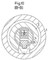
- Figur 10:
- Einen Schnitt nach B-B in
Figur 9. - Figur 11:
- Einen dritten axialen Schnitt durch das dritte Ausführungsbeispiel und
- Figur 12:
- Einen Querschnitt nach C-C in Figur 11.
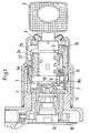
- Figure 1:
- An axial section through a motor vehicle steering wheel lock with a lock cylinder according to the invention.
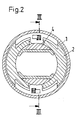
- Figure 2:
- A cross section through the castle.
- Figure 3:
- A section according to III-III in Figure 2.
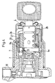
- Figure 4:
- An axial section through the embodiment.
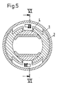
- Figure 5:
- A cross section through the second embodiment.
- Figure 6:
- A section according to VI-VI in Figure 5.
- Figure 7:
- An axial section through a third embodiment.
- Figure 8:
- A cross section according to AA in Figure 7.
- Figure 9:
- A second axial section through the third embodiment.
- Figure 10:
- A section according to BB in Figure 9.
- Figure 11:
- A third axial section through the third embodiment and
- Figure 12:
- A cross section according to CC in Figure 11.
Das Lenkschloß weist ein abgestuft zylindrisches Schloßgehäuse 1 auf, in dem koaxial ein Zylindergehäuse 2 gelagert ist, das aus einem inneren Zylindergehäuse 2a und einem äußeren Zylindergehäuse 2b besteht, die koaxial ineinander gesteckt sind.The steering lock has a stepped
Das innere Zylindergehäuse 2a weist radiale Ausnehmungen 2c auf, in die die plättchenförmigen Zuhaltungen 3 teilweise hineinragen, wenn ein falscher Schlüssel eingesteckt ist.The
Die Zuhaltungen 3 sind in quer angeordneten Ausnehmungen eines Zylinderkerns 4 radial verschieblich angeordnet. Der Zylinderkern 4 ist koaxial im Zylindergehäuse 2 verdrehbar gelagert und besitzt einen Längskanal für den Schlüssel 6.The
Das an sich bekannte Funktionsprinzip dieses Schließzylinders besteht darin, daß bei eingestecktem falschem Schlüssel die Zuhaltungen 3 das Zylindergehäsuse mit dem Zylinderkern drehfest verbinden, so daß bei Drehen des Schlüssels 6 sowohl der Zylinder- kern 4 als auch das Zylindergehäuse 2 verdreht werden. Hierbei überwindet das Zylindergehäuse eine Rastsperre und Zylinderkern und Zylindergehäuse sind frei verdrehbar durch einen falschen Schlüssel oder ein eingestecktes Einbruchswerkzeug.The known functional principle of this locking cylinder is that if the wrong key is inserted, the
Ist dagegen ein richtiger Schlüssel eingesteckt, so wird durch den Schlüssel der Zylinderkern 4 verdreht, aber nicht das Zylindergehäuse, da es durch die Rastsperre gehalten ist. In diesem Fall erzeugt die Relativbewegung des Zylinderkerns gegenüber dem Zylindergehäuse eine Bewegung eines Kuppelelementes, das den Zylinderkern mit einem weiteren Teil (Übertragungsteil 7) verbindet, das auf der Schlüsseleinführungsseite abgewandten Ende des Zylinderkerns angeordnet ist. Es kommt damit zu einem Kuppeln des Zylinderkerns 4 mit einem Übertragungsteil 7.If, on the other hand, a correct key is inserted, the
Im folgenden werden unterschiedliche Konstruktionsarten des Kuppelns des Zylinderkerns 4 mit dem Übertragungsteil 7 beschrieben, wenn der Zylinderkern 4 relativ gegenüber dem Zylindergehäuse 2 bewegt wird:Different types of construction of coupling the
Im Ausführungsbeispiel nach den Fig. 1 bis 3 ist der Zylinderkern 4 koaxial in einem inneren Zylindergehäuse 2a gelagert, das von einem äußeren Zylindergehäuse 2b koaxial umgeben ist, so daß das Zylindergehäuse zweiteilig ausgeführt ist. Diese Zweiteilung hat keine Bedeutung für die Funktion sondern wurde zur Erleichterung von Herstellung und Montage vorgenommen.In the embodiment according to FIGS. 1 to 3, the
Im inneren Ende des Zylinderkerns 4 ist ein achsparalleler Stift 8a als Kuppelelement gelagert, der in einer achsparallelen Bohrung 10 des Zylinderkerns 4 einliegt und dort von einer Feder 9 umgeben ist, die den Stift zur Schlüsseleinführungsseite hin beaufschlagt. Hierbei bildet das innere Ende des Zylinderkerns 4 einen Ringbund 4a, der seitlich vorsteht und aus dem der Stift 8a mit einem Kopf 11 vorragt, der in einer Ausnehmung 12 des inneren Zylindergehäuses 2a einliegt. Hierbei bildet die Ausnehmung 12 eine Schrägfläche, so daß bei einer Drehbewegung des Zylinderkerns 4 gegenüber dem inneren Zylindergehäuse 2a der Kopf 11 auf der Schrägfläche hochläuft und damit das dem Kopf 11 entgegengesetzte Ende des Stiftes 8a aus dem Ringbund 4a soweit heraustritt, daß dieses Ende in eine Ausnehmung 13 des Übertragungsteils 7 einfährt. Hierdurch wird der Zylinderkern 4 an das Übertragungsteil 7 angekuppelt, so daß mit Verdrehen des Schlüssels nicht nur der Zylinderkern 4, sondern auch das Übertragungsteil 7 und die hinter dem Übertragungsteil 7 liegenden Teile insbesondere den Steuernocken 14 verdreht, der mit seiner Steuernockenwelle 15 einen Sperriegelschieber 16 querverschiebt, der entweder selber den Sperriegel 17 bildet oder mit dem Sperriegel 17 verbunden ist, der in einer Ausnehmung 18 der Längsspindel 19 einfährt, um die Lenkung zu blockieren, siehe Fig. 7.In the inner end of the
Statt eines achsparallelen Stiftes 8a kann auch außermittig am Zylinderkern 4 bzw. am Ringbund 4a des Zylinderkerns ein Schwenkteil 8b als Kuppelelement drehbeweglich gelagert sein. Die Drehachse dieses Schwenkteils 8b liegt etwa tangential zur Außenseite des Zylinderkerns 4.Instead of an axially
Das Schwenkteil 8b hat die Form eines Kreissegmentes und liegt mit einer etwa radialen Seitenkante an einer inneren Stirnseite des Zylindergehäuses 2 an. Wird der Zylinderkern 4 gegenüber dem Zylindergehäuse 2 bei richtigem Schlüssel verdreht, so läuft die Kante 20 auf einer Kurve der Stirnseite des Zylindergehäuses entlang, wobei das Schwenkteil 8b verdreht wird, so daß die gegenüberliegende etwa radiale Kante 21 des Schwenkteils 8b in eine Ausnehmung des Übertragungsteils 7 eindringt, so daß der Zylinderkern das Übertragungsteil 7 mitverdreht, um über Zwischenteile der Sperriegel 17 zu betätigen.The
Bei dem Ausführungsbeispiel nach den Fig. 7 bis 12 besteht das Kuppelelement 8c aus einem quer insbesondere radial beweglichen Schieber 8c an dem eine Nase 22 seitlich achsparallel vorspringt, die auf einer Kurve 23 am Zylindergehäuse 2 entlang läuft. Wird der Zylinderkern 4 gegenüber dem Zylindergehäuse 2 verdreht, so wird der im Zylinderkern 4 quer verschieblich gelagerte Schieber 8c mitverdreht und die Nase 22 läuft auf der Kurve 23 entlang und wird radial nach außen bewegt. In der weitest außenliegenden Stellung dringt die Außenseite der Nase 22 bzw. ein äußerer Bereich des Schiebers 8c in eine Nut 23 des Steuernockens 14, so daß der Schieber 8c den Zylinderkern 4 an den Steuernocken 14 abkuppelt. Die weitere Drehbewegung des Zylinderkerns 4 führt damit zu einer entsprechenden Drehung des Steuernockens 14 und wiederum zu einer Betätigung des Sperriegels 17 als auch des elektrischen Drehschalters in den die Welle 15 hineinreicht.In the exemplary embodiment according to FIGS. 7 to 12, the
Das Ausführungsbeispiel nach den Fig. 7 bis 12 weist noch eine Sicherungsplatte 24 auf, die querbeweglich im Steuernocken 14 gelagert ist und dafür sorgt, daß der Steuernocken 14 am Zylinderkern 4 so sicher befestigt ist, daß er nicht bei einem gewaltsamen Aufbruch des Schlosses von der Drehschalterseite her entfernt werden kann.The embodiment of FIGS. 7 to 12 still has a locking
Bei diesen Längsschlüsseln ist es erforderlich, daß ein Zurückdrehen des Schlüssels und damit des Zylinderkerns in die Nullstellung nicht schon dazu führt, daß der Sperriegel in die Ausnehmung der Längsspindel einrasten kann. Diese Drehstellung des Zylinderkerns kurz vor dem Herausziehen des Schlüssels wird "Sperrbereitschaftsstellung" genannt. Eine Hubstange 25, die seitlich am Zylindergehäuse innerhalb des Schloßgehäuses gelagert ist, sorgt dafür, daß in dieser Sperrbereitschaftstellung der Steuernocken 14 in der zurückgedrehten Stellung gehalten wird, indem das innere Ende der Hubstange 25 an einem Anschlag des Steuernockens 14 anliegt. Ein im Zylinderkern 4 radial in der Nähe der Schlüsseleinführungsseite gelagerter Schieber 26 liegt mit einem Ende am Schlüssel und mit dem anderen Ende an der Hubstange 25 an und sorgt dafür, daß die Hubstange erst dann freigegeben wird, wenn der Schlüssel abgezogen ist. Statt der Ausführungsbeispiele nach Fig. 7 bis 12 dargestellten Hubstange 25 kann hierzu auch ein Hebel 26 seitlich am Zylindergehäuse gelagert werden wie dies die Ausführungsbeispiele nach Fig. 1 bis 6 zeigen.With these longitudinal keys it is necessary that turning the key and thus the cylinder core back to the zero position does not already result in the locking bolt being able to snap into the recess in the longitudinal spindle. This rotational position of the cylinder core shortly before the key is removed is called the "ready-to-lock position". A lifting
Das Schloß hat folgende Funktion:
Durch die Rutschkupplung bleibt der aus dem Gehäuse ragende Schließzylinder 4 bei falscher Betätigung oder bei Betätigung mit einem falschen Schließelement 6 radial freigängig, ohne einen Schließ-/Schaltvorgang zu bewirken. Nur der richtige Schlüssel 6 bewirkt, daß der Kern 4 und der Steuernocken 14 durch einen exzentrisch geführten Mitnehmer (Kupplelement 8a,8b oder 8c) gekuppelt werden und die Schließfunktion ermöglichen. Die Rutschkupplung erhöht die Sicherheit des Zündlenkschlosses, erschwert eine mutwillige Beschädigung mit einem falschen Schlüssel oder einem Aufbruchwerkzeug.The lock has the following functions:
Due to the slipping clutch, the
Bei einem falschen Schlüssel bleiben der Kern 4 und das Zylindergehäuse 2 durch die Zuhaltung/en 3 ein verbundenes formschlüssiges Element, das im Lenkschloßgehäuse 1 radial frei beweglich ist. Axial ist das formschlüssige Element durch einen Riegel 30 im Zylindergehäuse 2 positioniert. Der Riegel 30 gleitet im umlaufenden Einstich des Lenkschloßgehäuses 1.If the key is incorrect, the
Die Hubstange 25, geführt im Zylindergehäuse 2, wirkt als Raste mit der zum Lenkschloßgehäuse formschlüssigen Sicherungsscheibe 31 gegenüber dem Lenkschloßgehäuse 1 und läßt die Null-Stellung erkennen. Die Hubstange 25 behält die ursprüngliche Funktion bei, Schließung erst nach Schlüsselabzug. Das zylindrische Kernende gleitet frei in dem ruhenden Steuernocken 14 Die Hubstange 25 ist axial im Zylindergehäuse 2 geführt. Die RASTFUNKTION bewirkt einen Hub der Hubstange. Ein Zylinderstift 32 in der Hubstange 25, lotrecht zu der Kernmittelachse, reicht bis in die Nut im Kern 4. Rastet die Hubstange 25, so rastet auch der Zylinderstift 32. So werden Kern und Zylindergehäuse verriegelt. Dadurch wird der Schließzylinder, wenn er außerhalb der Rastenstellung der Hubstange steht und von dem richtigen Schlüssel betätigt wird, bis in die Rastenstellung (Nullstellung) der Hubstange 25 mitbewegt. Erst dann kann die Hubstange im Lenkschloßgehäuse 7 einrasten. Der Zylinderstift 32 der Hubstange entriegelt dadurch den Kern 4 und das Zylindergehäuse 2. Die normale Schließung kann eingeleitet werden.The lifting
Nach kurzer Schlüsseldrehbewegung, noch bevor die Kraftübertragung des Kerns 4 auf den Steuernocken 14 beginnt, verhindert die Nut 33 im Kern, in der der Zylinderstift 32 der Hubstange 25 gleitet. ein Ausweichen der Hubstange und verriegelt somit das Zylindergehäuse 2 mit dem Lenkschloßgehäuse 1. Die Nut 33 im Kern für den Zylinderstift 32 der Hubstange 25 garantiert zusätzlich die bisherige Hubfunktion der Hubstange falls diese durch die Reibung der Hubstange am Lenkschloßgehäuse beeinträchtigt würde
(SICHERUNG DES SCHLIESSVORGANGES BIS SCHLÜSSELABZUG = "Sperrbereitschaftsstellung").After a brief key rotation, even before the power transmission of the
(SECURING THE LOCKING PROCESS UNTIL KEY DRAWING = "Ready to lock").
Der richtige Schlüssel 6 ermöglicht das Verdrehen des Kernes 4 gegenüber dem Zylindergehäuse. Im zylindrischen Ende des Kernes 4 ist ein Mitnehmer 8c lotrecht zur Mittelachse geführt. Durch das Drehen des Kernes wird der Mitnehmer 8c in der Nut, die in der Planfläche am Ende des Zylindergehäuses 2 ist, extentrisch bewegt. Nach kurzer Drehbewegung entspricht der außermittig bewegte Mitnehmer 8c einer Passfeder, die den Stuernocken 14 zum Einsatz bringt. Bei weiterer Drehbewegung bleibt der Mitnehmer exzentrisch in gleichem Abstand zur Mittelachse in der Nut geführt.The
Das Zurückschalten funktioniert umgekehrt bis auf Anschlag in die Null-Stellung. Erst nach Schlüsselabzug federt die Hubstange 25 zurück und steht wieder frei zur Rastenfunktion.Switching back works in reverse up to the stop in the zero position. The lifting
Um eine Manipulierung am Steuernocken 14 vom Zündanlaßschalter her vorzubeugen, wird der Steuernocken von der Sicherungsplatte 24 axial gesichert. Somit wird verhindert, daß ein Dieb den Steuernocken mit einer Zange zieht und dreht, um das Lenkschloß zu entriegeln. Bei Schlüsselbetrieb wird die Sicherungsplatte 24 im Schlepp des Mitnehmers gezogen und der Steuernocken axial freigegeben.In order to prevent tampering with the
Claims (8)
Applications Claiming Priority (2)
| Application Number | Priority Date | Filing Date | Title |
|---|---|---|---|
| DE4233029 | 1992-10-01 | ||
| DE4233029A DE4233029C2 (en) | 1992-10-01 | 1992-10-01 | Locking cylinder |
Publications (2)
| Publication Number | Publication Date |
|---|---|
| EP0590330A1 true EP0590330A1 (en) | 1994-04-06 |
| EP0590330B1 EP0590330B1 (en) | 1999-04-07 |
Family
ID=6469395
Family Applications (1)
| Application Number | Title | Priority Date | Filing Date |
|---|---|---|---|
| EP93113967A Expired - Lifetime EP0590330B1 (en) | 1992-10-01 | 1993-09-01 | Lock cylinder |
Country Status (4)
| Country | Link |
|---|---|
| EP (1) | EP0590330B1 (en) |
| BR (1) | BR9303976A (en) |
| DE (2) | DE4233029C2 (en) |
| ES (1) | ES2131085T3 (en) |
Cited By (1)
| Publication number | Priority date | Publication date | Assignee | Title |
|---|---|---|---|---|
| WO2013014173A1 (en) * | 2011-07-25 | 2013-01-31 | Valeo Securite Habitacle | Anti-theft device for a steering column and associated steering column |
Families Citing this family (1)
| Publication number | Priority date | Publication date | Assignee | Title |
|---|---|---|---|---|
| DE10317449A1 (en) * | 2003-04-16 | 2004-11-04 | Aug. Winkhaus Gmbh & Co. Kg | Coupling device on double lock cylinder and double lock cylinder |
Citations (7)
| Publication number | Priority date | Publication date | Assignee | Title |
|---|---|---|---|---|
| US1582425A (en) * | 1924-08-25 | 1926-04-27 | Sewell Cushion Wheel Company | Wheel lock |
| US2049742A (en) * | 1933-04-22 | 1936-08-04 | Yale & Towne Mfg Co | Lock |
| US2086034A (en) * | 1935-08-09 | 1937-07-06 | Briggs & Stratton Corp | Lock |
| DE2605589A1 (en) * | 1976-02-12 | 1977-09-01 | Kolb Gmbh & Co Hans | Steering and ignition lock - with rotating key slot coupled to locking bolt by coupling bars alongside lock cylinder |
| DE2644000A1 (en) * | 1974-10-14 | 1977-09-15 | Sprecher & Schuh Ag | CYLINDER LOCK WITH MULTIPLE KEY REMOVAL FOR ONE ROTARY SWITCH |
| EP0212468A1 (en) * | 1985-08-08 | 1987-03-04 | Tomio Oota | Cylinder lock |
| EP0341132A1 (en) * | 1988-05-04 | 1989-11-08 | Valeo Neiman | Lock with a disconnectible rotor |
Family Cites Families (4)
| Publication number | Priority date | Publication date | Assignee | Title |
|---|---|---|---|---|
| JPS58112850A (en) * | 1981-12-26 | 1983-07-05 | Kokusan Kinzoku Kogyo Co Ltd | Steering lock device for car |
| FR2558883B1 (en) * | 1984-01-31 | 1987-02-27 | Dupart Jean | LOCK WITH ADDED SAFETY BLOCK, ARRANGED TO PREVENT ITS FRAUDULENT OPENING |
| DE3509834A1 (en) * | 1985-03-19 | 1986-10-02 | Neiman GmbH, 5657 Haan | STEERING LOCK |
| FR2583813B1 (en) * | 1985-06-19 | 1991-08-30 | Neiman Sa | CYLINDRICAL ROTOR LOCK CONTROLLING A DRIVE FINGER |
-
1992
- 1992-10-01 DE DE4233029A patent/DE4233029C2/en not_active Expired - Fee Related
-
1993
- 1993-09-01 DE DE59309497T patent/DE59309497D1/en not_active Expired - Fee Related
- 1993-09-01 EP EP93113967A patent/EP0590330B1/en not_active Expired - Lifetime
- 1993-09-01 ES ES93113967T patent/ES2131085T3/en not_active Expired - Lifetime
- 1993-09-30 BR BR9303976A patent/BR9303976A/en not_active IP Right Cessation
Patent Citations (7)
| Publication number | Priority date | Publication date | Assignee | Title |
|---|---|---|---|---|
| US1582425A (en) * | 1924-08-25 | 1926-04-27 | Sewell Cushion Wheel Company | Wheel lock |
| US2049742A (en) * | 1933-04-22 | 1936-08-04 | Yale & Towne Mfg Co | Lock |
| US2086034A (en) * | 1935-08-09 | 1937-07-06 | Briggs & Stratton Corp | Lock |
| DE2644000A1 (en) * | 1974-10-14 | 1977-09-15 | Sprecher & Schuh Ag | CYLINDER LOCK WITH MULTIPLE KEY REMOVAL FOR ONE ROTARY SWITCH |
| DE2605589A1 (en) * | 1976-02-12 | 1977-09-01 | Kolb Gmbh & Co Hans | Steering and ignition lock - with rotating key slot coupled to locking bolt by coupling bars alongside lock cylinder |
| EP0212468A1 (en) * | 1985-08-08 | 1987-03-04 | Tomio Oota | Cylinder lock |
| EP0341132A1 (en) * | 1988-05-04 | 1989-11-08 | Valeo Neiman | Lock with a disconnectible rotor |
Cited By (5)
| Publication number | Priority date | Publication date | Assignee | Title |
|---|---|---|---|---|
| WO2013014173A1 (en) * | 2011-07-25 | 2013-01-31 | Valeo Securite Habitacle | Anti-theft device for a steering column and associated steering column |
| FR2978403A1 (en) * | 2011-07-25 | 2013-02-01 | Valeo Securite Habitacle | ANTI-THEFT DEVICE FOR STEERING COLUMN AND STEERING COLUMN THEREFOR |
| CN103917419A (en) * | 2011-07-25 | 2014-07-09 | 法雷奥安全座舱公司 | Anti-theft device for steering column and associated steering column |
| RU2583423C2 (en) * | 2011-07-25 | 2016-05-10 | Валео Секюрите Абитакль | Antitheft device for steering column and corresponding steering column |
| US9789852B2 (en) | 2011-07-25 | 2017-10-17 | Valeo Securite Habitacle | Anti-theft device for a steering column and associated steering column |
Also Published As
| Publication number | Publication date |
|---|---|
| DE4233029A1 (en) | 1994-04-07 |
| BR9303976A (en) | 1994-04-05 |
| EP0590330B1 (en) | 1999-04-07 |
| DE59309497D1 (en) | 1999-05-12 |
| DE4233029C2 (en) | 2001-10-04 |
| ES2131085T3 (en) | 1999-07-16 |
Similar Documents
| Publication | Publication Date | Title |
|---|---|---|
| EP0722029B1 (en) | Motor vehicle door lock with rotational centrally controlled locking system | |
| EP0755476B1 (en) | Locking device, especially for motor vehicle locking | |
| EP0819810B1 (en) | Fitting for a lock | |
| DE2711061A1 (en) | LOCK ACTUATED BY A KEY UNDER THE INFLUENCE OF A MAGNETIC FIELD ASSIGNED TO THIS LOCK | |
| EP0752044A1 (en) | Cylinder lock designed particularly for vehicles | |
| DE4016779A1 (en) | Antitheft steering wheel lock - has torque limiting drive shaft with split construction | |
| EP1381744A2 (en) | Locking cylinder | |
| DE2632908B2 (en) | Motor vehicle steering lock | |
| DE4041134C1 (en) | Car lock cylinder with core guide - which carriers a radially displaceable follower, spring-loaded up to radial abutment on guide | |
| DE2617798A1 (en) | LOCK WITH ROTATING CYLINDER CORE | |
| DE4233029C2 (en) | Locking cylinder | |
| EP1671002B1 (en) | Cylinder for a lock, particularly in vehicles | |
| EP0349738B1 (en) | Locking cylinder | |
| WO2001042596A1 (en) | Closing device for closing functions in vehicles in particular | |
| DE1555886C3 (en) | Anti-theft devices for motor vehicles | |
| DE2605589C3 (en) | Motor vehicle steering lock | |
| DE4307339A1 (en) | Steering lock for vehicles | |
| DE102018131779A1 (en) | Locking device | |
| EP0768220B1 (en) | Steering lock for a motor vehicle | |
| EP1193359B1 (en) | Closure device | |
| DE102022114905A1 (en) | Lock with a bolt that can be rotated by an operating element | |
| DE977251C (en) | Security device against theft of motor vehicles | |
| DE19621327C1 (en) | Steering wheel lock for motor vehicle | |
| EP4112856A1 (en) | Lock with a bolt rotatable by an actuating element | |
| DE102019128176A1 (en) | Switching device and parking lock device |
Legal Events
| Date | Code | Title | Description |
|---|---|---|---|
| PUAI | Public reference made under article 153(3) epc to a published international application that has entered the european phase |
Free format text: ORIGINAL CODE: 0009012 |
|
| AK | Designated contracting states |
Kind code of ref document: A1 Designated state(s): DE ES FR GB IT |
|
| 17P | Request for examination filed |
Effective date: 19940329 |
|
| 17Q | First examination report despatched |
Effective date: 19950413 |
|
| GRAG | Despatch of communication of intention to grant |
Free format text: ORIGINAL CODE: EPIDOS AGRA |
|
| GRAG | Despatch of communication of intention to grant |
Free format text: ORIGINAL CODE: EPIDOS AGRA |
|
| GRAH | Despatch of communication of intention to grant a patent |
Free format text: ORIGINAL CODE: EPIDOS IGRA |
|
| GRAH | Despatch of communication of intention to grant a patent |
Free format text: ORIGINAL CODE: EPIDOS IGRA |
|
| GRAA | (expected) grant |
Free format text: ORIGINAL CODE: 0009210 |
|
| AK | Designated contracting states |
Kind code of ref document: B1 Designated state(s): DE ES FR GB IT |
|
| GBT | Gb: translation of ep patent filed (gb section 77(6)(a)/1977) |
Effective date: 19990421 |
|
| REF | Corresponds to: |
Ref document number: 59309497 Country of ref document: DE Date of ref document: 19990512 |
|
| REG | Reference to a national code |
Ref country code: ES Ref legal event code: FG2A Ref document number: 2131085 Country of ref document: ES Kind code of ref document: T3 |
|
| ET | Fr: translation filed | ||
| PLBE | No opposition filed within time limit |
Free format text: ORIGINAL CODE: 0009261 |
|
| STAA | Information on the status of an ep patent application or granted ep patent |
Free format text: STATUS: NO OPPOSITION FILED WITHIN TIME LIMIT |
|
| 26N | No opposition filed | ||
| REG | Reference to a national code |
Ref country code: GB Ref legal event code: IF02 |
|
| PGFP | Annual fee paid to national office [announced via postgrant information from national office to epo] |
Ref country code: GB Payment date: 20040827 Year of fee payment: 12 |
|
| PGFP | Annual fee paid to national office [announced via postgrant information from national office to epo] |
Ref country code: DE Payment date: 20040908 Year of fee payment: 12 |
|
| PGFP | Annual fee paid to national office [announced via postgrant information from national office to epo] |
Ref country code: ES Payment date: 20040914 Year of fee payment: 12 |
|
| PGFP | Annual fee paid to national office [announced via postgrant information from national office to epo] |
Ref country code: FR Payment date: 20040930 Year of fee payment: 12 |
|
| PG25 | Lapsed in a contracting state [announced via postgrant information from national office to epo] |
Ref country code: IT Free format text: LAPSE BECAUSE OF NON-PAYMENT OF DUE FEES;WARNING: LAPSES OF ITALIAN PATENTS WITH EFFECTIVE DATE BEFORE 2007 MAY HAVE OCCURRED AT ANY TIME BEFORE 2007. THE CORRECT EFFECTIVE DATE MAY BE DIFFERENT FROM THE ONE RECORDED. Effective date: 20050901 Ref country code: GB Free format text: LAPSE BECAUSE OF NON-PAYMENT OF DUE FEES Effective date: 20050901 |
|
| PG25 | Lapsed in a contracting state [announced via postgrant information from national office to epo] |
Ref country code: ES Free format text: LAPSE BECAUSE OF NON-PAYMENT OF DUE FEES Effective date: 20050902 |
|
| PG25 | Lapsed in a contracting state [announced via postgrant information from national office to epo] |
Ref country code: DE Free format text: LAPSE BECAUSE OF NON-PAYMENT OF DUE FEES Effective date: 20060401 |
|
| GBPC | Gb: european patent ceased through non-payment of renewal fee |
Effective date: 20050901 |
|
| PG25 | Lapsed in a contracting state [announced via postgrant information from national office to epo] |
Ref country code: FR Free format text: LAPSE BECAUSE OF NON-PAYMENT OF DUE FEES Effective date: 20060531 |
|
| REG | Reference to a national code |
Ref country code: FR Ref legal event code: ST Effective date: 20060531 |
|
| REG | Reference to a national code |
Ref country code: ES Ref legal event code: FD2A Effective date: 20050902 |