EP0590185A1 - Elektromagnetischer Motor - Google Patents
Elektromagnetischer Motor Download PDFInfo
- Publication number
- EP0590185A1 EP0590185A1 EP92116693A EP92116693A EP0590185A1 EP 0590185 A1 EP0590185 A1 EP 0590185A1 EP 92116693 A EP92116693 A EP 92116693A EP 92116693 A EP92116693 A EP 92116693A EP 0590185 A1 EP0590185 A1 EP 0590185A1
- Authority
- EP
- European Patent Office
- Prior art keywords
- rotor
- recited
- electromagnetic motor
- magnets
- perimeter
- Prior art date
- Legal status (The legal status is an assumption and is not a legal conclusion. Google has not performed a legal analysis and makes no representation as to the accuracy of the status listed.)
- Granted
Links
Images

Classifications
-
- H—ELECTRICITY
- H02—GENERATION; CONVERSION OR DISTRIBUTION OF ELECTRIC POWER
- H02K—DYNAMO-ELECTRIC MACHINES
- H02K29/00—Motors or generators having non-mechanical commutating devices, e.g. discharge tubes or semiconductor devices
- H02K29/14—Motors or generators having non-mechanical commutating devices, e.g. discharge tubes or semiconductor devices with speed sensing devices
-
- H—ELECTRICITY
- H02—GENERATION; CONVERSION OR DISTRIBUTION OF ELECTRIC POWER
- H02K—DYNAMO-ELECTRIC MACHINES
- H02K1/00—Details of the magnetic circuit
- H02K1/06—Details of the magnetic circuit characterised by the shape, form or construction
- H02K1/22—Rotating parts of the magnetic circuit
- H02K1/27—Rotor cores with permanent magnets
- H02K1/2793—Rotors axially facing stators
- H02K1/2795—Rotors axially facing stators the rotor consisting of two or more circumferentially positioned magnets
- H02K1/2796—Rotors axially facing stators the rotor consisting of two or more circumferentially positioned magnets where both axial sides of the rotor face a stator
-
- H—ELECTRICITY
- H02—GENERATION; CONVERSION OR DISTRIBUTION OF ELECTRIC POWER
- H02K—DYNAMO-ELECTRIC MACHINES
- H02K21/00—Synchronous motors having permanent magnets; Synchronous generators having permanent magnets
- H02K21/12—Synchronous motors having permanent magnets; Synchronous generators having permanent magnets with stationary armatures and rotating magnets
- H02K21/24—Synchronous motors having permanent magnets; Synchronous generators having permanent magnets with stationary armatures and rotating magnets with magnets axially facing the armatures, e.g. hub-type cycle dynamos
-
- H—ELECTRICITY
- H02—GENERATION; CONVERSION OR DISTRIBUTION OF ELECTRIC POWER
- H02K—DYNAMO-ELECTRIC MACHINES
- H02K29/00—Motors or generators having non-mechanical commutating devices, e.g. discharge tubes or semiconductor devices
- H02K29/06—Motors or generators having non-mechanical commutating devices, e.g. discharge tubes or semiconductor devices with position sensing devices
- H02K29/10—Motors or generators having non-mechanical commutating devices, e.g. discharge tubes or semiconductor devices with position sensing devices using light effect devices
Definitions
- This invention relates to the field of electromagnetic motors, and specifically to electromagnetic motors in which rotors having permanent magnets mounted thereon are rotated by means of alternating phase currents supplied to electromagnet stators.
- An object of the invention is to provide mechanical motive power.
- An additional object of the invention is to provide high speed mechanical motive power, wherein electrical input power consumption is reduced as mechanical speed of rotation increases.
- an apparatus in accordance with the invention comprising a rotor having a perimeter, a plurality of magnets mounted on the perimeter of the rotor, an electromagnet disposed adjacent to the perimeter of the motor, and means for magnetizing the electromagnet and for changing a polarity of the electromagnet in a predetermined phase relationship with rotation of the rotor, whereby magnetic attraction and repulsion between the electromagnet and the plurality of magnets cause the rotor to rotate.
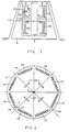
- FIG 1 shows a front view of an apparatus according to the invention.
- a rotor 2, shown in an edge view, is supported by and rotates about an axle 4.
- the rotor 2 is preferably made of a non-magnetically conductive material such as a neodymium iron boron alloy.
- the axle 4 is supported in a base 6 at its ends.
- One or more electromagnets 8 are mounted by suitable means so that they are disposed near the rotor 2. While four electromagnets 8 are shown in Figure 1, any suitable number may be employed. Also, while the electromagnets 8 may all be disposed on a same side of the rotor 2, in the present embodiment in Figure 1, electromagnets 8 are disposed on either side of the rotor 2.
- the electromagnets are U-shaped. Coils 10 are wound around the electromagnets 8. AS will be described in detail below, suitable electric current is provided to the coils 10 to cause magnetic fields to be induced in the electromagnets 8. Depending on the direction of the current through a coil 10, a given end of an electromagnet 8 may be either a north pole or a south pole. A grounded shield 12 may be employed to enclose the entire apparatus.
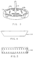
- Figures 2 and 3 show a more detailed view of the rotor 2 according to a first preferred embodiment of the invention.
- Figure 2 shows a side view of the rotor 2
- Figure 3 shows a perspective view of the rotor 2.
- a plurality of slots 16 are provided around a perimeter 14 of the rotor 2.
- the slots are arranged around the perimeter 14 end-to-end to suggest the shape of a polygon.
- 8 slots are shown, thus suggesting the shape of an octagon.
- the slots extend partly through the rotor 2.
- the slots accommodate permanent magnets which are mounted to the rotor 2 and rotate therewith.
- the slots 16 may be trapezoidal in shape.
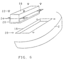
- Figures 4 and 5 show top and side views, respectively, of a permanent magnet 18 which may be inserted in the slots 16.
- the magnet is shaped as a trapezoidal prism.
- the top view as shown in Figure 4 shows a trapezoidal shape.
- the top and bottom boundaries of the magnet are parallel, and the left and right sides are slightly farther apart at the top than at the bottom. Accordingly, as shown more clearly in Figure 2, the trapezoidal shapes fit into the slots 16 on the rotor 2 to form a series running end-to-end around the perimeter 14 of the rotor 2.
- the magnets may be in a standard rectangular shape.
- the magnets 18 have two elongated opposing faces which serve as magnetic poles. The magnets are inserted into the slots 16 or otherwise mounted onto the rotor 2 such that a desired one of the poles faces outward. Thus, a magnetic dipole axis running through the two poles of one of the magnets 18 will be approximately parallel to an axis of rotation of the rotor 2.
- eight magnets 18 on each side of the rotor 2 are shown, the number of magnets 18 used may vary depending on factors such as the size of the overall structure.
- the power of the electromagnetic motor according to the invention is related to the length of the magnets 18.
- eight of the magnets 18 are disposed end-to-end around the perimeter of the rotor 2, so each magnet 18 has a length corresponding to 45° of the circumference of the rotor 2.
- a different number of magnets could be similarly employed.
- each magnet 18 would have a length corresponding to 60° of the circumference of the rotor 2.
- the power of such a device would be correspondingly increased relative to a device having eight magnets.
- each trapezoidal face of the trapezoidal prism is a pole of the magnet 18.
- Figure 5 shows that the upper portion of the magnet is the north pole.
- the letter N is repeated along the length of the view of Figure 5 to indicate that the upper portion, in its entirety, is the north pole.
- the lower portion of the view of Figure 5 is the south pole.
- Figure 4 is a top view and Figure 5 is a side view of the magnet 18, it will be understood that the view of Figure 4 is an end-on view of the north pole.
- magnets 18 are inserted in the slots 16 such that the outward facing surface of any given magnet, in its entirety, is one pole of the magnet.
- the inner facing surface is the other pole of the magnet.
- Figure 6 shows a partial exploded view of a portion of the rotor 2 according to a second embodiment of the invention.
- a permanent magnet 18 substantially similar to that of Figures 4 and 5 is bonded to a tray 20.
- the tray 20 accommodates fasteners 22 for removably fastening the tray 20 to the rotor 2.
- the fasteners 22 are screws.
- a slot 16 is provided for accommodating the magnet 18 inside the tray 20. However, the slot 16 may be omitted if a flush mounted tray is employed.
- the fasteners 22 are inserted through holes in tabs 24 on the tray 20 to holes 26 in the rotor 2.
- the holes 26 may have screw threads. Accordingly, a magnet bonded to a tray may be quickly and easily removed or replaced.
- magnets 18 are inserted in the slots of the rotor 2 (or otherwise mounted) such that, in sequence around the perimeter 14, alternating poles are facing outward.
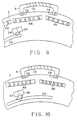
- Figure 2 also shows a plurality of regions on the surface of the rotor 2 which bear reflective material 28.
- the reflective material 28 is preferably disposed at a radial distance from the axis 4 such that, as the rotor 2 rotates, at a given fixed position relative to the axis 4, alternating regions of reflective material and regions lacking reflective material on the rotor 2 are adjacent to the given position.
- the reflective material 28 may be used in conjunction with a photosensitive device for determining an angular position of the rotor 2.
- FIG. 1 shows, in schematic form, a photosensitive device 30 which is supported by a suitable supporting means 32 mounted to the frame 6, such as a bracket or arm.
- the photosensitive device 30 may be a photocell, photodiode, phototransistor, or other suitable electronic device.
- an output signals from the photosensitive device 30 will vary between two different values, depending upon whether a portion of the reflective material 28 is adjacent to the photosensitive device 30.
- the output signal may be employed to control the polarity of current supplied through the coils 10 to the electromagnets 8, as described below.
- the output signal may also be used for other suitable purposes such as for providing an input signal to a tachometer.
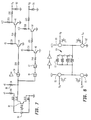
- FIG. 7 there is shown a schematic diagram of a drive circuit including the photosensitive device 30 of Figure 1, and additional circuitry for providing drive current to the coils 10 of the electromagnets 8.
- the photosensitive device 30 is shown as a phototransistor which conducts current according to the amount of light which impinges on it.
- a light emitting diode (LED) 34 is mounted adjacent to the phototransistor 30.
- the LED 34 may also be mounted on the supporting means 32 shown in Fig. 1, or may be otherwise supported.
- the LED 34 directs a beam of light against the surface of the rotor 2. During time intervals when the reflective material 28 is adjacent to the phototransistor 30 and the LED 34, the light is reflected onto the phototransistor 30, causing it to conduct current.
- a resistor 36 is connected between a power supply voltage and the collector of the phototransistor 30. Accordingly, a voltage at the collector of the phototransistor 30 varies between high and low values depending on whether light from the LED 34 is reflecting off a portion of the reflective material 28.
- the collector of the transistor 30 is coupled to inputs of logic gates 38, 40.
- the logic gate 40 has an output which is coupled to an input of a logic gate 42.
- the logic gates 38, 40, 42 are shown as two-input NAND gates. It is common practice to employ a multi-input inverted-output gate such as a two-input NAND gate as an inverter by coupling an input signal to all of the inputs and the NAND gate. While a wide variety of logic devices may be used in place of the logic gates 38, 40, 42, the objective here is to provide two output signals which follow the collector of the phototransistor 30 and which are in opposite logic states.
- Outputs of the, logic gates 38, 42 are coupled to amplifiers. Each amplifier is shown as having two transistor stages.
- the amplifier coupled to the output of the logic gate 38 includes transistors 44, 46, and the amplifier coupled to the output of the logic gate 42 includes the transistors 48, 50.
- Outputs of the amplifiers at the collectors of the transistors 46 and 50 are coupled through resistors to cathodes of Zener diodes 52, 54, respectively.
- the Zener diodes 52, 54 are coupled such that, when a high voltage is received from the transistors 46 or 50, the Zener diodes will be reverse biased, and will thus serve as voltage regulators in accordance with their reverse bias breakdown voltages.
- Outputs of the circuit of Figure 7 are shown as G A and G B respectively. Signals appearing at these outputs vary between high and low voltage states in accordance with whether a piece of reflective material 28 is adjacent to the phototransistor 30.
- Figure 8 is a schematic representation of the coils 10 of the electromagnets 8. Additional drive circuitry is shown, which is coupled to receive the voltages G A and G B from the circuit of Figure 7. The drive circuit provides current to the coils 10. The direction of the current through the coils 10 is determined by which of the signals G a or G b is high.
- the portion of the drive circuit shown in Figure 8 includes four power MOSFETs (metal oxide-semiconductor field effect transistors) 56, 58, 60, 62.
- drains of the power MOSFETs 56, 60 are coupled to a power supply, which produces a suitable supply voltage, such as 12, 24 or 36 volts, and sources of the power MOSFETs 58, 62 are coupled to ground.
- Sources of the power MOSFETS 56, 60 are coupled to drains of the power MOSFETS 58, 62, respectively.
- the source of the power MOSFET 56 is also coupled to a first end of each of the coils 10.
- the coils 10 are coupled in parallel, as shown.
- Switches collectively labeled as 64 are provided between the second ends of each of the coils 10 so that one or more of the coils 10 may be disconnected from the circuit by opening the appropriate switch 64. Thus, certain ones of the coils may normally be left disconnected, but may be connected as necessary to provide extra power.
- the second end of the first coil and of any subsequent coils 10 coupled by means of these switches 64 are coupled to the source of the power MOSFET 60.
- the rotor 2 is carrying magnets shown specifically as 64, 66, and 68 past poles of the electromagnet 8.
- the rotation of the rotor 2 also has carried a piece of reflective material 28 mounted on the rotor 2 into the path of a beam of light emitted by the LED 34. The light reflects off the reflective material 28 and strikes the photosensitive device 30.
- the first pole 72 (north) is to the left of center of the permanent magnet 66.
- the north pole of the permanent magnet 66 is facing outward, adjacent to the pole 72 of the electromagnet 8. Accordingly, magnetic repulsion is taking place between the magnet 66 and the pole 72. Since the pole 72 is to the left of center, magnetic repulsion between 72 and the magnet 66 urges the magnet 66 and, hence, the rotor 2 to rotate clockwise. Also, the pole 72 is farther away from the magnet 64 than it is from the magnet 68. The two magnets both have south poles both facing outward. Since the pole 72 is closer to the magnet 68 than it is to the magnet 64, magnetic attraction between the pole 72 and the magnet 68 also urges the rotor to rotate clockwise. Through a similar analysis, it will be seen that magnetic attraction and repulsion involving the pole 74 of the electromagnet also urges clockwise rotation.
- poles 72 and 74 are now to the left of center of the magnets 68 and 66, respectively. If current were still flowing in the coil 10 in the same direction as before, then the pole 72 would still be a north pole and the pole 74 would still be a south pole. Since these poles are to the left of center of the respective permanent magnets, magnetic attraction and repulsion would cause a breaking effect or urge counterclockwise rotation of the rotor 2.
- the beam of light from the LED 34 has passed beyond the end of the reflective material 28.
- the beam of light thus is no longer being reflected onto the photosensitive device 30.
- current now flows in the opposite direction through the coil 10 as before.
- the pole 72 is now a south pole
- the pole 74 is now a north pole.
- magnetic repulsion between the south pole 72 and the south pole of the magnet 68 urges the rotor 2 to rotate clockwise.
- magnetic attraction between the south pole 72 and north poles of magnets 66 and 70 also urges the rotor 2 to rotate clockwise.
- the pole 74 is true for the pole 74.
- An apparatus in accordance with the invention may employed for generating electric current, as well as for producing mechanical motive power.
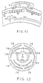
- a rotor 73 similar to that of Figure 2, but further including additional magnets 76.
- the magnets 76 may be of an essentially similar type to the magnets 18, and may be mounted similarly on the rotor 2.
- the magnets 76 are disposed closer to the axle 4 than the magnets 18.
- the magnets 76 are used for generating electric power. Since torque is applied to the rotor 2 by magnetic forces between the magnets 18 and the electromagnets 10 as described above, positioning the magnets 76 relative close to the axle 4 facilitates generating electric power.
- FIG 13 there is shown a perspective view of the rotor 73 of Figure 12. Magnets 18 and electromagnets 8 similar to those of the previously described embodiments are shown. To simplify the drawing, the strips of reflective material 28 have been omitted, but it will be understood that they are present in essentially similar configurations to those shown in Figure 12. The magnets 76 are also shown forming a series end-to-end around the axle 4, as shown in Figure 12.
- magnets 18 and 76, strips of reflective material 28, electromagnets 8, and other components on or adjacent to the visible face of the rotor 73 in Figures 12 and 13 may also be on the opposite face of the rotor 73, although that face is not in view in Figures 12 and 13.
- the magnets 76 rotate as well.
- a plurality of coils 78 which are shown in schematic form. The coils 78 are mounted by a suitable means to be positioned adjacent to the magnets 76.
- the magnets 76 rotate along with the rotor 73, by Faraday's law electric current is induced in the coils 78.
- Six magnets 76 and four coils 78 are shown in the side of the rotor 73 visible in Figure 12. It will be understood, however, that magnets 76 and coils 78 may be disposed on the other side of the rotor 73 as well. Also, the number and configuration of the magnets 76 and the coils 78 may vary within the spirit and scope of the invention.
- the coils 78 may be any suitable structure for inducing current from a moving magnetic field. For instance, the coils 78 could be structures similar to the electromagnets 8.
- the reflective material 28 is disposed on the rotor 2 in positions such that reflection or non-reflection of the beam of light from the LED 34 causes current to flow through the coils 10 to cause clockwise rotation of the rotor 2 in a desired direction. It will be understood to one of ordinary skill in the art that the exact number and dimensions of permanent magnets, the exact dimensions of the electromagnets 8, the position of the LED 34 and the photosensitive device 30, and the disposition of the reflective material 28 on the rotor 2 may all vary within the spirit and scope of the invention.
- the angular distance between the poles 72 and 74 of a typical U-shaped electromagnet may not correspond exactly to the angular dimensions of one of the permanent magnets on the rotor 2.
- the pole 72 of the electromagnet may be exactly centered on a magnet such as the magnet 66, while, due to differing dimensions, the pole 74 is to the right or to the left of center of the adjacent magnet, such as 64.
- analysis might show that for certain ranges of angular displacement of the rotor 2, a given polarity of the electromagnet 8 might urge rotation of the rotor in one direction, while for other ranges of angular displacement rotation in the opposite direction might be urged.
- the system in accordance with the invention as described above would be capable of achieving a high speed of rotation of the rotor 2 on the order of tens of thousands of rotations per minute (rpm). Speeds of approximately 10,000 rpm and over 20,000 rpm have been produced in devices according to the preferred embodiment.
- the apparatus would be "closed loop" system in that changes in the current flow through the coil 10 to produce changes in the polarity of the electromagnet 8 would result from angular displacement of the rotor 2.
- current will continuously flow through the coils 10. The direction of flow depends on whether the device 30 is receiving the light.
Priority Applications (9)
| Application Number | Priority Date | Filing Date | Title |
|---|---|---|---|
| US07/656,798 US5191255A (en) | 1991-02-19 | 1991-02-19 | Electromagnetic motor |
| AU26075/92A AU655321B2 (en) | 1991-02-19 | 1992-09-29 | Electromagnetic motor |
| EP92116693A EP0590185B1 (de) | 1991-02-19 | 1992-09-30 | Elektromagnetischer Motor |
| DK92116693.0T DK0590185T3 (da) | 1991-02-19 | 1992-09-30 | Elektromagnetisk motor |
| DE69211992T DE69211992T2 (de) | 1991-02-19 | 1992-09-30 | Elektromagnetischer Motor |
| AT92116693T ATE140108T1 (de) | 1991-02-19 | 1992-09-30 | Elektromagnetischer motor |
| ES92116693T ES2091377T3 (es) | 1991-02-19 | 1992-09-30 | Motor electromagnetico. |
| CA002080162A CA2080162A1 (en) | 1991-02-19 | 1992-10-08 | Electromagnetic motor |
| JP4314053A JPH06153479A (ja) | 1991-02-19 | 1992-10-29 | 電磁モータ |
Applications Claiming Priority (3)
| Application Number | Priority Date | Filing Date | Title |
|---|---|---|---|
| US07/656,798 US5191255A (en) | 1991-02-19 | 1991-02-19 | Electromagnetic motor |
| EP92116693A EP0590185B1 (de) | 1991-02-19 | 1992-09-30 | Elektromagnetischer Motor |
| JP4314053A JPH06153479A (ja) | 1991-02-19 | 1992-10-29 | 電磁モータ |
Publications (2)
| Publication Number | Publication Date |
|---|---|
| EP0590185A1 true EP0590185A1 (de) | 1994-04-06 |
| EP0590185B1 EP0590185B1 (de) | 1996-07-03 |
Family
ID=27234535
Family Applications (1)
| Application Number | Title | Priority Date | Filing Date |
|---|---|---|---|
| EP92116693A Expired - Lifetime EP0590185B1 (de) | 1991-02-19 | 1992-09-30 | Elektromagnetischer Motor |
Country Status (9)
| Country | Link |
|---|---|
| US (1) | US5191255A (de) |
| EP (1) | EP0590185B1 (de) |
| JP (1) | JPH06153479A (de) |
| AT (1) | ATE140108T1 (de) |
| AU (1) | AU655321B2 (de) |
| CA (1) | CA2080162A1 (de) |
| DE (1) | DE69211992T2 (de) |
| DK (1) | DK0590185T3 (de) |
| ES (1) | ES2091377T3 (de) |
Cited By (3)
| Publication number | Priority date | Publication date | Assignee | Title |
|---|---|---|---|---|
| GB2338840A (en) * | 1998-04-16 | 1999-12-29 | Snr John Patrick Ettridge | Winding/core arrangement in an electric motor |
| EP1287602A1 (de) * | 2000-04-11 | 2003-03-05 | Light Sciences Corporation | Kontaktlose energietransfervorrichtung |
| WO2004073143A1 (en) * | 2003-02-11 | 2004-08-26 | Randall Family Trust | Electric machine having an axial air gap |
Families Citing this family (47)
| Publication number | Priority date | Publication date | Assignee | Title |
|---|---|---|---|---|
| US5436518A (en) * | 1992-01-03 | 1995-07-25 | Nihon Riken Co., Ltd. | Motive power generating device |
| US6348751B1 (en) | 1997-12-12 | 2002-02-19 | New Generation Motors Corporation | Electric motor with active hysteresis-based control of winding currents and/or having an efficient stator winding arrangement and/or adjustable air gap |
| US6849984B2 (en) * | 1998-10-13 | 2005-02-01 | Raymond Joseph Gallant | Magnetically driven wheel for use in radial/rotary propulsion system having an energy recovery feature |
| US7105972B2 (en) * | 1998-10-13 | 2006-09-12 | Gallant Raymond J | Controller and magnetically driven wheel for use in a radial/rotary propulsion system |
| US6707212B2 (en) * | 1998-12-21 | 2004-03-16 | Gustaf Bergmark | Electrical machine |
| US6538356B1 (en) | 2000-06-28 | 2003-03-25 | Robert M. Jones | Electric machine using composite blade structure |
| ITBZ20010043A1 (it) * | 2001-09-13 | 2003-03-13 | High Technology Invest Bv | Generatore elettrico azionato da energia eolica. |
| US6492754B1 (en) | 2001-10-31 | 2002-12-10 | Electric Boat Corporation | Magnet retention channel arrangement for high speed operation |
| US6548932B1 (en) | 2001-10-31 | 2003-04-15 | Electric Boat Corporation | Nonmagnetic magnet retention channel arrangement for high speed rotors |
| TWI299936B (en) * | 2002-05-13 | 2008-08-11 | Sunyen Co Ltd | Apparatus for re-generating a driving force |
| US7233088B2 (en) * | 2003-01-17 | 2007-06-19 | Magnetic Torque International, Ltd. | Torque converter and system using the same |
| US7268454B2 (en) * | 2003-01-17 | 2007-09-11 | Magnetic Torque International, Ltd. | Power generating systems |
| JP4502667B2 (ja) * | 2004-03-04 | 2010-07-14 | エドワーズ株式会社 | 磁気軸受装置及び該磁気軸受装置を搭載したターボ分子ポンプ |
| US20100127579A1 (en) * | 2004-08-20 | 2010-05-27 | Dumitru Bojiuc | Magnetically levitated transport system |
| US7834503B2 (en) * | 2004-08-20 | 2010-11-16 | Clearwater Holdings, Ltd. | Immersed windings, monopole field, electromagnetic rotating machine |
| US7348703B2 (en) * | 2004-08-20 | 2008-03-25 | Dumitru Bojiuc | Monopole field electric motor-generator with switchable coil configuration |
| US7791242B2 (en) * | 2004-08-20 | 2010-09-07 | Clearwater Holdings, Ltd. | DC induction electric motor-generator |
| US20070252033A1 (en) * | 2004-08-20 | 2007-11-01 | Dumitru Bojiuc | Discoidal flying craft |
| US20060038456A1 (en) * | 2004-08-20 | 2006-02-23 | Dumitru Bojiuc | Monopole field electric motor generator |
| US7808142B2 (en) * | 2004-10-27 | 2010-10-05 | E3 Solutions, Llc | Multivariable generator and method of using the same |
| US20060111191A1 (en) * | 2004-11-19 | 2006-05-25 | Magnetic Torque International | Torque transfer system and method of using the same |
| US7291944B2 (en) * | 2005-01-12 | 2007-11-06 | Wilt Jr Herman F | Electromagnetic engine |
| US8074922B2 (en) * | 2005-08-22 | 2011-12-13 | Dumitru Bojiuc | Discoidal flying craft |
| US8074579B1 (en) | 2005-08-22 | 2011-12-13 | Dumitru Bojiuc | Magnetically levitated transport system |
| ITBZ20050062A1 (it) * | 2005-11-29 | 2007-05-30 | High Technology Invest Bv | Rotore a magneti permanenti per generatori e motori elettrici |
| ITBZ20050063A1 (it) * | 2005-11-29 | 2007-05-30 | High Technology Invest Bv | Pacco di lamierini per generatori e motori elettrici e procedimento per la sua attuazione |
| ATE461366T1 (de) * | 2005-09-21 | 2010-04-15 | High Technology Invest Bv | Lagerdichtungsanordung mit labyrinthdichtungs- und schraubdichtungskombination |
| CA2703862A1 (en) * | 2007-10-29 | 2009-05-07 | Daniel Farb | Rotational magnetic propulsion motors |
| EP2081276A1 (de) * | 2008-01-21 | 2009-07-22 | Marco Cipriani | Elektromagnetische Vorrichtung mit umschaltbarem Generator- oder Motorbetrieb |
| EP2146422A1 (de) | 2008-06-06 | 2010-01-20 | Jose Salvador Olmo | Elektrischer Motor selbstgespeist durch einen externen Wechselstrom / Gleichstrom-Generator |
| ITMI20081122A1 (it) | 2008-06-19 | 2009-12-20 | Rolic Invest Sarl | Generatore eolico provvisto di un impianto di raffreddamento |
| IT1390758B1 (it) | 2008-07-23 | 2011-09-23 | Rolic Invest Sarl | Generatore eolico |
| IT1391939B1 (it) * | 2008-11-12 | 2012-02-02 | Rolic Invest Sarl | Generatore eolico |
| IT1391770B1 (it) | 2008-11-13 | 2012-01-27 | Rolic Invest Sarl | Generatore eolico per la generazione di energia elettrica |
| IT1392804B1 (it) * | 2009-01-30 | 2012-03-23 | Rolic Invest Sarl | Imballo e metodo di imballo per pale di generatori eolici |
| IT1393937B1 (it) * | 2009-04-09 | 2012-05-17 | Rolic Invest Sarl | Aerogeneratore |
| IT1393707B1 (it) | 2009-04-29 | 2012-05-08 | Rolic Invest Sarl | Impianto eolico per la generazione di energia elettrica |
| IT1394723B1 (it) | 2009-06-10 | 2012-07-13 | Rolic Invest Sarl | Impianto eolico per la generazione di energia elettrica e relativo metodo di controllo |
| IT1395148B1 (it) * | 2009-08-07 | 2012-09-05 | Rolic Invest Sarl | Metodo e apparecchiatura di attivazione di una macchina elettrica e macchina elettrica |
| IT1397081B1 (it) | 2009-11-23 | 2012-12-28 | Rolic Invest Sarl | Impianto eolico per la generazione di energia elettrica |
| IT1398060B1 (it) | 2010-02-04 | 2013-02-07 | Wilic Sarl | Impianto e metodo di raffreddamento di un generatore elettrico di un aerogeneratore, e aerogeneratore comprendente tale impianto di raffreddamento |
| IT1399201B1 (it) | 2010-03-30 | 2013-04-11 | Wilic Sarl | Aerogeneratore e metodo di rimozione di un cuscinetto da un aerogeneratore |
| IT1399511B1 (it) | 2010-04-22 | 2013-04-19 | Wilic Sarl | Generatore elettrico per un aerogeneratore e aerogeneratore equipaggiato con tale generatore elettrico |
| ITMI20110377A1 (it) | 2011-03-10 | 2012-09-11 | Wilic Sarl | Macchina elettrica rotante per aerogeneratore |
| ITMI20110375A1 (it) | 2011-03-10 | 2012-09-11 | Wilic Sarl | Turbina eolica |
| ITMI20110378A1 (it) | 2011-03-10 | 2012-09-11 | Wilic Sarl | Macchina elettrica rotante per aerogeneratore |
| IT201600131306A1 (it) * | 2016-12-27 | 2018-06-27 | Hdm S R L | Motore Brushless |
Citations (9)
| Publication number | Priority date | Publication date | Assignee | Title |
|---|---|---|---|---|
| DE1907822A1 (de) * | 1969-02-17 | 1970-08-20 | Harry Gaus | Antriebsverfahren fuer Schallplattenspieler |
| US3917988A (en) * | 1974-08-07 | 1975-11-04 | Magna Motor Inc | Selectively variable timing means for a brushless electric motor |
| DE2424254A1 (de) * | 1974-05-18 | 1976-04-08 | Papst Motoren Kg | Kollektorloser gleichstrommotor |
| BE867436A (nl) * | 1978-05-25 | 1978-09-18 | Clippel Lucien De | Elektrische motor |
| GB2006542A (en) * | 1977-10-20 | 1979-05-02 | Gen Tech Inc | Multi-votage and multi-frequency alternator/generator of modular construction |
| DE3230283A1 (de) * | 1982-08-14 | 1984-02-16 | Indramat GmbH, 8770 Lohr | Buerstenloser gleichstrommotor |
| US4578606A (en) * | 1984-12-13 | 1986-03-25 | Buehler Products, Inc. | Brushless DC electric motor and tachogenerator assembly |
| US4704555A (en) * | 1986-06-16 | 1987-11-03 | General Electric Company | Improved disc rotor assembly |
| DE4016693A1 (de) * | 1989-05-26 | 1990-11-29 | Diesel Kiki Co | Spiralscheiben-stroemungsmittelpumpe |
Family Cites Families (21)
| Publication number | Priority date | Publication date | Assignee | Title |
|---|---|---|---|---|
| US2993156A (en) * | 1956-05-24 | 1961-07-18 | Sprague Electric Co | Capacitor dielectric |
| US3646376A (en) * | 1970-05-01 | 1972-02-29 | Gen Electric | High-frequency tachometer generator |
| GB1368788A (en) * | 1970-12-28 | 1974-10-02 | Gujitsu Ltd | Electric stepping motor |
| US3696260A (en) * | 1971-08-02 | 1972-10-03 | Motorola Inc | Permanent magnet rotor structure |
| US3803433A (en) * | 1972-02-17 | 1974-04-09 | Gen Time Corp | Permanent magnet rotor synchronous motor |
| US4358697A (en) * | 1981-08-19 | 1982-11-09 | Siemens-Allis, Inc. | Two-pole permanent magnet synchronous motor rotor |
| US4565938A (en) * | 1983-06-13 | 1986-01-21 | Intra-Technology Associates, Inc. | Permanent magnet rotor toroidal generator and motor |
| US4701656A (en) * | 1983-06-13 | 1987-10-20 | Intratechnology Associates, Inc. | Electromechanical device with slotted stator |
| US4459501A (en) * | 1983-06-13 | 1984-07-10 | Intra-Technology Assoc. Inc. | Toroidal generator and motor with radially extended magnetic poles |
| US4625135A (en) * | 1983-07-19 | 1986-11-25 | The Garrett Corporation | Permanent magnet rotor |
| GB8414953D0 (en) * | 1984-06-12 | 1984-07-18 | Maghemite Inc | Brushless permanent magnet dc motor |
| GB2161992B (en) * | 1984-07-17 | 1988-01-20 | Rolls Royce & Ass | Rotary actuator |
| US4814654A (en) * | 1984-10-12 | 1989-03-21 | Gerfast Sten R | Stator or rotor based on permanent magnet segments |
| US4806834A (en) * | 1987-04-16 | 1989-02-21 | Donald Goodman | Electrical circuit for inductance conductors, transformers and motors |
| DE3729298A1 (de) * | 1987-09-02 | 1989-03-23 | Pran Magnettechnik Europ Gmbh | Vorrichtung zur energieumwandlung |
| JPS6464165A (en) * | 1987-09-04 | 1989-03-10 | Fuji Electric Co Ltd | Disk driving use spindle motor |
| JPH0755037B2 (ja) * | 1988-05-13 | 1995-06-07 | 株式会社日立製作所 | 永久磁石式同期電動機 |
| US4837474A (en) * | 1988-08-12 | 1989-06-06 | Camatec Corporation | D.C. motor |
| US4922145A (en) * | 1988-11-17 | 1990-05-01 | Eastman Kodak Company | Stepper motor |
| AU632850B2 (en) * | 1989-09-11 | 1993-01-14 | Z.W. Engineering Pty. Ltd. | Electromagnetic machine |
| US4996457A (en) * | 1990-03-28 | 1991-02-26 | The United States Of America As Represented By The United States Department Of Energy | Ultra-high speed permanent magnet axial gap alternator with multiple stators |
-
1991
- 1991-02-19 US US07/656,798 patent/US5191255A/en not_active Expired - Fee Related
-
1992
- 1992-09-29 AU AU26075/92A patent/AU655321B2/en not_active Ceased
- 1992-09-30 DK DK92116693.0T patent/DK0590185T3/da active
- 1992-09-30 ES ES92116693T patent/ES2091377T3/es not_active Expired - Lifetime
- 1992-09-30 EP EP92116693A patent/EP0590185B1/de not_active Expired - Lifetime
- 1992-09-30 DE DE69211992T patent/DE69211992T2/de not_active Expired - Fee Related
- 1992-09-30 AT AT92116693T patent/ATE140108T1/de not_active IP Right Cessation
- 1992-10-08 CA CA002080162A patent/CA2080162A1/en not_active Abandoned
- 1992-10-29 JP JP4314053A patent/JPH06153479A/ja active Pending
Patent Citations (9)
| Publication number | Priority date | Publication date | Assignee | Title |
|---|---|---|---|---|
| DE1907822A1 (de) * | 1969-02-17 | 1970-08-20 | Harry Gaus | Antriebsverfahren fuer Schallplattenspieler |
| DE2424254A1 (de) * | 1974-05-18 | 1976-04-08 | Papst Motoren Kg | Kollektorloser gleichstrommotor |
| US3917988A (en) * | 1974-08-07 | 1975-11-04 | Magna Motor Inc | Selectively variable timing means for a brushless electric motor |
| GB2006542A (en) * | 1977-10-20 | 1979-05-02 | Gen Tech Inc | Multi-votage and multi-frequency alternator/generator of modular construction |
| BE867436A (nl) * | 1978-05-25 | 1978-09-18 | Clippel Lucien De | Elektrische motor |
| DE3230283A1 (de) * | 1982-08-14 | 1984-02-16 | Indramat GmbH, 8770 Lohr | Buerstenloser gleichstrommotor |
| US4578606A (en) * | 1984-12-13 | 1986-03-25 | Buehler Products, Inc. | Brushless DC electric motor and tachogenerator assembly |
| US4704555A (en) * | 1986-06-16 | 1987-11-03 | General Electric Company | Improved disc rotor assembly |
| DE4016693A1 (de) * | 1989-05-26 | 1990-11-29 | Diesel Kiki Co | Spiralscheiben-stroemungsmittelpumpe |
Cited By (7)
| Publication number | Priority date | Publication date | Assignee | Title |
|---|---|---|---|---|
| GB2338840A (en) * | 1998-04-16 | 1999-12-29 | Snr John Patrick Ettridge | Winding/core arrangement in an electric motor |
| EP1072084A1 (de) * | 1998-04-16 | 2001-01-31 | John Patrick Ettridge | Verbesserter elektromotor |
| EP1072084A4 (de) * | 1998-04-16 | 2001-10-17 | Ettridge John P | Verbesserter Elektromotor |
| GB2338840B (en) * | 1998-04-16 | 2003-07-09 | Snr John Patrick Ettridge | An Electrical Machine |
| EP1287602A1 (de) * | 2000-04-11 | 2003-03-05 | Light Sciences Corporation | Kontaktlose energietransfervorrichtung |
| EP1287602A4 (de) * | 2000-04-11 | 2003-09-03 | Light Sciences Corp | Kontaktlose energietransfervorrichtung |
| WO2004073143A1 (en) * | 2003-02-11 | 2004-08-26 | Randall Family Trust | Electric machine having an axial air gap |
Also Published As
| Publication number | Publication date |
|---|---|
| JPH06153479A (ja) | 1994-05-31 |
| EP0590185B1 (de) | 1996-07-03 |
| AU2607592A (en) | 1993-08-26 |
| DE69211992T2 (de) | 1997-01-23 |
| AU655321B2 (en) | 1994-12-15 |
| ATE140108T1 (de) | 1996-07-15 |
| US5191255A (en) | 1993-03-02 |
| DK0590185T3 (da) | 1996-11-11 |
| DE69211992D1 (de) | 1996-08-08 |
| ES2091377T3 (es) | 1996-11-01 |
| CA2080162A1 (en) | 1993-08-20 |
Similar Documents
| Publication | Publication Date | Title |
|---|---|---|
| US5191255A (en) | Electromagnetic motor | |
| US4563622A (en) | Simple brushless DC fan motor | |
| US3299335A (en) | Self-starting direct-current motors having no commutator | |
| US4972112A (en) | Brushless DC motor | |
| DE69317156T2 (de) | Elektronische Startvorrichtung für einen Synchronmotor mit permanent magnetischem Rotor | |
| KR960704383A (ko) | 영구자석을 갖는 전자기장치(electromagnetic machine with permanent magnet rotor) | |
| US3569806A (en) | Starting arrangement for solid-state commutated motor | |
| KR900001094A (ko) | 유체이동장치 구동용 전자정류 전기모우터와 그러한 모우터를 구비한 헤어드라이어 | |
| CA1180751A (en) | Control circuit of brushless dc motor | |
| US3493831A (en) | Brushless d.c. motor including starting means | |
| US4501997A (en) | Magnetization for brushless direct current outer rotor motor | |
| US3184623A (en) | Miniature electric motor | |
| US3599050A (en) | Brushless direct current motor | |
| US6066910A (en) | Commutator-less direct-current motor | |
| CA1205115A (en) | Simple brushless dc fan motor | |
| JPS5855747B2 (ja) | ブラシレスチヨクリユウモ−タ | |
| US4777415A (en) | Method of and circuitry for generating information relating to speed of rotation in a circuit for controlling a brushless direct-current motor in order to regulate it with digital controls | |
| JPH05284714A (ja) | 揺動ブラシレスアクチュエ−タ | |
| SU1644311A1 (ru) | Синхронный тахогенератор | |
| KR900007409B1 (ko) | 위치검출장치를 구비한 전동기 | |
| JPS6139842A (ja) | モ−タ | |
| KR900008923Y1 (ko) | 위치 검출장치를 구비한 전동기 | |
| KR900007228Y1 (ko) | 모터의 검지장치 | |
| SU1062830A1 (ru) | Вентильный электродвигатель | |
| JPS60118045A (ja) | 位置検知素子として磁電変換素子を使用しないブラシレスモ−タ |
Legal Events
| Date | Code | Title | Description |
|---|---|---|---|
| PUAI | Public reference made under article 153(3) epc to a published international application that has entered the european phase |
Free format text: ORIGINAL CODE: 0009012 |
|
| AK | Designated contracting states |
Kind code of ref document: A1 Designated state(s): AT BE DE DK ES FR GB IT NL SE |
|
| 17P | Request for examination filed |
Effective date: 19940721 |
|
| 17Q | First examination report despatched |
Effective date: 19941027 |
|
| GRAH | Despatch of communication of intention to grant a patent |
Free format text: ORIGINAL CODE: EPIDOS IGRA |
|
| GRAH | Despatch of communication of intention to grant a patent |
Free format text: ORIGINAL CODE: EPIDOS IGRA |
|
| GRAA | (expected) grant |
Free format text: ORIGINAL CODE: 0009210 |
|
| AK | Designated contracting states |
Kind code of ref document: B1 Designated state(s): AT BE DE DK ES FR GB IT NL SE |
|
| REF | Corresponds to: |
Ref document number: 140108 Country of ref document: AT Date of ref document: 19960715 Kind code of ref document: T |
|
| ITF | It: translation for a ep patent filed |
Owner name: DE DOMINICIS & MAYER S.R.L. |
|
| REF | Corresponds to: |
Ref document number: 69211992 Country of ref document: DE Date of ref document: 19960808 |
|
| ET | Fr: translation filed | ||
| REG | Reference to a national code |
Ref country code: ES Ref legal event code: FG2A Ref document number: 2091377 Country of ref document: ES Kind code of ref document: T3 |
|
| REG | Reference to a national code |
Ref country code: DK Ref legal event code: T3 |
|
| PLBE | No opposition filed within time limit |
Free format text: ORIGINAL CODE: 0009261 |
|
| STAA | Information on the status of an ep patent application or granted ep patent |
Free format text: STATUS: NO OPPOSITION FILED WITHIN TIME LIMIT |
|
| 26N | No opposition filed | ||
| PGFP | Annual fee paid to national office [announced via postgrant information from national office to epo] |
Ref country code: SE Payment date: 19980824 Year of fee payment: 7 Ref country code: DE Payment date: 19980824 Year of fee payment: 7 |
|
| PGFP | Annual fee paid to national office [announced via postgrant information from national office to epo] |
Ref country code: ES Payment date: 19980901 Year of fee payment: 7 |
|
| PGFP | Annual fee paid to national office [announced via postgrant information from national office to epo] |
Ref country code: AT Payment date: 19980902 Year of fee payment: 7 |
|
| PGFP | Annual fee paid to national office [announced via postgrant information from national office to epo] |
Ref country code: GB Payment date: 19980922 Year of fee payment: 7 |
|
| PGFP | Annual fee paid to national office [announced via postgrant information from national office to epo] |
Ref country code: DK Payment date: 19980923 Year of fee payment: 7 |
|
| PGFP | Annual fee paid to national office [announced via postgrant information from national office to epo] |
Ref country code: BE Payment date: 19980928 Year of fee payment: 7 |
|
| PGFP | Annual fee paid to national office [announced via postgrant information from national office to epo] |
Ref country code: NL Payment date: 19980930 Year of fee payment: 7 Ref country code: FR Payment date: 19980930 Year of fee payment: 7 |
|
| PG25 | Lapsed in a contracting state [announced via postgrant information from national office to epo] |
Ref country code: SE Free format text: THE PATENT HAS BEEN ANNULLED BY A DECISION OF A NATIONAL AUTHORITY Effective date: 19990929 |
|
| PG25 | Lapsed in a contracting state [announced via postgrant information from national office to epo] |
Ref country code: GB Free format text: LAPSE BECAUSE OF NON-PAYMENT OF DUE FEES Effective date: 19990930 Ref country code: DK Free format text: LAPSE BECAUSE OF NON-PAYMENT OF DUE FEES Effective date: 19990930 Ref country code: BE Free format text: LAPSE BECAUSE OF NON-PAYMENT OF DUE FEES Effective date: 19990930 Ref country code: AT Free format text: LAPSE BECAUSE OF NON-PAYMENT OF DUE FEES Effective date: 19990930 |
|
| PG25 | Lapsed in a contracting state [announced via postgrant information from national office to epo] |
Ref country code: ES Free format text: LAPSE BECAUSE OF NON-PAYMENT OF DUE FEES Effective date: 19991001 |
|
| BERE | Be: lapsed |
Owner name: MAGNETOSPHERIC POWER CORP. Effective date: 19990930 |
|
| PG25 | Lapsed in a contracting state [announced via postgrant information from national office to epo] |
Ref country code: NL Free format text: LAPSE BECAUSE OF NON-PAYMENT OF DUE FEES Effective date: 20000401 |
|
| GBPC | Gb: european patent ceased through non-payment of renewal fee |
Effective date: 19990930 |
|
| PG25 | Lapsed in a contracting state [announced via postgrant information from national office to epo] |
Ref country code: FR Free format text: LAPSE BECAUSE OF NON-PAYMENT OF DUE FEES Effective date: 20000531 |
|
| NLV4 | Nl: lapsed or anulled due to non-payment of the annual fee |
Effective date: 20000401 |
|
| REG | Reference to a national code |
Ref country code: DK Ref legal event code: EBP |
|
| EUG | Se: european patent has lapsed |
Ref document number: 92116693.0 |
|
| PG25 | Lapsed in a contracting state [announced via postgrant information from national office to epo] |
Ref country code: DE Free format text: LAPSE BECAUSE OF NON-PAYMENT OF DUE FEES Effective date: 20000701 |
|
| REG | Reference to a national code |
Ref country code: FR Ref legal event code: ST |
|
| REG | Reference to a national code |
Ref country code: ES Ref legal event code: FD2A Effective date: 20001013 |
|
| PG25 | Lapsed in a contracting state [announced via postgrant information from national office to epo] |
Ref country code: IT Free format text: LAPSE BECAUSE OF NON-PAYMENT OF DUE FEES;WARNING: LAPSES OF ITALIAN PATENTS WITH EFFECTIVE DATE BEFORE 2007 MAY HAVE OCCURRED AT ANY TIME BEFORE 2007. THE CORRECT EFFECTIVE DATE MAY BE DIFFERENT FROM THE ONE RECORDED. Effective date: 20050930 |