EP0589718A1 - Méthode d'alignement de plumes - Google Patents
Méthode d'alignement de plumes Download PDFInfo
- Publication number
- EP0589718A1 EP0589718A1 EP93307586A EP93307586A EP0589718A1 EP 0589718 A1 EP0589718 A1 EP 0589718A1 EP 93307586 A EP93307586 A EP 93307586A EP 93307586 A EP93307586 A EP 93307586A EP 0589718 A1 EP0589718 A1 EP 0589718A1
- Authority
- EP
- European Patent Office
- Prior art keywords
- alignment
- pen
- printer
- pattern
- user
- Prior art date
- Legal status (The legal status is an assumption and is not a legal conclusion. Google has not performed a legal analysis and makes no representation as to the accuracy of the status listed.)
- Granted
Links
Images


Classifications
-
- B—PERFORMING OPERATIONS; TRANSPORTING
- B41—PRINTING; LINING MACHINES; TYPEWRITERS; STAMPS
- B41J—TYPEWRITERS; SELECTIVE PRINTING MECHANISMS, i.e. MECHANISMS PRINTING OTHERWISE THAN FROM A FORME; CORRECTION OF TYPOGRAPHICAL ERRORS
- B41J2/00—Typewriters or selective printing mechanisms characterised by the printing or marking process for which they are designed
- B41J2/005—Typewriters or selective printing mechanisms characterised by the printing or marking process for which they are designed characterised by bringing liquid or particles selectively into contact with a printing material
- B41J2/01—Ink jet
- B41J2/21—Ink jet for multi-colour printing
- B41J2/2132—Print quality control characterised by dot disposition, e.g. for reducing white stripes or banding
- B41J2/2135—Alignment of dots
-
- B—PERFORMING OPERATIONS; TRANSPORTING
- B41—PRINTING; LINING MACHINES; TYPEWRITERS; STAMPS
- B41J—TYPEWRITERS; SELECTIVE PRINTING MECHANISMS, i.e. MECHANISMS PRINTING OTHERWISE THAN FROM A FORME; CORRECTION OF TYPOGRAPHICAL ERRORS
- B41J2/00—Typewriters or selective printing mechanisms characterised by the printing or marking process for which they are designed
- B41J2/005—Typewriters or selective printing mechanisms characterised by the printing or marking process for which they are designed characterised by bringing liquid or particles selectively into contact with a printing material
- B41J2/01—Ink jet
-
- B—PERFORMING OPERATIONS; TRANSPORTING
- B41—PRINTING; LINING MACHINES; TYPEWRITERS; STAMPS
- B41J—TYPEWRITERS; SELECTIVE PRINTING MECHANISMS, i.e. MECHANISMS PRINTING OTHERWISE THAN FROM A FORME; CORRECTION OF TYPOGRAPHICAL ERRORS
- B41J25/00—Actions or mechanisms not otherwise provided for
- B41J25/34—Bodily-changeable print heads or carriages
Definitions
- the present invention relates generally to plural pen alignment solutions for ink-jet printers. More particularly, the invention concerns such method and apparatus that provide a low-cost two pen alignment solution that user-interactively, semi-automatically compensates for misalignments between field replaceable monochrome, e.g. black, and tri-color, e.g. magenta, cyan and yellow, pens within an ink-jet printhead carriage.
- field replaceable monochrome e.g. black
- tri-color e.g. magenta, cyan and yellow
- the invented plural pen alignment solution involves user interaction with automatic pen alignment firmware to select the best alignment among a number of illustratively printed options.
- the alignment algorithm is invoked by a keystroke on the ink-jet printer's control panel, typically when a new pen is installed in the printer's carriage.
- the printer prints stored horizontal and vertical alignment test patterns that illustrate a range of alignment options including one each that should be optimal.
- the printer also prints a stored illustration of the printer's control panel keys that may be struck to make selected alignments. The user simply examines the printout, selects desired alignments and strikes the indicated key on the panel.
- Horizontal alignments are made in firmware by shifting the timing between nozzle firings in 300 dots per inch (300 dpi) increments.
- Vertical alignments are made in firmware by shifting the pixel image, i.e. selecting different nozzles for firing, also at 300 dpi resolution.
- the printer prints a page of alignment patterns illustrating the chosen alignments, which are stored in non-volatile memory.
- Fig. 1 illustrates a horizontal alignment test pattern that is printed in accordance with the preferred plural pen alignment solution.
- Fig. 2 illustrates a pictorial representation of a keypad that is printed in accordance with the invented solution.
- Fig. 3 illustrates a vertical alignment test pattern that is printed in accordance with the preferred solution.
- Fig. 4 illustrates a confirmation alignment pattern that is printed in accordance with the preferred solution.
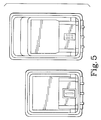
- Fig. 5 shows the physical layouts of a monochrome and a tricolor ink-jet pen's orifices.
- Fig. 1 shows plural instances of superposed first and second horizontal alignment patterns that are printed by a controller within an ink-jet printer as part of the invented plural-pen alignment method.
- the patterns will be understood to represent plural instances of a first stored alignment pattern that are in printed predefined positions on a page utilizing a first pen, e.g. a black pen, which first pattern labeled K includes a collinear set of spaced line segments.
- first pen e.g. a black pen
- first pattern labeled K includes a collinear set of spaced line segments.
- the plural instances themselves are preferably laterally, evenly spaced.
- Corresponding plural instances of a second stored alignment pattern are printed utilizing a second pen, e.g.
- magenta pen which second pattern labeled M includes a collinear set of spaced line segments that generally or nominally are in alignment with, i.e. collinear with, and interpose, the spaced line segments of the first pattern.
- Each of the plural instances of superposed first and second patterns includes and is identified by one or more pattern identifiers, or printed indicia, e.g. the printed numbers 1 through 7 printed adjacent the designated superposed patterns. As will be seen by reference to Fig. 2, such indicia correspond with user selectable keys on a keypad that part of the ink-jet printer's control panel.
- Fig. 1 illustrates that the plural instances of second alignment pattern M are printed in a range of predefined positions relative to the first pattern instances with a predefined offset, or horizontal shift, of pattern M between successive instances, e.g. the second pattern starts to the left of first pattern K in instance 1 and progressively shifts to the right so that it end to the right of first pattern K in instance 7.
- the successive shifts may be seen to be transverse, and preferably perpendicular, to axes defined by the collinear segments of second alignment pattern M.
- the predefined relative positions may be seen nominally to include at least one of the positions of the first pattern, e.g. the superposed patterns labeled 4 in Fig. 1 nominally are aligned.
- Superposed first and second patterns K, M may be understood to define a number of inter-pen alignment options that are useful to the user in selecting a desired alignment, for example, after installing a new pen into the printer's printhead carriage.
- the offsets in Fig. 1 are greatly exaggerated to render them more easily discernable and understandable.
- the horizontal offsets preferably provide a range of approximately ⁇ 3 dots at 300 dpi.
- the offset of the middle horizontal alignment pattern in Fig. 1 typically would not exhibit the intentionally exaggerated offset, but instead would exhibit perfect or near-perfect alignment between the first and second superposed patterns, thereby achieving the purpose of the invented method and apparatus.
- a pictorial representation of the printer's control console keypad is shown.
- Such a pictorial representation preferably is printed with, and most preferably on the same page as are, the plural instances of superposed alignment patterns K, M, when the invented alignment process is invoked.
- the keypad representation includes selected keys of the keypad identified by, thus visually to promote an association with, printed indicia corresponding with the printed, superposed patterns-adjacent, identifying indicia shown in Fig. 1 to identify the plural superposed alignment pattern instances that represent inter-pen alignment options.
- the printed key indicia are the numbers 1 through 7 within circles indicating by the arrows the corresponding keys.
- any printed symbol may be used as a pattern identifier so long as there is an associable selection identifier having a corresponding printed symbol in the pictorial representation.
- letters may be used instead of numbers, or graphic symbols may be used instead of alphanumeric symbols.
- the pattern instances may be printed within the corresponding keys of the pictorial representation, as a printed symbol recognizable to the user as indicating which key selection will result in which alignment selection.
- color code the keys of the pictorial representation, or even the alignment patterns themselves e.g. using various primitive color combinations to print the second alignment patterns
- first and second alignment patterns 1 through 7 of Fig. 1 and the pictorial representation of the keypad of Fig. 2 are printed on a page of printer paper, preferably along with suitable printed instructions to the user (not shown) to make a selection of the alignment option that is seen to be most desirable, the user inputs a selected key from the keypad by any suitable manual desired alignment selection means, e.g. by depressing the key on the printer's keypad that corresponds with the desired alignment.
- manual selection means include plural selection identifiers associable with the plural pattern identifiers.
- the printer's controller reads the keyed input from the user, and correlates the key positional information illustrated in Fig. 2 with the alignment pattern positional information illustrated in Fig. 1.
- the controller Responsive to the key selection by the user, stores in a preferably non-volatile memory location the chosen alignment criteria, or information regarding the predefined offset corresponding with the user-inputted key. For example, if the user selects key 4, then the controller stores in memory the predefined offset information corresponding with the printed second alignment pattern of instance 4 of Fig. 1. Thereafter, i.e. after the alignment procedure is complete, the printer's controller utilizes this stored predefined offset corresponding with the second pen for all printing that is destined therefor.
- the result is semi-automatic, user-interactive inter-pen alignment by which the user is able to participate in the selection of the inter-pen alignment or registration. If the tri-color pen is placed in the printer's carriage at a slight lateral offset from the already installed black pen, i.e. either too close to or too far from the black pen, nevertheless near perfect inter-pen alignment can be had when ink-jet printing because the controller, with the user's help, adjusts the timing of its horizontal ink-jet firing sequences as between the black and the tri-color pen so that extremely close alignment or registration in the printed output is maintained. It will be appreciated that horizontal alignment only is illustrated in Figs. 1 and 2, whereas preferably vertical alignment also is provided.
- Fig. 3 illustrates a variation on the superposed first and second alignment patterns shown in Fig. 1 that facilitates vertical, in addition to horizontal, inter-pen alignment.
- Fig. 3 which represents a second page of printed output of the inter-pen alignment method
- plural instances of a first stored alignment pattern are printed utilizing a first pen, e.g. a black pen, with the first pattern again including a set of collinear, spaced line segments.
- plural instances of a second stored alignment pattern are printed utilizing a second pen, with the second pattern including a set of collinear spaced line segments nominally collinear with and interposing the spaced line segments of the first pattern, and with a predefined offset of the second pattern relative to the first between the successive instances of the first.
- first patterns labeled K
- second patterns labeled M
- each superposed pattern instance is identified by one or more printed indicia such as numbers 1 through 7.
- the superposed collinear line segments extend along horizontal axes (perpendicular with those printed during the horizontal alignment phase), or parallel with the printhead's scan axis.
- the superposed patterns represent a predefined range of vertical alignment options.
- the keyboard representation of Fig. 2 is printed, preferably on the same page as the vertical alignment patterns. The user is instructed as before to choose the desired alignment pattern instance by depressing the correspondingly numbered key on the printer's operator console keypad.
- information regarding the predefined offset corresponding with the selected pattern instance is stored in preferably non-volatile memory and thereafter utilized for printing by the second pen, e.g. the tri-color pen that printed the magenta segments (labeled M in Fig. 3).
- the second pen e.g. the tri-color pen that printed the magenta segments (labeled M in Fig. 3).
- vertical alignment in accordance with the preferred method of the invention is accomplished by pixel or orifice shifting to-be-printed images prior to printing, which will be described by reference to Fig. 5.
- first and second alignment patterns include both vertical and horizontal line segments, thereby defining respectively an array of horizontal and vertical inter-pen alignment options and providing respectively for a horizontal and a vertical alignment user selection.
- FIG. 4 shows a page that is printed by the printer's controller after the user has made desired horizontal and vertical alignment selections.
- a box and a cross are printed in accordance with the preferred method, again with collinear spaced line segments being printed by the first pen and with interposing and now more accurately aligned and collinear spaced line segments printed by the second pen.
- K for black
- M for magenta
- the controller preferably prints an alignment pattern based thereon as confirmation of the user's selection.
- the alignment pattern does not represent the desired horizontal and vertical alignment, the user may simply repeat the above-described alignment process until a desired alignment, as indicated by the confirmation printout, is achieved.
- the successive predefined horizontal and vertical offsets illustrated, respectively, in Figs. 1 and 3 define an offset range that has been predetermined to correspond to a range of possible inter-pen alignments within the printhead carriage, as determined by analyzing printer manufacturing tolerances.
- manufacturing tolerances may be higher, and thus the ink-jet printer cost may be lower, because of the inter-pen alignment method of the invention.
- the preferred method is user-interactive, semi-automatic, and implemented in firmware executed by the printer's existing controller, its provision imposes negligible cost on the purchaser and user of the printer. It is believed that ink-jet printer users are eager to participate in the inter-pen alignment process, which is infrequently required and which builds user confidence in high print quality.
- Fig. 5 shows the two-pen ink-jet printer printhead configuration including the nozzle or orifice layout for each pen (with greatly exaggerated inter-orifice spacing, for the sake of clarity).
- the range over which successive horizontal and vertical second alignment patterns are printed with offsets or positions, as illustrated in Figs. 1 and 3, are defined to a great extent by the geometries of the printhead's pens and the carriage that fixedly locates them relative to one another.
- the pens necessarily must be only temporarily fixedly captured within the printhead carriage. This need creates the possibility of inter-pen misalignment or mispositioning over a finite, predefined range best described as a lateral separation variance of the nominal separation of the "home" position orifices of the individual pens.
- the pens as shown are side by side in the printer's carriage, in nominally fixed, absolute and relative positions in the horizontal and vertical axes. Because their fixed positions within the carriage are only nominally determinable, due to the relatively high manufacturing tolerances that make replacement possible, the pens may be described as being positioned relative to one another within a predefined vertical and horizontal range. With this range defined, it is a simple matter to predefine the range of offsets represented by the succession of plural instances of relatively shifted second alignment patterns associated with the tri-color pen the output of which is labeled M in Figs. 1 and 3 so that it is associable with the range of pen alignment or position possibilities.
- the tri-color pen on the right of Fig. 5 will be understood to represent a "paper's eye” view of the pen. The same is true for the black pen shown on the left of Fig. 5.
- the two pens' home orifices nominally are separated center to center by approximately 34 millimeters (34 mm).
- the tricolor pen has three identical but differently positioned sets of bi-line orifices, one for each of the magenta, cyan and yellow ink reservoirs contained therein.
- the black pen appears from Fig. 5 to have a singular oval set of orifices, but in fact, it too has two columns of operative orifices, generally as described above regarding the tri-color pen (the oval-closing end orifices are non-printing).
- the printhead carriage containing the pens passes from right to left in Fig. 5, or perpendicularly to the long axes of the columnar, bi-line orifice sets.
- Offsets are accomplished by simply bit shifting, or pixel shifting, the to-be-printed images by up to ⁇ 3 pixels prior to printing.
- the alignment patterns are so created, as are normal images printed after a desired, user-selected offset is inputted during vertical alignment.
- horizontal alignment is accomplished by time shifting, i.e. advancing or retarding, the firing of the ink jets.
- time shifting straightforwardly is performed by the controller executing firmware resident in a read-only memory (ROM) therein.
- the invented plural pen alignment solution is generally applicable to pen alignment problems that heretofore have been solved in complicated and expensive ways.
Applications Claiming Priority (2)
| Application Number | Priority Date | Filing Date | Title |
|---|---|---|---|
| US95106792A | 1992-09-25 | 1992-09-25 | |
| US951067 | 1992-09-25 |
Publications (2)
| Publication Number | Publication Date |
|---|---|
| EP0589718A1 true EP0589718A1 (fr) | 1994-03-30 |
| EP0589718B1 EP0589718B1 (fr) | 1997-01-08 |
Family
ID=25491213
Family Applications (1)
| Application Number | Title | Priority Date | Filing Date |
|---|---|---|---|
| EP19930307586 Expired - Lifetime EP0589718B1 (fr) | 1992-09-25 | 1993-09-24 | Méthode d'alignement de plumes |
Country Status (3)
| Country | Link |
|---|---|
| EP (1) | EP0589718B1 (fr) |
| JP (1) | JPH06226964A (fr) |
| DE (1) | DE69307237T2 (fr) |
Cited By (21)
| Publication number | Priority date | Publication date | Assignee | Title |
|---|---|---|---|---|
| EP0709213A3 (fr) * | 1994-10-28 | 1996-09-04 | Canon Kk | Procédé et appareil pour tête de correction et imprimante utilisant cette tête |
| EP0867298A2 (fr) * | 1997-03-28 | 1998-09-30 | Canon Kabushiki Kaisha | Dispositif d'impression et procédé d'impression de motifs de contrÔle |
| EP0874329A2 (fr) * | 1997-04-24 | 1998-10-28 | Seiko Epson Corporation | Méthode et dispositif d'alignement d'impression |
| EP0934831A1 (fr) * | 1997-11-17 | 1999-08-11 | Hewlett-Packard Company | Appareil d'impression à jet d'encre avec système d'alignement et méthode |
| EP0945279A2 (fr) * | 1998-03-24 | 1999-09-29 | Pitney Bowes Inc. | Machine de traitement de courrier avec prévention des pertes de fonds postaux |
| EP0978390A1 (fr) * | 1998-08-03 | 2000-02-09 | Hewlett-Packard Company | Calibration de tête d'impression à jet d'encre |
| EP0858049A3 (fr) * | 1997-02-06 | 2000-04-05 | Hewlett-Packard Company | Positionnement des points d'impression dans une imprimante à jet d'encre |
| EP0895869A3 (fr) * | 1997-07-31 | 2000-05-17 | Seiko Epson Corporation | Procédé d'impression d'un motif d'essai et dispositif correspondant |
| EP0947323A3 (fr) * | 1998-04-03 | 2000-05-31 | Canon Kabushiki Kaisha | Méthode d'ajustement des positions de points d'impression et dispositif d'impression |
| EP0953452A3 (fr) * | 1998-04-03 | 2000-05-31 | Canon Kabushiki Kaisha | Procédé d'ajustement de la position de l'impression par points et appareil d'impression |
| US6164749A (en) * | 1997-03-17 | 2000-12-26 | Hewlett-Packard Company | Method for user alignment of a color printer |
| FR2801835A1 (fr) * | 1999-12-03 | 2001-06-08 | Imaje Sa | Procede et imprimante avec controle d'avance substrat |
| FR2801836A1 (fr) | 1999-12-03 | 2001-06-08 | Imaje Sa | Imprimante a fabrication simplifiee et procede de realisation |
| EP1002651A3 (fr) * | 1998-11-19 | 2002-04-03 | Sharp Kabushiki Kaisha | Imprimante sérielle et méthode pour ajuster le déplacement du support d'enregistrement |
| US6450607B1 (en) * | 2000-09-15 | 2002-09-17 | Lexmark International, Inc. | Alignment method for color ink jet printer |
| US6532026B2 (en) | 1998-04-03 | 2003-03-11 | Canon Kabushiki Kaisha | Adjustment method of dot printing positions and a printing apparatus |
| WO2003022592A1 (fr) * | 2001-09-10 | 2003-03-20 | Seiko Epson Corporation | Appareil et procede de depot par jet d'encre |
| EP1566955A3 (fr) * | 2004-02-11 | 2006-11-22 | Hewlett-Packard Development Company, L.P. | Procédé et appareil pour générer une cible de calibration destinée à un scanner et pour calibrer un scanner avec cette cible |
| CN100371169C (zh) * | 2003-12-03 | 2008-02-27 | 三星电子株式会社 | 用于控制在图像形成装置中的喷嘴位置的方法 |
| CN104512103A (zh) * | 2013-10-07 | 2015-04-15 | 佳能株式会社 | 打印设备和打印位置调整方法 |
| US9221284B2 (en) * | 2012-12-05 | 2015-12-29 | Ricoh Company, Ltd. | Image forming apparatus, method for forming test pattern, and computer program product |
Families Citing this family (2)
| Publication number | Priority date | Publication date | Assignee | Title |
|---|---|---|---|---|
| JP3738758B2 (ja) | 2002-09-30 | 2006-01-25 | ブラザー工業株式会社 | 画像形成装置 |
| US7936365B2 (en) | 2004-07-19 | 2011-05-03 | Samsung Electronics Co., Ltd. | Printing method and apparatus using shuttle thermal print head |
Citations (4)
| Publication number | Priority date | Publication date | Assignee | Title |
|---|---|---|---|---|
| DE3233425A1 (de) * | 1982-09-09 | 1984-04-05 | Olympia Werke Ag, 2940 Wilhelmshaven | Matrixdrucker mit einem auswechselbaren druckkopf |
| EP0257570A2 (fr) * | 1986-08-25 | 1988-03-02 | Siemens Aktiengesellschaft | Méthode d'alignement des injecteurs d'une tête d'impression à jet d'encre dans un dispositif d'enregistrement à encre et circuit électronique adapté à la mise en oeuvre de cette méthode |
| US5049898A (en) * | 1989-03-20 | 1991-09-17 | Hewlett-Packard Company | Printhead having memory element |
| US5109239A (en) * | 1989-01-31 | 1992-04-28 | Hewlett-Packard Company | Inter pen offset determination and compensation in multi-pen ink jet printing systems |
-
1993
- 1993-09-24 EP EP19930307586 patent/EP0589718B1/fr not_active Expired - Lifetime
- 1993-09-24 DE DE1993607237 patent/DE69307237T2/de not_active Expired - Fee Related
- 1993-09-27 JP JP23976793A patent/JPH06226964A/ja active Pending
Patent Citations (4)
| Publication number | Priority date | Publication date | Assignee | Title |
|---|---|---|---|---|
| DE3233425A1 (de) * | 1982-09-09 | 1984-04-05 | Olympia Werke Ag, 2940 Wilhelmshaven | Matrixdrucker mit einem auswechselbaren druckkopf |
| EP0257570A2 (fr) * | 1986-08-25 | 1988-03-02 | Siemens Aktiengesellschaft | Méthode d'alignement des injecteurs d'une tête d'impression à jet d'encre dans un dispositif d'enregistrement à encre et circuit électronique adapté à la mise en oeuvre de cette méthode |
| US5109239A (en) * | 1989-01-31 | 1992-04-28 | Hewlett-Packard Company | Inter pen offset determination and compensation in multi-pen ink jet printing systems |
| US5049898A (en) * | 1989-03-20 | 1991-09-17 | Hewlett-Packard Company | Printhead having memory element |
Cited By (42)
| Publication number | Priority date | Publication date | Assignee | Title |
|---|---|---|---|---|
| US6036297A (en) * | 1994-10-28 | 2000-03-14 | Canon Kabushiki Kaisha | Method and apparatus for correcting printhead, printhead correction by this apparatus, and printer using this printhead |
| EP0709213A3 (fr) * | 1994-10-28 | 1996-09-04 | Canon Kk | Procédé et appareil pour tête de correction et imprimante utilisant cette tête |
| EP0858049A3 (fr) * | 1997-02-06 | 2000-04-05 | Hewlett-Packard Company | Positionnement des points d'impression dans une imprimante à jet d'encre |
| US6164749A (en) * | 1997-03-17 | 2000-12-26 | Hewlett-Packard Company | Method for user alignment of a color printer |
| EP0867298A2 (fr) * | 1997-03-28 | 1998-09-30 | Canon Kabushiki Kaisha | Dispositif d'impression et procédé d'impression de motifs de contrÔle |
| US6084606A (en) * | 1997-03-28 | 2000-07-04 | Canon Kabushiki Kaisha | Printing apparatus and check pattern printing method |
| EP0867298A3 (fr) * | 1997-03-28 | 1998-11-18 | Canon Kabushiki Kaisha | Dispositif d'impression et procédé d'impression de motifs de contrÔle |
| EP0874329A3 (fr) * | 1997-04-24 | 1999-05-06 | Seiko Epson Corporation | Méthode et dispositif d'alignement d'impression |
| US6322191B1 (en) | 1997-04-24 | 2001-11-27 | Seiko Epson Corporation | Method of adjusting printing position, printing apparatus using the same, and recording medium having program for the same |
| EP0874329A2 (fr) * | 1997-04-24 | 1998-10-28 | Seiko Epson Corporation | Méthode et dispositif d'alignement d'impression |
| EP0895869A3 (fr) * | 1997-07-31 | 2000-05-17 | Seiko Epson Corporation | Procédé d'impression d'un motif d'essai et dispositif correspondant |
| US6310637B1 (en) | 1997-07-31 | 2001-10-30 | Seiko Epson Corporation | Method of printing test pattern and printing apparatus for the same |
| EP0934831A1 (fr) * | 1997-11-17 | 1999-08-11 | Hewlett-Packard Company | Appareil d'impression à jet d'encre avec système d'alignement et méthode |
| US6109722A (en) * | 1997-11-17 | 2000-08-29 | Hewlett-Packard Company | Ink jet printing system with pen alignment and method |
| EP0945279A3 (fr) * | 1998-03-24 | 2000-03-22 | Pitney Bowes Inc. | Machine de traitement de courrier avec prévention des pertes de fonds postaux |
| EP0945279A2 (fr) * | 1998-03-24 | 1999-09-29 | Pitney Bowes Inc. | Machine de traitement de courrier avec prévention des pertes de fonds postaux |
| EP0947323A3 (fr) * | 1998-04-03 | 2000-05-31 | Canon Kabushiki Kaisha | Méthode d'ajustement des positions de points d'impression et dispositif d'impression |
| EP1681168A3 (fr) * | 1998-04-03 | 2008-03-12 | Canon Kabushiki Kaisha | Méthode d'ajustement des positions des points d'impression et dispositif d'impression |
| EP1681168A2 (fr) * | 1998-04-03 | 2006-07-19 | Canon Kabushiki Kaisha | Méthode d'ajustement des positions des points d'impression et dispositif d'impression |
| EP0953452A3 (fr) * | 1998-04-03 | 2000-05-31 | Canon Kabushiki Kaisha | Procédé d'ajustement de la position de l'impression par points et appareil d'impression |
| US6532026B2 (en) | 1998-04-03 | 2003-03-11 | Canon Kabushiki Kaisha | Adjustment method of dot printing positions and a printing apparatus |
| US6454390B1 (en) | 1998-04-03 | 2002-09-24 | Canon Kabushiki Kaisha | Adjustment method of dot printing positions and a printing apparatus |
| US6076915A (en) * | 1998-08-03 | 2000-06-20 | Hewlett-Packard Company | Inkjet printhead calibration |
| EP0978390A1 (fr) * | 1998-08-03 | 2000-02-09 | Hewlett-Packard Company | Calibration de tête d'impression à jet d'encre |
| US6439684B1 (en) | 1998-11-19 | 2002-08-27 | Sharp Kabushiki Kaisha | Serial printer adjusting record displacement caused by transport of record sheet, and adjustment method thereof |
| EP1002651A3 (fr) * | 1998-11-19 | 2002-04-03 | Sharp Kabushiki Kaisha | Imprimante sérielle et méthode pour ajuster le déplacement du support d'enregistrement |
| EP1106371A1 (fr) | 1999-12-03 | 2001-06-13 | Imaje S.A. | Imprimante à fabrication simplifiée et procédé de réalisation |
| FR2801835A1 (fr) * | 1999-12-03 | 2001-06-08 | Imaje Sa | Procede et imprimante avec controle d'avance substrat |
| US6398334B2 (en) | 1999-12-03 | 2002-06-04 | Imaje S.A. | Process and printer with substrate advance control |
| EP1106370A1 (fr) * | 1999-12-03 | 2001-06-13 | Imaje S.A. | Procédé et imprimante avec contrôle d'avance du substrat |
| FR2801836A1 (fr) | 1999-12-03 | 2001-06-08 | Imaje Sa | Imprimante a fabrication simplifiee et procede de realisation |
| US6450607B1 (en) * | 2000-09-15 | 2002-09-17 | Lexmark International, Inc. | Alignment method for color ink jet printer |
| WO2003022592A1 (fr) * | 2001-09-10 | 2003-03-20 | Seiko Epson Corporation | Appareil et procede de depot par jet d'encre |
| US7217438B2 (en) | 2001-09-10 | 2007-05-15 | Seiko Epson Corporation | Inkjet deposition apparatus and method with horizontal and vertical axes deviation correction |
| CN100360322C (zh) * | 2001-09-10 | 2008-01-09 | 精工爱普生株式会社 | 喷墨淀积装置和方法 |
| CN100371169C (zh) * | 2003-12-03 | 2008-02-27 | 三星电子株式会社 | 用于控制在图像形成装置中的喷嘴位置的方法 |
| EP1566955A3 (fr) * | 2004-02-11 | 2006-11-22 | Hewlett-Packard Development Company, L.P. | Procédé et appareil pour générer une cible de calibration destinée à un scanner et pour calibrer un scanner avec cette cible |
| US7522306B2 (en) | 2004-02-11 | 2009-04-21 | Hewlett-Packard Development Company, L.P. | Method and apparatus for generating a calibration target on a medium |
| US7869091B2 (en) | 2004-02-11 | 2011-01-11 | Hewlett-Packard Development Company, L.P. | Scanner characteristic adjustment |
| US9221284B2 (en) * | 2012-12-05 | 2015-12-29 | Ricoh Company, Ltd. | Image forming apparatus, method for forming test pattern, and computer program product |
| CN104512103A (zh) * | 2013-10-07 | 2015-04-15 | 佳能株式会社 | 打印设备和打印位置调整方法 |
| US9555620B2 (en) | 2013-10-07 | 2017-01-31 | Canon Kabushiki Kaisha | Printing apparatus and method for adjusting printing position |
Also Published As
| Publication number | Publication date |
|---|---|
| EP0589718B1 (fr) | 1997-01-08 |
| DE69307237T2 (de) | 1997-04-24 |
| DE69307237D1 (de) | 1997-02-20 |
| JPH06226964A (ja) | 1994-08-16 |
Similar Documents
| Publication | Publication Date | Title |
|---|---|---|
| EP0589718B1 (fr) | Méthode d'alignement de plumes | |
| US4750009A (en) | Color ink jet system printer capable of high definition printing | |
| EP1273453B1 (fr) | Conversion des couleurs dépendant de la direction d'impression dans l'impression bidirectionelle | |
| US4803500A (en) | Ink printer means comprising interchangeable ink heads | |
| US6164749A (en) | Method for user alignment of a color printer | |
| EP1106369B1 (fr) | Combinaison d'impression bi-directionnelle et mono-directionnelle en utilisant plusieurs sortes d'encre | |
| US4630076A (en) | Ink-on-demand color ink jet system printer | |
| JP3245361B2 (ja) | 画像記録装置および画像記録システム | |
| EP0623473B1 (fr) | Résolution d'impression améliorée dans l'axe de balayage du chariot d'une imprimante à jet d'encre | |
| EP0526233B1 (fr) | Appareil d'enregistrement à jet d'encre | |
| US6027202A (en) | Ink jet printer and its head device | |
| JP2000052574A5 (fr) | ||
| US20060146082A1 (en) | Printing apparatus, printing method, and computer-readable medium | |
| JPH11216884A (ja) | ペン整列方法 | |
| EP0899681B1 (fr) | Procédé d'impression avec imprimante à jet d'encre utiliant une résolution horizontale accrue | |
| JPH06219041A (ja) | インクジェット記録方法およびインクジェット記録ヘッド | |
| JPH10129014A (ja) | インクジェット印刷方法 | |
| KR20020036958A (ko) | 여러 가지 캐리지 속도를 이용하는 잉크젯프린터로프린트하는 방법 | |
| US5943072A (en) | Ink-jet printhead for high resolution printing and method for operating same | |
| JP4284942B2 (ja) | 印刷装置、コンピュータプログラム、コンピュータシステム、及び、補正用パターンの製造方法 | |
| JP4827674B2 (ja) | 記録装置及び記録方法 | |
| US7178895B2 (en) | Correcting method, liquid ejecting apparatus, computer program, computer system, and correction pattern | |
| US10166760B2 (en) | Droplet ejection control apparatus, droplet ejection control method, and droplet ejection apparatus | |
| US20040196476A1 (en) | Online bi-directional color calibration | |
| EP3225407B1 (fr) | Dispositif de commande d'évacuation de gouttelettes liquides, procédé de commande d'évacuation de gouttelettes liquides et appareil d'évacuation de gouttelettes liquides |
Legal Events
| Date | Code | Title | Description |
|---|---|---|---|
| PUAI | Public reference made under article 153(3) epc to a published international application that has entered the european phase |
Free format text: ORIGINAL CODE: 0009012 |
|
| AK | Designated contracting states |
Kind code of ref document: A1 Designated state(s): DE FR GB IT |
|
| 17P | Request for examination filed |
Effective date: 19940901 |
|
| GRAG | Despatch of communication of intention to grant |
Free format text: ORIGINAL CODE: EPIDOS AGRA |
|
| 17Q | First examination report despatched |
Effective date: 19960219 |
|
| GRAH | Despatch of communication of intention to grant a patent |
Free format text: ORIGINAL CODE: EPIDOS IGRA |
|
| GRAH | Despatch of communication of intention to grant a patent |
Free format text: ORIGINAL CODE: EPIDOS IGRA |
|
| GRAA | (expected) grant |
Free format text: ORIGINAL CODE: 0009210 |
|
| AK | Designated contracting states |
Kind code of ref document: B1 Designated state(s): DE FR GB IT |
|
| PG25 | Lapsed in a contracting state [announced via postgrant information from national office to epo] |
Ref country code: IT Free format text: LAPSE BECAUSE OF FAILURE TO SUBMIT A TRANSLATION OF THE DESCRIPTION OR TO PAY THE FEE WITHIN THE PRE;WARNING: LAPSES OF ITALIAN PATENTS WITH EFFECTIVE DATE BEFORE 2007 MAY HAVE OCCURRED AT ANY TIME BEFORE 2007. THE CORRECT EFFECTIVE DATE MAY BE DIFFERENT FROM THE ONE RECORDED.SCRIBED TIME-LIMIT Effective date: 19970108 Ref country code: FR Effective date: 19970108 |
|
| REF | Corresponds to: |
Ref document number: 69307237 Country of ref document: DE Date of ref document: 19970220 |
|
| EN | Fr: translation not filed | ||
| PGFP | Annual fee paid to national office [announced via postgrant information from national office to epo] |
Ref country code: DE Payment date: 19970822 Year of fee payment: 5 |
|
| PGFP | Annual fee paid to national office [announced via postgrant information from national office to epo] |
Ref country code: GB Payment date: 19970826 Year of fee payment: 5 |
|
| PLBE | No opposition filed within time limit |
Free format text: ORIGINAL CODE: 0009261 |
|
| STAA | Information on the status of an ep patent application or granted ep patent |
Free format text: STATUS: NO OPPOSITION FILED WITHIN TIME LIMIT |
|
| 26N | No opposition filed | ||
| PG25 | Lapsed in a contracting state [announced via postgrant information from national office to epo] |
Ref country code: GB Free format text: LAPSE BECAUSE OF NON-PAYMENT OF DUE FEES Effective date: 19980924 |
|
| GBPC | Gb: european patent ceased through non-payment of renewal fee |
Effective date: 19980924 |
|
| PG25 | Lapsed in a contracting state [announced via postgrant information from national office to epo] |
Ref country code: DE Free format text: LAPSE BECAUSE OF NON-PAYMENT OF DUE FEES Effective date: 19990701 |