EP0589367A1 - Procédé et installation d'élimination de déchets ainsi que des pièces extrudées ou moulées - Google Patents
Procédé et installation d'élimination de déchets ainsi que des pièces extrudées ou moulées Download PDFInfo
- Publication number
- EP0589367A1 EP0589367A1 EP93115003A EP93115003A EP0589367A1 EP 0589367 A1 EP0589367 A1 EP 0589367A1 EP 93115003 A EP93115003 A EP 93115003A EP 93115003 A EP93115003 A EP 93115003A EP 0589367 A1 EP0589367 A1 EP 0589367A1
- Authority
- EP
- European Patent Office
- Prior art keywords
- powder
- plastic
- sewage sludge
- melting
- mixture
- Prior art date
- Legal status (The legal status is an assumption and is not a legal conclusion. Google has not performed a legal analysis and makes no representation as to the accuracy of the status listed.)
- Withdrawn
Links
Images


Classifications
-
- F—MECHANICAL ENGINEERING; LIGHTING; HEATING; WEAPONS; BLASTING
- F26—DRYING
- F26B—DRYING SOLID MATERIALS OR OBJECTS BY REMOVING LIQUID THEREFROM
- F26B5/00—Drying solid materials or objects by processes not involving the application of heat
- F26B5/04—Drying solid materials or objects by processes not involving the application of heat by evaporation or sublimation of moisture under reduced pressure, e.g. in a vacuum
- F26B5/041—Drying solid materials or objects by processes not involving the application of heat by evaporation or sublimation of moisture under reduced pressure, e.g. in a vacuum for drying flowable materials, e.g. suspensions, bulk goods, in a continuous operation, e.g. with locks or other air tight arrangements for charging/discharging
-
- B—PERFORMING OPERATIONS; TRANSPORTING
- B09—DISPOSAL OF SOLID WASTE; RECLAMATION OF CONTAMINATED SOIL
- B09B—DISPOSAL OF SOLID WASTE
- B09B3/00—Destroying solid waste or transforming solid waste into something useful or harmless
- B09B3/20—Agglomeration, binding or encapsulation of solid waste
- B09B3/21—Agglomeration, binding or encapsulation of solid waste using organic binders or matrix
-
- C—CHEMISTRY; METALLURGY
- C02—TREATMENT OF WATER, WASTE WATER, SEWAGE, OR SLUDGE
- C02F—TREATMENT OF WATER, WASTE WATER, SEWAGE, OR SLUDGE
- C02F11/00—Treatment of sludge; Devices therefor
- C02F11/008—Sludge treatment by fixation or solidification
-
- C—CHEMISTRY; METALLURGY
- C10—PETROLEUM, GAS OR COKE INDUSTRIES; TECHNICAL GASES CONTAINING CARBON MONOXIDE; FUELS; LUBRICANTS; PEAT
- C10L—FUELS NOT OTHERWISE PROVIDED FOR; NATURAL GAS; SYNTHETIC NATURAL GAS OBTAINED BY PROCESSES NOT COVERED BY SUBCLASSES C10G, C10K; LIQUEFIED PETROLEUM GAS; ADDING MATERIALS TO FUELS OR FIRES TO REDUCE SMOKE OR UNDESIRABLE DEPOSITS OR TO FACILITATE SOOT REMOVAL; FIRELIGHTERS
- C10L5/00—Solid fuels
- C10L5/40—Solid fuels essentially based on materials of non-mineral origin
-
- E—FIXED CONSTRUCTIONS
- E01—CONSTRUCTION OF ROADS, RAILWAYS, OR BRIDGES
- E01F—ADDITIONAL WORK, SUCH AS EQUIPPING ROADS OR THE CONSTRUCTION OF PLATFORMS, HELICOPTER LANDING STAGES, SIGNS, SNOW FENCES, OR THE LIKE
- E01F9/00—Arrangement of road signs or traffic signals; Arrangements for enforcing caution
- E01F9/60—Upright bodies, e.g. marker posts or bollards; Supports for road signs
- E01F9/604—Upright bodies, e.g. marker posts or bollards; Supports for road signs specially adapted for particular signalling purposes, e.g. for indicating curves, road works or pedestrian crossings
- E01F9/608—Upright bodies, e.g. marker posts or bollards; Supports for road signs specially adapted for particular signalling purposes, e.g. for indicating curves, road works or pedestrian crossings for guiding, warning or controlling traffic, e.g. delineator posts or milestones
-
- Y—GENERAL TAGGING OF NEW TECHNOLOGICAL DEVELOPMENTS; GENERAL TAGGING OF CROSS-SECTIONAL TECHNOLOGIES SPANNING OVER SEVERAL SECTIONS OF THE IPC; TECHNICAL SUBJECTS COVERED BY FORMER USPC CROSS-REFERENCE ART COLLECTIONS [XRACs] AND DIGESTS
- Y02—TECHNOLOGIES OR APPLICATIONS FOR MITIGATION OR ADAPTATION AGAINST CLIMATE CHANGE
- Y02E—REDUCTION OF GREENHOUSE GAS [GHG] EMISSIONS, RELATED TO ENERGY GENERATION, TRANSMISSION OR DISTRIBUTION
- Y02E50/00—Technologies for the production of fuel of non-fossil origin
- Y02E50/30—Fuel from waste, e.g. synthetic alcohol or diesel
Definitions
- the invention relates to a method and an apparatus for the disposal of waste materials and an extrusion or molded part.
- waste materials such as sewage sludge or plastic parts. They are usually disposed of in a landfill, whereby the sewage sludge has expediently been dried and is in the form of granules. However, if the landfill is not covered, the granulate can re-form into mud when it rains.
- the invention has for its object to dispose of waste materials without the need for deposition in a landfill.
- the waste material "sewage sludge” is converted into a powder by drying and conversion, which consists of minerals of various types and / or coal and is therefore largely insensitive to moisture absorption.
- the grain size of the powder depends on the composition of the sewage sludge and the treatment parameters. In practice, the grain size is usually less than 0.5 mm.
- the "plastic" waste material can be converted into a flowable mass by appropriate heating. This applies at least to all thermoplastics that make up the majority of plastic waste, such as cups, dishes, buckets, packaging aids, carrier bags, detergent bottles, protective films and the like. made of plastic.
- the powder and the flowable mass are subsequently mixed with one another, a malleable mass results, in which the particles of the sewage sludge powder are surrounded all around by the plastic, that is to say they receive additional protection against moisture absorption, and on the other hand form an additive for the plastic mass. After cooling, an extremely solid body results because of this aggregate.
- the shaping of the mixture gives usable objects that are useful in practice, such as stones for road and yard coverings, hollow bodies of all kinds, such as hollow blocks for foundation drainage, roof tiles, bollards for road limitation, drainage pipes, tiles for wet operations and the like.
- sewage sludge and plastic are therefore finally supplied in a way that makes landfill disposal unnecessary.
- the resulting shaped articles are odorless. They do not require the procurement of raw materials and can be used as a replacement for cement blocks or the like. are used for which natural products had to be used up to now.
- sewage sludge here stands for all waste sludge that can be disposed of in an analogous manner.
- the temperature of the powder during the mixing process lower than the temperature of the flowable mass.
- the powder can be mixed in cold.
- cooling of the mixture can be dispensed with in whole or in part.
- the powder is at least 30%, preferably 40 to 50%, of the mixture volume. This results in a particularly stable molded body.
- the temperatures specified in claim 5 are advantageous because they ensure that all volatile components which favor the absorption of moisture are expelled from the sewage sludge granules in a short time.
- the result of the temperature specifications of claim 6 is that the plastic not only receives sufficient flowability for mixing with the powder, but - especially at higher temperatures - also loses all volatile constituents, which results in an even higher strength when cooled. Furthermore, there is the possibility of dispensing with the sorting out of non-thermoplastic plastics because other plastics which decompose at these temperatures only have a minor influence on the flowable mass.
- the comminution or chopping according to claim 7 is particularly favorable.
- the plastic choppers are melted quickly when heated.
- non-meltable plastics are distributed so finely that their residues, possibly after partial decomposition, have no adverse effect in the finished molded article.
- the powder is added to the plastic mass in the melting container, the plastic can be given a high temperature and thus good flowability at the time of mixing.
- the powder grains are completely enclosed by the plastic, even if a relatively large percentage of powder is added.
- gypsum comes into consideration as a further waste material.
- Raw gypsum accumulates in power plants due to desulphurization and must be disposed of.
- the hardness properties of the molding can be influenced by gypsum.
- a plastic drying device is recommended, since the plastic generally only has to be dried from the outside, a channel through which hot drying air passes is sufficient.
- the screw conveyor downstream of the comminution device leads to a forced feeding of the chopped material into the melting device, the temperature resulting from the drying being largely retained.
- the mixing device is connected to the outputs for the powder and the flowable mass. This means that the plants for sewage sludge treatment and for plastic treatment are arranged spatially adjacent. The powder can be fed to the mixing device while it is still hot.
- the embodiment according to claim 19 is favorable because only the powder has to be transported over a certain distance and the flowable mass can be fed directly at the outlet of the melting device.
- the combination of mixing device and melting device according to claim 20 has the advantage that a separate housing for the mixing device can be dispensed with and this results in structural simplifications.
- an agitator is provided to form the mixing device in the melting device.
- the further inlet according to claim 22 is favorable. Via it another waste material, such as gypsum, can be introduced into the mixture.
- the mixing device according to claim 23 is arranged directly above the molding device, there is a short path for the plastic mass to the molding machine. In particular, you can use an injection molding machine and work with a high compression of, for example, 60 bar. This applies in particular if the mixing device is integrated in the melting device and its outlet is directly connected to the shaping device.
- the inert gas system according to claim 24 facilitates the emptying of the melting tank because undesirable reactions are avoided.
- a buffer container for plastic chips upstream of the melting device and a buffer container for powder upstream of the mixing device according to claim 28 allow a better adaptation of the operation of the melting and mixing device to the delivered waste products.
- the device also fulfills its purpose if, according to claim 29, the buffer container for powder is provided instead of the converter.
- the buffer tank is then filled with powder, which is supplied by a remote sewage sludge treatment plant.
- the molding apparatus can have an extruder according to claim 30 and a casting mold according to claim 31.
- Other shaping devices are also possible.
- an extrusion or molded part according to claim 32 which consists essentially of a mixture of waste materials, including plastic and powder obtained from sewage sludge.
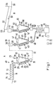
- the disposal device illustrated in FIG. 1 has a sewage sludge treatment device A, a plastic treatment device B, a mixing device C and a shaping device D.
- wet sludge with no more than 65% residual moisture is fed to a feed point 10. It is transported by a screw 11 through a tube 12 and preheated in the process. This is done with the help of a heating jacket 13, which is provided with an inflow line 14 for hot water and with a return line 15 for cooled water.
- the tube 12 is connected to a dryer 19 via a line 16.
- This has a container 20, from the interior 21 of which a suction line 23 leads to a vacuum pump.
- the interior can therefore be placed under negative pressure.
- the filling quantity 24 in the container 20 is heated by a heating device 25 in the form of a heating jacket, which has a steam feed line 26 at the top and a condensate drain 27 at the bottom.
- a mixing device 28 in the form of a screw 29 is provided, which is arranged near the cone wall of the container 20 and rotates about its axis 30.
- the axis 30 is in turn rotatable about the central axis of the collecting container 20.
- the material is evenly spherically deformed to form granules with a smooth, firm surface and a grain size of approximately 2 mm to 3 mm.
- This granulate is fed in batches or continuously via a solids lock 31, for example in the form of a cellular wheel lock, to a separator 38, preferably a cyclone separator, which separates the solids, including the dust, from the gases to be discharged via a line 39 .
- a separator 38 preferably a cyclone separator, which separates the solids, including the dust, from the gases to be discharged via a line 39 .
- the components penetrated by the sewage sludge in front of the separator 38 therefore form a sewage sludge drying device A1.
- the solids outlet of the separator 38 is connected via a lock 40 in the form of a cellular wheel lock to the input 41 of a converter 42, in which the chemically bound water and all other volatile constituents are expelled and the remaining organic constituents are converted into coal.
- the converter 42 is provided with a heating device 43 in the form of a hot gas channel, which is guided in a spiral around the container and to which hot combustion gases are fed via a line 44 such that the filling material 45 inside the converter is at least 200 ° C., preferably 380 ° to 400 ° C, heated.
- a mixing device 46 is provided which corresponds to that of the dryer 19. Water vapor and gaseous reaction products are sucked off via a line 47.
- the material thus dried and converted is in powder form and is fed to an outlet 49 for the powder via a lock 48 in the form of a cellular wheel lock.
- the composition of the powder depends on the area from which the sewage sludge is obtained. In urban areas, the proportion of minerals predominating from streets, marketplaces and the like predominates. results. Coal, for example, is represented by less than 30%.
- the plastic treatment device B has a feed point 50 which is loaded with plastic parts.
- An only indicated conveyor 51 for example as in a loading wagon in agriculture, conveys the plastic through a drying device 52 in the form of a channel through which hot air is blown, which is supplied via a line 53 and discharged via a line 54. In this way the surface of the plastic is dried.
- the plastic then falls into a comminution device 55, for example a chopping device.
- a comminution device 55 for example a chopping device.
- the now small plastic parts are pressed together by means of a screw conveyor 56 and transported into the container 57 of a melting device 58.
- This in turn has a heating device 59 in the form of a hot gas duct which is spirally guided around the container and to which combustion gases are supplied via a feed line 60.
- the container content 61 is thereby heated to a temperature of at least 250 ° C.
- a mixing device 62 which can be constructed similarly to the vacuum dryer 19 and the converter 42.
- thermoplastic is to be made plastic and flowable without volatile components being expelled to a significant extent.
- a higher temperature for example 500 ° to 600 ° C, however, the volatile constituents are largely removed from the plastic; they can be suctioned off via a line 63.
- This flowable mass can be taken off at an outlet 65 of the lock 64 arranged below, for example in the form of a cellular wheel or a screw.
- the outlet 49 for the sewage sludge powder and the outlet 65 for the flowable mass are connected to the mixing device C via lines 66 and 67.
- the mixing is carried out by means of a fine screw conveyor 68 which is supplied with flowable plastic and powder near one end, the mixture being removed at the other end.
- this screw conveyor also serves as an exit lock for the converter 42 and / or the melting device 58.
- extruded profiles or moldings consist of solidified plastic with an addition of sewage sludge powder, the powder being able to make up at least 30%, preferably up to 50%, of the total volume. If the plastic parts were not pre-sorted and therefore also contained types of plastic that could not be melted, the mixture may still have chopped parts of this plastic, which is permissible for most applications of the shaped bodies formed in this way.
- the moldings formed in this way have a smooth surface, but can also be made non-slip by roughening.
- the components of the mixture have a high temperature due to their previous treatment and therefore do not require any additional heating for mixing and shaping. It is recommended here that the connection between melting device 58 and mixing device C is short, while the powder can also be transported via a longer line 66. As a result of the addition of powder, the mixture has a higher viscosity than the flowable plastic. This is advantageous if, in the subsequent molding process, for example in extrusion, no flowable, but only a plastic material is required. However, if the consistency of the mixture is not sufficient for the molding process, a cooling device or a heating device can also be used in the molding device D. be provided. It is also possible to feed the sewage sludge powder to the mixing device after it has been stored temporarily. The cold powder lowers the mixture temperature by 30 ° to 40 ° C, so that separate cooling is often not necessary.
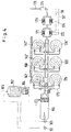
- a feed container 110 is supplied with sewage sludge 112 by a delivery vehicle 111, which has already passed through a filter chamber press and has only a residual moisture of 65%.
- This sewage sludge is distributed evenly over three containers 114, 114 ', 114' 'of a drying device 115 via a screw conveyor 113.
- the containers each have a heating jacket 116, which is supplied via a line 117 with hot thermal oil, which is discharged via a line 118. The heating can also be done with hot water or steam.
- the heating jacket 116 is surrounded by a heat insulation layer 119.
- the containers are connected to a vacuum system 121 via a suction line 120. Therefore, moisture is intensively removed from the sewage sludge.
- Drying can be supported by a mixing device which corresponds to the mixing device 28 in the main patent.
- the granulate formed in this way is fed via a conveyor 122 into a buffer container 123 and can be passed on via its delivery conveyor 124 via a delivery path 125.
- the exit conveyor is shown as a screw; but it can also be done in other ways, e.g. pneumatic, work.
- the delivery path consists of a fixed pipe connection, but can also be formed by transport with delivery vehicles. This is especially true in the event that several communities or users come together.
- the dried granulate passes into a converter 126.
- This consists of a conical container 127 with a heating jacket 128, to which hot gases are fed via a line 129, while the exhaust gases are discharged via a line 130.
- a mixing device 131 can be provided which corresponds to the mixing device 46 of the main pattern.
- the top of the container 127 is connected to a vacuum system 133 via a suction line 132.
- the oil, chemically bound water and all other volatile constituents contained therein are extracted from the dried granulate under vacuum, and the remaining organic constituents are converted into coal.
- a powder is formed which is fed into a buffer container 135 by means of a conveyor 134.
- a feed container 136 is provided for the plastic treatment, to which plastic waste 137 is fed from a delivery vehicle 138. This waste is transported by a conveyor 137 through a preheating tunnel 138 where it is dried.
- a press 139 follows, with which the plastic is pressed together before it reaches a comminution device 140, for example a shredder. The plastic chips are collected in a plastic buffer container 141.
- a combined melting and mixing device 142 has a conical container 143 which is provided with a heating jacket 144. This is fed with hot gases via a line 145. The exhaust gases are discharged via a line 146.
- a mixing device 147 is provided which corresponds to the mixing device 62 of the main patent.
- the heating jacket 144 is surrounded by a heat insulation layer 148.
- Plastic chips which are fed by means of a conveying device 149 via a pipeline inlet 150, and the powder remaining from the sewage sludge can be fed into the container 143 by means of a conveying device 151 via a pipeline inlet 152. If necessary, a further waste material, in particular raw gypsum in powder form, can be mixed with the sewage sludge powder supplied by the conveying device 151 through a feed channel 151a and fed to the melting tank 143 via the pipeline line entrance 152.
- the plastic is expediently first introduced and melted in the absence of air. Gases that are still formed in the process are conducted via a suction line 153 to a vacuum system 154. Powder is then gradually added towards the end of the melting process until a uniform mixture has resulted.
- This powder additive consists solely of the powder obtained from sewage sludge, which is supplied by means of the conveyor device 151, or a mixture of this powder and a further waste powder, in particular raw gypsum, which is supplied via the feed channel 151a.
- the vacuum system 154 can be switched off during this mixing process.
- a molding press 155 which, after opening the outlet 156 provided with a slide, is supplied with a flowable mixture.
- the end product 158 can be removed via a conveyor 157.
- the plastic press can be operated at a pressure of, for example, 40 to 60 bar.
- a system 159 containing nitrogen under pressure can be connected to the upper part of the container 143 by means of a changeover valve 160 instead of the vacuum system 154.
- the pressure supports the discharge of the mixture from the container.
- the inert property prevents unwanted reactions. In particular, oxygen is excluded, namely during melting and mixing because of the vacuum system 154 and during emptying of the container 143 because of the nitrogen system 159.
- the heating system in FIG. 4 has a gas burner 161, which is fed from a container 162 for combustible gases, and an oil burner 163, which is fed from an oil container 164.
- An arrow 165 schematically indicates that the flammable constituents of the volatile substances are collected in these containers, which get into the vacuum system 133 and 154, condensation levels and the like. are not shown.
- Another burner, not shown, can be fed with coal powder which is obtained by treating the powder originating from the sewage sludge, which partly consists of coal and partly of minerals, by means of an air classifier.
- the burners are assigned to a boiler 166, the combustion gases or hot gases of which are passed via a line 169 to three converters 126, 126 ', 126''and three combined melting and mixing devices 142, 142', 142 ''.
- the hot gases emerging from these pass through pipes 170 to four further heat exchangers, namely the heat exchanger 171 for steam, the heat exchanger 172 for thermal oil, the heat exchanger 173 for hot water and the heat exchanger 174 for combustion air to be preheated.
- a flue gas filter 175 and an exhaust air duct 176 follow, in which post-combustion for unused gases can be provided.
- the converters 126 and the melting and mixing device 142 as well as the drying devices 114 are provided in triplicate. With usual dimensions, an amount of 10 tons of plastic scrap and 10 m3 of sewage sludge per hour can be processed in this way. About 10 l of oil can be obtained from one cubic meter of sewage sludge, which is sufficient to maintain heating operation.
- the melting and mixing device 142 is located immediately above the molding device, the mixture has a high flowability. It can therefore be processed without difficulty with a compression of, for example, 60 bar by injection molding.
- Moldings in the form of paving stones have been successfully produced in the manner described, which consist of 40 to 60% plastic, 30 to 40% sewage sludge and 0 to 20% gypsum.
- Examples are: 60% plastic / 40% sewage sludge or 40% plastic / 40% sewage sludge / 20% gypsum or 50% plastic / 40% sewage sludge / 10% gypsum or 50% plastic / 30% sewage sludge / 20% gypsum.
- the plastic as a binder
- the sewage sludge powder as a filler
- the gypsum as a hardener.
Applications Claiming Priority (4)
| Application Number | Priority Date | Filing Date | Title |
|---|---|---|---|
| DE4231793A DE4231793C1 (de) | 1992-09-23 | 1992-09-23 | Verfahren und Vorrichtung zum Entsorgen von Abfallstoffen |
| DE4231793 | 1992-09-23 | ||
| DE4241977A DE4241977A1 (de) | 1992-09-23 | 1992-12-12 | Verfahren und Vorrichtung zum Entsorgen von Abfallstoffen sowie Extrusions- oder Formteil |
| DE4241977 | 1992-12-12 |
Publications (1)
| Publication Number | Publication Date |
|---|---|
| EP0589367A1 true EP0589367A1 (fr) | 1994-03-30 |
Family
ID=25918768
Family Applications (1)
| Application Number | Title | Priority Date | Filing Date |
|---|---|---|---|
| EP93115003A Withdrawn EP0589367A1 (fr) | 1992-09-23 | 1993-09-17 | Procédé et installation d'élimination de déchets ainsi que des pièces extrudées ou moulées |
Country Status (2)
| Country | Link |
|---|---|
| EP (1) | EP0589367A1 (fr) |
| DE (1) | DE4241977A1 (fr) |
Cited By (5)
| Publication number | Priority date | Publication date | Assignee | Title |
|---|---|---|---|---|
| EP0635346A1 (fr) * | 1993-07-08 | 1995-01-25 | WILLY KLAUSMANN, Inh. Hans Klausmann, Betonsteinwerk, Strassenbaustoffe, Güternahverkehr | Procédé pour la réutilisation des déchets plastiques |
| DE19503694A1 (de) * | 1995-02-04 | 1996-08-08 | Christian F Duerselen | Verwertungsmethode für Tetrapaks |
| WO1999020717A1 (fr) * | 1997-10-21 | 1999-04-29 | Zargham Niazi | Procede de production d'un corps combustible et dispositif correspondant |
| EP1201325A1 (fr) * | 2000-10-27 | 2002-05-02 | Sony Corporation | Additif pour résine, résine contenant de l'additif et son procédé de production |
| WO2011026642A1 (fr) * | 2009-09-04 | 2011-03-10 | Dieffenbacher Gmbh + Co. Kg | Dispositif et installation pour la fabrication de pastilles à partir de biomasse dans une presse à pastiller en vue de l'utilisation comme combustible dans des foyers |
Citations (10)
| Publication number | Priority date | Publication date | Assignee | Title |
|---|---|---|---|---|
| US4161825A (en) * | 1977-03-08 | 1979-07-24 | Uop Inc. | Plasticized organic waste |
| JPS5695397A (en) * | 1979-11-27 | 1981-08-01 | Shinya Watanabe | Production of hard object utilizing waste sludge and hard object thereof |
| JPS56116795A (en) * | 1980-02-21 | 1981-09-12 | Daiichi Nenryo Kogyo Kk | Manufacture of solid fuel using waste plastic |
| FR2575943A1 (fr) * | 1985-01-11 | 1986-07-18 | Jgc Corp | Procede de compactage et de solidification de dechets solides, appareil pour mettre en oeuvre ce procede et installation d'elimination de ces dechets |
| EP0383227A1 (fr) * | 1989-02-13 | 1990-08-22 | Wilfried Schraufstetter | Procédé pour lier des déchets particulaires comme de la poussière, déchets de métaux, fibres, déchets de papier en matière solide |
| EP0383229A1 (fr) * | 1989-02-13 | 1990-08-22 | Wilfried Schraufstetter | Préparation de boues contenant du fer pour le traitement ultérieur |
| US5035189A (en) * | 1990-08-03 | 1991-07-30 | Lunsford T J | Refuse recycling system |
| JPH0452303A (ja) * | 1990-06-20 | 1992-02-20 | Ryoko Sangyo Kk | 粒状廃棄物を利用した防滑性建材及び土木材 |
| JPH04126582A (ja) * | 1990-09-14 | 1992-04-27 | Tochigi Kaken Kogyo Kk | アルミスラッジの固化成形方法とその成形体 |
| JPH04190899A (ja) * | 1990-02-14 | 1992-07-09 | Ryoko Sangyo Kk | 汚泥成分を利用した成型品の製造法 |
-
1992
- 1992-12-12 DE DE4241977A patent/DE4241977A1/de not_active Ceased
-
1993
- 1993-09-17 EP EP93115003A patent/EP0589367A1/fr not_active Withdrawn
Patent Citations (10)
| Publication number | Priority date | Publication date | Assignee | Title |
|---|---|---|---|---|
| US4161825A (en) * | 1977-03-08 | 1979-07-24 | Uop Inc. | Plasticized organic waste |
| JPS5695397A (en) * | 1979-11-27 | 1981-08-01 | Shinya Watanabe | Production of hard object utilizing waste sludge and hard object thereof |
| JPS56116795A (en) * | 1980-02-21 | 1981-09-12 | Daiichi Nenryo Kogyo Kk | Manufacture of solid fuel using waste plastic |
| FR2575943A1 (fr) * | 1985-01-11 | 1986-07-18 | Jgc Corp | Procede de compactage et de solidification de dechets solides, appareil pour mettre en oeuvre ce procede et installation d'elimination de ces dechets |
| EP0383227A1 (fr) * | 1989-02-13 | 1990-08-22 | Wilfried Schraufstetter | Procédé pour lier des déchets particulaires comme de la poussière, déchets de métaux, fibres, déchets de papier en matière solide |
| EP0383229A1 (fr) * | 1989-02-13 | 1990-08-22 | Wilfried Schraufstetter | Préparation de boues contenant du fer pour le traitement ultérieur |
| JPH04190899A (ja) * | 1990-02-14 | 1992-07-09 | Ryoko Sangyo Kk | 汚泥成分を利用した成型品の製造法 |
| JPH0452303A (ja) * | 1990-06-20 | 1992-02-20 | Ryoko Sangyo Kk | 粒状廃棄物を利用した防滑性建材及び土木材 |
| US5035189A (en) * | 1990-08-03 | 1991-07-30 | Lunsford T J | Refuse recycling system |
| JPH04126582A (ja) * | 1990-09-14 | 1992-04-27 | Tochigi Kaken Kogyo Kk | アルミスラッジの固化成形方法とその成形体 |
Non-Patent Citations (5)
| Title |
|---|
| PATENT ABSTRACTS OF JAPAN vol. 16, no. 239 (M - 1258) 20 June 1990 (1990-06-20) * |
| PATENT ABSTRACTS OF JAPAN vol. 16, no. 387 (C - 975) 18 August 1992 (1992-08-18) * |
| PATENT ABSTRACTS OF JAPAN vol. 16, no. 512 (C - 998) 22 October 1992 (1992-10-22) * |
| PATENT ABSTRACTS OF JAPAN vol. 5, no. 164 (C - 76) 21 October 1981 (1981-10-21) * |
| PATENT ABSTRACTS OF JAPAN vol. 5, no. 195 (C - 83) 11 December 1981 (1981-12-11) * |
Cited By (7)
| Publication number | Priority date | Publication date | Assignee | Title |
|---|---|---|---|---|
| EP0635346A1 (fr) * | 1993-07-08 | 1995-01-25 | WILLY KLAUSMANN, Inh. Hans Klausmann, Betonsteinwerk, Strassenbaustoffe, Güternahverkehr | Procédé pour la réutilisation des déchets plastiques |
| DE19503694A1 (de) * | 1995-02-04 | 1996-08-08 | Christian F Duerselen | Verwertungsmethode für Tetrapaks |
| WO1999020717A1 (fr) * | 1997-10-21 | 1999-04-29 | Zargham Niazi | Procede de production d'un corps combustible et dispositif correspondant |
| EP1201325A1 (fr) * | 2000-10-27 | 2002-05-02 | Sony Corporation | Additif pour résine, résine contenant de l'additif et son procédé de production |
| US6720365B2 (en) | 2000-10-27 | 2004-04-13 | Sony Corporation | Additive for resin, additive-containing resin, and method for producing the same |
| WO2011026642A1 (fr) * | 2009-09-04 | 2011-03-10 | Dieffenbacher Gmbh + Co. Kg | Dispositif et installation pour la fabrication de pastilles à partir de biomasse dans une presse à pastiller en vue de l'utilisation comme combustible dans des foyers |
| CN102625826A (zh) * | 2009-09-04 | 2012-08-01 | 迪芬巴赫机械工程有限公司 | 用于在压粒机中由生物质生产颗粒以用作壁炉中的燃料的方法和设备 |
Also Published As
| Publication number | Publication date |
|---|---|
| DE4241977A1 (de) | 1994-06-16 |
Similar Documents
| Publication | Publication Date | Title |
|---|---|---|
| DE2520152A1 (de) | Verfahren und anlage zur trockenen destillation von organischem material | |
| EP0383227B1 (fr) | Procédé pour lier des déchets particulaires comme de la poussière, déchets de métaux, fibres, déchets de papier en matière solide | |
| DE2638017A1 (de) | Vorrichtung zum beseitigen fester abfallstoffe, insbesondere muell, und zum rueckgewinnen eines brennstoffes aus dem abfall | |
| EP0543133B1 (fr) | Procédé et appareillage pour le traitement de la boue d'épuration épaissie | |
| WO2000071477A1 (fr) | Procede et installation de pretraitement, de granulation et de sechage de boues industrielles en vue de leur recyclage | |
| DE19909328B4 (de) | Abfallverwertungsverfahren | |
| DE4313977A1 (de) | Verfahren zur Wiederverwertung von Kunststoff-Hausmüllabfällen | |
| EP0589367A1 (fr) | Procédé et installation d'élimination de déchets ainsi que des pièces extrudées ou moulées | |
| EP0621885B1 (fr) | Procede pour le retraitement de dechets en matiere plastique | |
| DE3501139A1 (de) | Formkoerper aus kunststoffabfaellen und verfahren zu seiner herstellung | |
| DE3037714A1 (de) | Anlage zur muellaufbereitung und rueckgewinnung | |
| DE4231793C1 (de) | Verfahren und Vorrichtung zum Entsorgen von Abfallstoffen | |
| WO2020030729A1 (fr) | Dispositif et système de préparation d'eau résiduelle de béton | |
| DE102005017334A1 (de) | Verfahren und Vorrichtung zur Entsorgung von Abfall | |
| DE4000510C2 (de) | Verfahren und Anlage zum Kompostieren von Müll | |
| EP0647697B1 (fr) | Procédé et installation pour le traitement d'ordures | |
| DE2229535A1 (de) | Verfahren und vorrichtung zum formpressen von kunststoffen | |
| DE102006036661A1 (de) | Verfahren zur thermischen Verwertung von Kunststoffabfällen aus Industrie und Haushalt | |
| DE2656117A1 (de) | Verfahren und vorrichtung zum regenerieren von asphaltabfaellen | |
| DE3603009C2 (de) | Verfahren und Vorrichtung zur Verarbeitung und Wiederverwendung von Kunststoffabfällen | |
| CH610235A5 (en) | Casting and process for the production thereof | |
| DE19708458C2 (de) | Verfahren zur Aufarbeitung von Spuckstoffen und die Verwendung des nach dem Verfahren hergestellten Produktes | |
| DE102011052015A1 (de) | Verfahren zur Herstellung dreidimensionaler Gegenstände aus Recyclat-Kunststoffmassen, Verwendung der dreidimensionalen Gegenstände und nach dem Verfahren hergestellte dreidimensionale Gegenstände | |
| CH664149A5 (en) | Humus concentrate mfr. - from domestic refuse by pre:sorting, mixing with finished compost, crushing and compacting before rotting | |
| DE2455987A1 (de) | Verfahren einer kunststoff-regenerationsanlage (rueckgewinnung) fuer kunststoffabfaelle jeglicher art |
Legal Events
| Date | Code | Title | Description |
|---|---|---|---|
| PUAI | Public reference made under article 153(3) epc to a published international application that has entered the european phase |
Free format text: ORIGINAL CODE: 0009012 |
|
| AK | Designated contracting states |
Kind code of ref document: A1 Designated state(s): AT BE CH DK FR GB IE IT LI NL SE |
|
| 17P | Request for examination filed |
Effective date: 19940702 |
|
| 19U | Interruption of proceedings before grant |
Effective date: 19950313 |
|
| 19W | Proceedings resumed before grant after interruption of proceedings |
Effective date: 19961202 |
|
| RAP1 | Party data changed (applicant data changed or rights of an application transferred) |
Owner name: BOLZ, GISELA |
|
| STAA | Information on the status of an ep patent application or granted ep patent |
Free format text: STATUS: THE APPLICATION HAS BEEN WITHDRAWN |
|
| 18W | Application withdrawn |
Withdrawal date: 19961018 |