EP0589178A1 - Shape of the combustion chamber for air compressing, self-ignited engines - Google Patents
Shape of the combustion chamber for air compressing, self-ignited engines Download PDFInfo
- Publication number
- EP0589178A1 EP0589178A1 EP93112041A EP93112041A EP0589178A1 EP 0589178 A1 EP0589178 A1 EP 0589178A1 EP 93112041 A EP93112041 A EP 93112041A EP 93112041 A EP93112041 A EP 93112041A EP 0589178 A1 EP0589178 A1 EP 0589178A1
- Authority
- EP
- European Patent Office
- Prior art keywords
- combustion chamber
- cylinder
- cylinder head
- injection nozzle
- curvature
- Prior art date
- Legal status (The legal status is an assumption and is not a legal conclusion. Google has not performed a legal analysis and makes no representation as to the accuracy of the status listed.)
- Granted
Links
Images


Classifications
-
- F—MECHANICAL ENGINEERING; LIGHTING; HEATING; WEAPONS; BLASTING
- F02—COMBUSTION ENGINES; HOT-GAS OR COMBUSTION-PRODUCT ENGINE PLANTS
- F02B—INTERNAL-COMBUSTION PISTON ENGINES; COMBUSTION ENGINES IN GENERAL
- F02B23/00—Other engines characterised by special shape or construction of combustion chambers to improve operation
- F02B23/02—Other engines characterised by special shape or construction of combustion chambers to improve operation with compression ignition
- F02B23/06—Other engines characterised by special shape or construction of combustion chambers to improve operation with compression ignition the combustion space being arranged in working piston
- F02B23/0645—Details related to the fuel injector or the fuel spray
- F02B23/0669—Details related to the fuel injector or the fuel spray having multiple fuel spray jets per injector nozzle
-
- F—MECHANICAL ENGINEERING; LIGHTING; HEATING; WEAPONS; BLASTING
- F02—COMBUSTION ENGINES; HOT-GAS OR COMBUSTION-PRODUCT ENGINE PLANTS
- F02B—INTERNAL-COMBUSTION PISTON ENGINES; COMBUSTION ENGINES IN GENERAL
- F02B23/00—Other engines characterised by special shape or construction of combustion chambers to improve operation
- F02B23/02—Other engines characterised by special shape or construction of combustion chambers to improve operation with compression ignition
- F02B23/06—Other engines characterised by special shape or construction of combustion chambers to improve operation with compression ignition the combustion space being arranged in working piston
- F02B23/0696—W-piston bowl, i.e. the combustion space having a central projection pointing towards the cylinder head and the surrounding wall being inclined towards the cylinder wall
-
- F—MECHANICAL ENGINEERING; LIGHTING; HEATING; WEAPONS; BLASTING
- F02—COMBUSTION ENGINES; HOT-GAS OR COMBUSTION-PRODUCT ENGINE PLANTS
- F02B—INTERNAL-COMBUSTION PISTON ENGINES; COMBUSTION ENGINES IN GENERAL
- F02B2275/00—Other engines, components or details, not provided for in other groups of this subclass
- F02B2275/14—Direct injection into combustion chamber
-
- F—MECHANICAL ENGINEERING; LIGHTING; HEATING; WEAPONS; BLASTING
- F02—COMBUSTION ENGINES; HOT-GAS OR COMBUSTION-PRODUCT ENGINE PLANTS
- F02B—INTERNAL-COMBUSTION PISTON ENGINES; COMBUSTION ENGINES IN GENERAL
- F02B23/00—Other engines characterised by special shape or construction of combustion chambers to improve operation
- F02B23/02—Other engines characterised by special shape or construction of combustion chambers to improve operation with compression ignition
- F02B23/06—Other engines characterised by special shape or construction of combustion chambers to improve operation with compression ignition the combustion space being arranged in working piston
- F02B23/0618—Other engines characterised by special shape or construction of combustion chambers to improve operation with compression ignition the combustion space being arranged in working piston having in-cylinder means to influence the charge motion
- F02B23/063—Other engines characterised by special shape or construction of combustion chambers to improve operation with compression ignition the combustion space being arranged in working piston having in-cylinder means to influence the charge motion the combustion space in the piston interacting fluid dynamically with the cylinder head, the injector body or the cylinder wall
-
- F—MECHANICAL ENGINEERING; LIGHTING; HEATING; WEAPONS; BLASTING
- F02—COMBUSTION ENGINES; HOT-GAS OR COMBUSTION-PRODUCT ENGINE PLANTS
- F02B—INTERNAL-COMBUSTION PISTON ENGINES; COMBUSTION ENGINES IN GENERAL
- F02B23/00—Other engines characterised by special shape or construction of combustion chambers to improve operation
- F02B23/02—Other engines characterised by special shape or construction of combustion chambers to improve operation with compression ignition
- F02B23/06—Other engines characterised by special shape or construction of combustion chambers to improve operation with compression ignition the combustion space being arranged in working piston
- F02B23/0678—Unconventional, complex or non-rotationally symmetrical shapes of the combustion space, e.g. flower like, having special shapes related to the orientation of the fuel spray jets
- F02B23/0684—Ring like bowl, e.g. toroidal
-
- F—MECHANICAL ENGINEERING; LIGHTING; HEATING; WEAPONS; BLASTING
- F02—COMBUSTION ENGINES; HOT-GAS OR COMBUSTION-PRODUCT ENGINE PLANTS
- F02B—INTERNAL-COMBUSTION PISTON ENGINES; COMBUSTION ENGINES IN GENERAL
- F02B23/00—Other engines characterised by special shape or construction of combustion chambers to improve operation
- F02B23/02—Other engines characterised by special shape or construction of combustion chambers to improve operation with compression ignition
- F02B23/06—Other engines characterised by special shape or construction of combustion chambers to improve operation with compression ignition the combustion space being arranged in working piston
- F02B23/0678—Unconventional, complex or non-rotationally symmetrical shapes of the combustion space, e.g. flower like, having special shapes related to the orientation of the fuel spray jets
- F02B23/069—Unconventional, complex or non-rotationally symmetrical shapes of the combustion space, e.g. flower like, having special shapes related to the orientation of the fuel spray jets characterised by its eccentricity from the cylinder axis
-
- F—MECHANICAL ENGINEERING; LIGHTING; HEATING; WEAPONS; BLASTING
- F02—COMBUSTION ENGINES; HOT-GAS OR COMBUSTION-PRODUCT ENGINE PLANTS
- F02B—INTERNAL-COMBUSTION PISTON ENGINES; COMBUSTION ENGINES IN GENERAL
- F02B3/00—Engines characterised by air compression and subsequent fuel addition
- F02B3/06—Engines characterised by air compression and subsequent fuel addition with compression ignition
-
- F—MECHANICAL ENGINEERING; LIGHTING; HEATING; WEAPONS; BLASTING
- F02—COMBUSTION ENGINES; HOT-GAS OR COMBUSTION-PRODUCT ENGINE PLANTS
- F02F—CYLINDERS, PISTONS OR CASINGS, FOR COMBUSTION ENGINES; ARRANGEMENTS OF SEALINGS IN COMBUSTION ENGINES
- F02F1/00—Cylinders; Cylinder heads
- F02F1/24—Cylinder heads
- F02F2001/244—Arrangement of valve stems in cylinder heads
- F02F2001/245—Arrangement of valve stems in cylinder heads the valve stems being orientated at an angle with the cylinder axis
- F02F2001/246—Arrangement of valve stems in cylinder heads the valve stems being orientated at an angle with the cylinder axis and orientated radially from the combustion chamber surface
-
- Y—GENERAL TAGGING OF NEW TECHNOLOGICAL DEVELOPMENTS; GENERAL TAGGING OF CROSS-SECTIONAL TECHNOLOGIES SPANNING OVER SEVERAL SECTIONS OF THE IPC; TECHNICAL SUBJECTS COVERED BY FORMER USPC CROSS-REFERENCE ART COLLECTIONS [XRACs] AND DIGESTS
- Y02—TECHNOLOGIES OR APPLICATIONS FOR MITIGATION OR ADAPTATION AGAINST CLIMATE CHANGE
- Y02T—CLIMATE CHANGE MITIGATION TECHNOLOGIES RELATED TO TRANSPORTATION
- Y02T10/00—Road transport of goods or passengers
- Y02T10/10—Internal combustion engine [ICE] based vehicles
- Y02T10/12—Improving ICE efficiencies
Definitions
- the invention relates to a combustion chamber shape according to the preamble of claim 1.
- the combustion chamber of direct-injection internal combustion engines is formed from the cylinder, the cylinder head and the piston crown.
- Various shapes have been developed to improve the boundary conditions for increasing the indicated efficiency, but they do not take sufficient account of optimal combustion in the sense of improving the exhaust gas quality.
- the invention is therefore based on the object, with a given piston diameter, to keep the free jet length of the injected fuel jet as large as possible and the same for all jets without fuel droplets coming into contact with the wall before the burnout.
- this object is achieved in cylinder heads with an intake and exhaust valve on the one hand by the characterizing features of claim 1.
- the fuel jets Due to the cylinder head designed as a spherical section and the conical shape of the piston head in connection with the centrally arranged injection nozzle, the fuel jets have the Possibility to cover a large free path without the fuel droplets being cooled by premature contact with one of the combustion chamber walls and no longer being optimally evaporated, mixed with air and able to burn out.
- the shape of the combustion chamber according to the invention thus makes a contribution to improving the exhaust gas quality.
- the space between the piston crown and the cylinder head is so small that the fanning out fuel jet would come into contact with the wall, which is avoided by radial depressions in the piston crown.
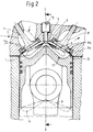
- the inclination of the surface 3a is chosen such that the fuel jets emanating from a multi-jet injection nozzle 13 do not touch the surface 3a of the piston head 3, nor the surfaces 10a, 10b of the intake or exhaust valve 7 or 8 or the cylinder head base 4.
- the holes of the injector 13 are evenly distributed on the circumference, so that each of the fuel jets finds the same boundary conditions.
- the piston is pulled up in the edge region as an apron 12.
- the distance from the apron 12 to the cylinder head base 4 is to be kept as small as possible in order to keep the harmful space small.
- FIG. 2 with an inlet duct arranged parallel to the cylinder axis is particularly suitable for two-stroke operation.
- the inlet and outlet valves 7, 8 are open in order to flush the combustion chamber 1.
- the UT position "x" of the piston is shown in dotted lines.
- Figure 3 shows in a longitudinal or cross-section III-III of Figure 4, the course of the cylinder head base 4 on the combustion chamber side when using four valves, that is, with two intake and two exhaust valves 7a, 7b and 8a, 8b.
- the cylinder head base 4 has in the plane spanned by an engine longitudinal axis and a cylinder axis a radius of curvature r2 with a center of curvature 6a, while in the plane spanned by the cylinder axis and perpendicular to the engine longitudinal axis, the radius of curvature is r3.
- the center of curvature is for r3 in point 6b.
- the different radii of curvature are necessary, since valves of neighboring cylinders would otherwise get in the way, as is illustrated in FIG. 4.
- the piston crown 3 follows the distance "a" shown in FIGS. 1 and 2 Course of the cylinder head base 4. For a constant distance from the cylinder axis, the distance "a" between surface 3a and cylinder head base 4 is always constant.
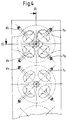
- FIG. 4 schematically shows a top view in the direction of the cylinder heads when using 4 valves (FIG. 3).
- Each cylinder head has the two intake and exhaust valves 7a, 7b and 8a, 8b, the axes of which are to be thought of as protruding from the plane of the drawing. So that the valves 7a, 7b and 8a, 8b of adjacent cylinders do not affect, the cylinder head base 4 has two continuously merging spherical sections with different curvatures r2 and r3 shown in FIG.
- the valves standing perpendicular to the locally resulting surfaces of the cylinder head base 4 thus have a suitable spatial position so that they do not affect one another.
- valve centers of the intake and exhaust valves 7a, 7b and 8a, 8b do not necessarily have to go through the center of the cylinder.
Abstract
Die Erfindung bezieht sich auf eine Brennraumform für luftverdichtende Brennkraftmaschinen. Das Ziel der Erfindung ist die optimale Verbrennung der eingespritzten Brennstoffmenge. Erfindungsgemäß wird dies dadurch erreicht, daß der Brennraum derart gestaltet wird, daß die von der in der Zylinderachse gelegenen Mehrstrahl-Einspritzdüse (13) ausgehenden Brennstoffstrahlen (9) keine Wandberührung erleiden. Zu diesem Zweck ist der Kolbenboden (3) kegelförmig gestaltet, wobei die Neigung der Kegelfläche so zu wählen ist, daß sich der Kolbenboden (3) der Form des auffächernden Brennstoffstrahles (9) anpaßt. Der Zylinderkopfboden (3) ist als Kugelabschnitt ausgebildet, ebenfalls mit dem Ziel, daß der Brennstoffstrahl (9) keine Wandberührung bekommt. Der kegelförmig gestaltete Kolbenboden (3) kann zudem noch radial verlaufende Mulden (11) aufweisen für den Fall, daß der Verbrennungsraum wegen eines hohen Verdichtungsverhältnisses sehr klein bemessen werden muß. Durch die Mulden (11) kann trotz geringen Abstandes zwischen Kolbenboden (3) und Zylinderkopfboden (4) eine Wandberührung des Brennstoffstrahles (9) und daraus resultierende, unvollständige Verbrennung vermieden werden. Durch die erfindungsgemäße Brennraumform lassen sich die verschärften Abgasnormen für Nutzfahrzeuge erfüllen. <IMAGE>The invention relates to a combustion chamber shape for air-compressing internal combustion engines. The aim of the invention is the optimal combustion of the amount of fuel injected. According to the invention, this is achieved by designing the combustion chamber in such a way that the fuel jets (9) emanating from the multi-jet injection nozzle (13) located in the cylinder axis do not come into contact with the wall. For this purpose the piston crown (3) is conical, the inclination of the conical surface should be selected so that the piston crown (3) adapts to the shape of the fanning out fuel jet (9). The cylinder head base (3) is designed as a spherical section, also with the aim that the fuel jet (9) does not come into contact with the wall. The conical piston crown (3) can also have radial troughs (11) in the event that the combustion chamber has to be dimensioned very small because of a high compression ratio. The troughs (11), despite the small distance between the piston crown (3) and the cylinder head crown (4), prevent the fuel jet (9) from touching the wall and the resulting incomplete combustion. The stricter exhaust gas standards for commercial vehicles can be met by the shape of the combustion chamber according to the invention. <IMAGE>
Description
Die Erfindung bezieht sich auf eine Brennraumform gemäß dem Gattungsbegriff des Patentanspruches 1.The invention relates to a combustion chamber shape according to the preamble of
Der Brennraum direkteinspritzender Brennkraftmaschinen wird aus dem Zylinder, dem Zylinderkopf und dem Kolbenboden gebildet. Zur Verbesserung der Randbedingungen für die Anhebung des indizierten Wirkungsgrades wurden diverse Formgebungen entwickelt, die jedoch nicht ausreichend Rücksicht nehmen auf eine optimale Verbrennung im Sinne einer Verbesserung der Abgasqualität.The combustion chamber of direct-injection internal combustion engines is formed from the cylinder, the cylinder head and the piston crown. Various shapes have been developed to improve the boundary conditions for increasing the indicated efficiency, but they do not take sufficient account of optimal combustion in the sense of improving the exhaust gas quality.
Der Erfindung liegt daher die Aufgabe zugrunde, bei vorgegebenem Kolbendurchmesser die freie Strahllänge des eingespritzten Brennstoffstrahles möglichst groß und für alle Strahlen gleich zu halten, ohne daß Brennstofftröpfchen vor dem Ausbrand Wandberührung bekommen.The invention is therefore based on the object, with a given piston diameter, to keep the free jet length of the injected fuel jet as large as possible and the same for all jets without fuel droplets coming into contact with the wall before the burnout.
Erfindungsgemäß wird diese Aufgabe bei Zylinderköpfen mit einem Einlaß- und Auslaßventil einerseits durch die kennzeichnenden Merkmale des Patentanspruches 1 gelöst.According to the invention, this object is achieved in cylinder heads with an intake and exhaust valve on the one hand by the characterizing features of
Durch den als Kugelabschnitt ausgebildeten Zylinderkopf und die kegelige Form des Kolbenbodens in Zusammenhang mit der mittig angeordneten Einspritzdüse haben die Brennstoffstrahlen die Möglichkeit eine große freie Weglänge zurückzulegen, ohne daß die Brennstofftröpfchen durch vorzeitige Berührung mit einer der Brennraumwände abgekühlt werden und nicht mehr optimal verdampft, mit Luft vermischt und ausbrennen können. Durch die erfindungsgemäße Brennraumform wird also ein Beitrag zur Verbesserung der Abgasqualität geleistet.Due to the cylinder head designed as a spherical section and the conical shape of the piston head in connection with the centrally arranged injection nozzle, the fuel jets have the Possibility to cover a large free path without the fuel droplets being cooled by premature contact with one of the combustion chamber walls and no longer being optimally evaporated, mixed with air and able to burn out. The shape of the combustion chamber according to the invention thus makes a contribution to improving the exhaust gas quality.
Bei Verwendung eines Zylinderkopfes mit je zwei Einlaß- und Auslaßventilen wird diese Aufgabe andererseits durch die kennzeichnenden Merkmale des Patentanspruches 2 gelöst.When using a cylinder head with two intake and exhaust valves, this object is achieved on the other hand by the characterizing features of
Durch die Anwendung von vier Ventilen je Zylinderkopf ist es notwendig, den Zylinderkopfboden aus zwei verschiedenen, stetig ineinander übergehenden Kugelabschnitten zusammenzusetzen, da sich die schräg angeordneten Ventile benachbarter Zylinder gegenseitig stören würden.By using four valves per cylinder head, it is necessary to assemble the cylinder head base from two different spherical sections that continuously merge into each other, since the diagonally arranged valves of adjacent cylinders would interfere with each other.
Eine vorteilhafte Weiterbildung der erfindungsgemäßen Brennraumform kann Unteranspruch 3 entnommen werden.An advantageous further development of the combustion chamber shape according to the invention can be found in
Bei Brennkraftmaschinen mit hohem Verdichtungsverhältnis wird der Raum zwischen Kolbenboden und Zylinderkopf so klein, daß der sich auffächernde Brennstoffstrahl an seinem Umfang Wandberührung bekommen würde, was durch radiale Mulden im Kolbenboden vermieden wird.In internal combustion engines with a high compression ratio, the space between the piston crown and the cylinder head is so small that the fanning out fuel jet would come into contact with the wall, which is avoided by radial depressions in the piston crown.
Ausführungsbeispiele der erfindungsgemäßen Brennraumform können den Zeichnungen entnommen werden. Es zeigt:
Figur 1- einen Schnitt I-I aus
Figur 2 zur Darstellung der Kugelabschnittsform des Zylinderkopfes Figur 2- einen Schnitt II-II durch einen Brennraum bei Verwendung von einem Einlaß- und einem Auslaßventil
Figur 3- einen Längs- bzw. Querschnitt III-III aus Figur 4 durch einen Brennraum bei Verwendung von zwei Einlaß- und zwei Auslaßventilen
- Figur 4
- Draufsicht auf eine mehrzylindrige Brennkraftmaschine mit vier Ventilen je Zylinder
- Figure 1
- a section II of Figure 2 to show the spherical section shape of the cylinder head
- Figure 2
- a section II-II through a combustion chamber when using an inlet and an exhaust valve
- Figure 3
- a longitudinal or cross section III-III of Figure 4 through a combustion chamber when using two inlet and two exhaust valves
- Figure 4
- Top view of a multi-cylinder internal combustion engine with four valves per cylinder
FIG. 1 schematically shows the contour profile of a
Die Neigung der Fläche 3a wird derart gewählt, daß die von einer mehrstrahligen Einspritzdüse 13 ausgehenden Brennstoffstrahlen weder die Fläche 3a des Kolbenbodens 3, noch die Flächen 10a, 10b des Einlaß- bzw. Auslaßventils 7 bzw. 8 oder den Zylinderkopfboden 4 berühren. Die Bohrungen der Einspritzdüse 13 seien am Umfang gleichmäßig verteilt angebracht, so daß jeder der Brennstoffstrahlen gleiche Randbedingungen vorfindet.The inclination of the
Bei einem hohen Verdichtungsverhältnis wird der Abstand zwischen dem Zylinderkopfboden 4 und der Fläche 3a so gering, daß die Brennstoffstrahlen 9 in ihrem Randbereich diese Teile berühren können, was zu unverbrannten Brennstoff-Bestandteilen im Abgas führen kann. Es wird deshalb entsprechend der Ausführung nach Figur 2 vorgeschlagen, daß in den Kolbenboden 3 Mulden 11 eingearbeitet werden. Diese Mulden 11 sind bei hohem Verdichtungsverhältnis ebenso wie der Verlauf der Fläche 3a im Falle eines niedrigen Verdichtungsverhältnis dem Verlauf der auffächernden Brennstoffstrahlen 9 angepaßt.With a high compression ratio, the distance between the cylinder head base 4 and the
Zum Schutz der Zylinderwand und zur Verringerung des Schadraumes ist der Kolben in seinem Randbereich als Schürze 12 hochgezogen. Der Abstand von Schürze 12 zum Zylinderkopfboden 4 ist so klein als möglich zu halten, um den schädlichen Raum klein zu halten.To protect the cylinder wall and to reduce the damage space, the piston is pulled up in the edge region as an
Die Ausführung nach Figur 2 mit parallel zur Zylinderachse angeordnetem Einlaßkanal ist besonders für Zweitakt-Betrieb geeignet. Wenn sich der Kolben im Zweitakt-Betrieb im Bereich der UT-Stellung befindet sind Ein- und Auslaßventil 7, 8 geöffnet, um die Spülung des Brennraumes 1 durchzuführen. Die UT-Stellung "x" des Kolbens ist punktstrichliert dargetellt.The embodiment according to FIG. 2 with an inlet duct arranged parallel to the cylinder axis is particularly suitable for two-stroke operation. When the piston is in two-stroke mode in the UT position, the inlet and
Figur 3 zeigt in einem Längs- bzw. Querschnitt III-III aus Figur 4 den Verlauf des Zylinderkopfbodens 4 auf der Brennraumseite bei Anwendung von vier Ventilen, also bei zwei Einlaß- und zwei Auslaßventilen 7a, 7b bzw. 8a, 8b. Der Zylinderkopfboden 4 weist in der Ebene die von einer Motorlängsachse und einer Zylinderachse aufgespannt wird einen Krümmungsradius r₂ mit einem Krümmungsmittelpunkt 6a auf, während in der Ebene die von der Zylinderachse und rechtwinklig zur Motorlängsachse aufgespannt wird der Krümmungsradius r₃ beträgt. Der Krümmungsmittelpunkt liegt für r₃ in Punkt 6b. Die unterschiedlichen Krümmungsradien werden erforderlich, da sich sonst Ventile benachbarter Zylinder im Wege stehen, wie dies in Figur 4 veranschaulicht wird. Der Kolbenboden 3 folgt bezüglich Abstand "a" dem in den Figuren 1 bzw. 2 dargestellten Verlauf des Zylinderkopfbodens 4. Für einen konstanten Abstand von der Zylinderachse ist der Abstand "a" zwischen Fläche 3a und Zylinderkopfboden 4 stets gleichbleibend.Figure 3 shows in a longitudinal or cross-section III-III of Figure 4, the course of the cylinder head base 4 on the combustion chamber side when using four valves, that is, with two intake and two
Figur 4 zeigt schematisch eine Draufsicht in Richtung auf die Zylinderköpfe bei Anwendung von 4 Ventilen (Figur 3). Jeder Zylinderkopf weist die zwei Einlaß- und Auslaßventile 7a, 7b bzw. 8a, 8b auf, deren Achsen aus der Zeichenebene herausragend zu denken sind. Damit sich die Ventile 7a, 7b und 8a, 8b benachbarter Zylinder nicht tangieren weist der Zylinderkopfboden 4 zwei stetig ineinander übergehende Kugelabschnitte mit aus Figur 3 ersichtlichen unterschiedlichen Krümmungen r₂ und r₃ auf. Die jeweils lotrecht auf den örtlich sich ergebenden Flächen des Zylinderkopfbodens 4 (Figur 3) stehenden Ventile weisen damit eine geeignete räumliche Lage auf, so daß sie sich nicht tangieren.FIG. 4 schematically shows a top view in the direction of the cylinder heads when using 4 valves (FIG. 3). Each cylinder head has the two intake and
Die Ventilmitten der Einlaß- und Auslaßventile 7a, 7b bzw. 8a, 8b müssen dabei nicht unbedingt durch die Zylindermitte gehen.The valve centers of the intake and
Claims (4)
Applications Claiming Priority (2)
| Application Number | Priority Date | Filing Date | Title |
|---|---|---|---|
| DE4228518A DE4228518A1 (en) | 1992-08-27 | 1992-08-27 | Combustion chamber shape for air-compressing, self-igniting internal combustion engines |
| DE4228518 | 1992-08-27 |
Publications (2)
| Publication Number | Publication Date |
|---|---|
| EP0589178A1 true EP0589178A1 (en) | 1994-03-30 |
| EP0589178B1 EP0589178B1 (en) | 1996-03-06 |
Family
ID=6466572
Family Applications (1)
| Application Number | Title | Priority Date | Filing Date |
|---|---|---|---|
| EP93112041A Expired - Lifetime EP0589178B1 (en) | 1992-08-27 | 1993-07-28 | Shape of the combustion chamber for air compressing, self-ignited engines |
Country Status (4)
| Country | Link |
|---|---|
| US (1) | US5363820A (en) |
| EP (1) | EP0589178B1 (en) |
| JP (1) | JPH06185366A (en) |
| DE (2) | DE4228518A1 (en) |
Cited By (8)
| Publication number | Priority date | Publication date | Assignee | Title |
|---|---|---|---|---|
| EP0849448A1 (en) * | 1996-12-19 | 1998-06-24 | Cummins Engine Company, Inc. | Deep angle injection nozzle and piston having complementary combustion bowl |
| FR2818324A1 (en) | 2000-12-20 | 2002-06-21 | Inst Francais Du Petrole | Direct injection i.c. engine has injector spray angle of predetermined dimensions relative to cylinder diameter and piston position |
| FR2818325A1 (en) | 2001-07-30 | 2002-06-21 | Inst Francais Du Petrole | Direct injection i.c. engine has injector spray angle of predetermined dimensions relative to cylinder diameter and piston position |
| EP1217186A2 (en) | 2000-12-20 | 2002-06-26 | Institut Francais Du Petrole | Direct injection engine with small spray angle and methods of using such an engine |
| FR2827913A1 (en) | 2001-07-27 | 2003-01-31 | Inst Francais Du Petrole | METHOD FOR CONTROLLING THE INJECTION OF A FUEL FOR A DIRECT INJECTION INTERNAL COMBUSTION ENGINE |
| US6732703B2 (en) | 2002-06-11 | 2004-05-11 | Cummins Inc. | Internal combustion engine producing low emissions |
| US7210448B2 (en) | 2002-06-11 | 2007-05-01 | Cummins, Inc. | Internal combustion engine producing low emissions |
| US8677970B2 (en) | 2011-03-17 | 2014-03-25 | Cummins Intellectual Property, Inc. | Piston for internal combustion engine |
Families Citing this family (9)
| Publication number | Priority date | Publication date | Assignee | Title |
|---|---|---|---|---|
| DE19510053C2 (en) * | 1994-04-08 | 1997-09-04 | Ford Werke Ag | Multi-cylinder reciprocating internal combustion engine |
| CN1083528C (en) * | 1997-06-03 | 2002-04-24 | 日产自动车株式会社 | Piston for cylinder direct injection spark ignition internal combustion engine |
| US6318308B1 (en) * | 1998-11-16 | 2001-11-20 | General Electric Company | Increased compression ratio diesel engine assembly for retarded fuel injection timing |
| US6360709B1 (en) * | 1999-12-23 | 2002-03-26 | Daimlerchrysler Corporation | Piston top geometry for optimized combustion |
| WO2004059144A1 (en) * | 2002-12-26 | 2004-07-15 | Akulinin, Alexander | The working chamber of piston machine (variants) |
| FR2849901B1 (en) * | 2003-01-13 | 2005-03-11 | Renault Sa | CYLINDER FOR INTERNAL COMBUSTION ENGINE AND COMPRESSION IGNITION AND ENGINE COMPRISING SUCH A CYLINDER |
| DE102004004391A1 (en) * | 2004-01-29 | 2005-08-11 | Daimlerchrysler Ag | Direct injection internal combustion engine |
| JP5067124B2 (en) * | 2007-11-05 | 2012-11-07 | 三菱自動車工業株式会社 | Engine combustion chamber structure |
| FI124187B (en) * | 2009-12-16 | 2014-04-30 | Wärtsilä Finland Oy | Internal combustion piston arrangement |
Citations (9)
| Publication number | Priority date | Publication date | Assignee | Title |
|---|---|---|---|---|
| FR607923A (en) * | 1925-12-12 | 1926-07-12 | Internal combustion engine | |
| US1662553A (en) * | 1926-11-08 | 1928-03-13 | Alphonse P M Wilking | Internal-combustion engine |
| US1865841A (en) * | 1930-03-06 | 1932-07-05 | Oil Engine Dev Company | Oil engine |
| US2001358A (en) * | 1931-12-02 | 1935-05-14 | American Car & Foundry Motor | Internal combustion engine |
| GB444806A (en) * | 1935-11-25 | 1936-03-27 | Ltd Co Formerly Skoda Works | Combustion chamber for direct injection diesel engines |
| FR851052A (en) * | 1939-01-29 | 1940-01-02 | Bu Ssing Nag Vereinigte Nutzkr | Antechamber internal combustion engine |
| GB1146589A (en) * | 1965-05-17 | 1969-03-26 | Blackstone & Co Ltd | Improvements in or relating to a fuel injection internal combustion piston engine |
| FR2590935A1 (en) * | 1985-12-03 | 1987-06-05 | Ustav Pro Vyzkum Motorovych Vo | Combustion chamber, especially for internal combustion engine |
| WO1992013190A1 (en) * | 1991-01-26 | 1992-08-06 | Lucas Industries Public Limited Company | Compression ignition engine |
Family Cites Families (10)
| Publication number | Priority date | Publication date | Assignee | Title |
|---|---|---|---|---|
| DE498699C (en) * | 1930-05-26 | Fried Deckel | Pistons for internal combustion engines with self-ignition | |
| CH216497A (en) * | 1939-01-28 | 1941-08-31 | Buessing Nag Vereinigte Nutzkr | Internal combustion engine with antechamber. |
| DE877230C (en) * | 1943-04-25 | 1953-05-21 | Maschf Augsburg Nuernberg Ag | Fast running diesel engine with medium cylinder diameter and central injection |
| US3633577A (en) * | 1969-03-10 | 1972-01-11 | Sanzio Pio Vincenzo Piatti | Internal-combustion engines |
| SU877096A1 (en) * | 1976-11-03 | 1981-10-30 | Предприятие П/Я М-5536 | Combustion chamber |
| SU1116197A1 (en) * | 1978-04-18 | 1984-09-30 | Предприятие П/Я М-5536 | Internal combustion engine |
| SU898108A1 (en) * | 1979-02-07 | 1982-01-15 | За витель | I.c.engine |
| SU1402687A1 (en) * | 1986-01-02 | 1988-06-15 | Центральный научно-исследовательский дизельный институт | Combustion chamber of internal combustion engine |
| US5099809A (en) * | 1989-08-09 | 1992-03-31 | Mitsubishi Jidosha Kogyo Kabushiki Kaisha | Combustion chamber for a diesel engine |
| BR9005376A (en) * | 1990-10-18 | 1992-06-16 | Metal Leve Sa | BIPARTITE EMBULE WITH POSTIC GALLERY CLOSING AND PROCESS FOR YOUR OBTAINING |
-
1992
- 1992-08-27 DE DE4228518A patent/DE4228518A1/en not_active Withdrawn
-
1993
- 1993-07-28 DE DE59301783T patent/DE59301783D1/en not_active Expired - Fee Related
- 1993-07-28 EP EP93112041A patent/EP0589178B1/en not_active Expired - Lifetime
- 1993-08-25 US US08/112,696 patent/US5363820A/en not_active Expired - Fee Related
- 1993-08-26 JP JP5211474A patent/JPH06185366A/en active Pending
Patent Citations (9)
| Publication number | Priority date | Publication date | Assignee | Title |
|---|---|---|---|---|
| FR607923A (en) * | 1925-12-12 | 1926-07-12 | Internal combustion engine | |
| US1662553A (en) * | 1926-11-08 | 1928-03-13 | Alphonse P M Wilking | Internal-combustion engine |
| US1865841A (en) * | 1930-03-06 | 1932-07-05 | Oil Engine Dev Company | Oil engine |
| US2001358A (en) * | 1931-12-02 | 1935-05-14 | American Car & Foundry Motor | Internal combustion engine |
| GB444806A (en) * | 1935-11-25 | 1936-03-27 | Ltd Co Formerly Skoda Works | Combustion chamber for direct injection diesel engines |
| FR851052A (en) * | 1939-01-29 | 1940-01-02 | Bu Ssing Nag Vereinigte Nutzkr | Antechamber internal combustion engine |
| GB1146589A (en) * | 1965-05-17 | 1969-03-26 | Blackstone & Co Ltd | Improvements in or relating to a fuel injection internal combustion piston engine |
| FR2590935A1 (en) * | 1985-12-03 | 1987-06-05 | Ustav Pro Vyzkum Motorovych Vo | Combustion chamber, especially for internal combustion engine |
| WO1992013190A1 (en) * | 1991-01-26 | 1992-08-06 | Lucas Industries Public Limited Company | Compression ignition engine |
Non-Patent Citations (1)
| Title |
|---|
| LÖHNER: "Entwicklungsfragen des Motorbaues", TECHNISCHE MITTEILUNGEN KRUPP FORSCHUNGSBERICHTE, vol. 24, no. 02, 1 February 1966 (1966-02-01), ESSEN (DE), pages 8 - 16 * |
Cited By (11)
| Publication number | Priority date | Publication date | Assignee | Title |
|---|---|---|---|---|
| EP0849448A1 (en) * | 1996-12-19 | 1998-06-24 | Cummins Engine Company, Inc. | Deep angle injection nozzle and piston having complementary combustion bowl |
| US5868112A (en) * | 1996-12-19 | 1999-02-09 | Cummins Engine Company, Inc. | Deep angle injection nozzle and piston having complementary combustion bowl |
| FR2818324A1 (en) | 2000-12-20 | 2002-06-21 | Inst Francais Du Petrole | Direct injection i.c. engine has injector spray angle of predetermined dimensions relative to cylinder diameter and piston position |
| EP1217186A2 (en) | 2000-12-20 | 2002-06-26 | Institut Francais Du Petrole | Direct injection engine with small spray angle and methods of using such an engine |
| FR2827913A1 (en) | 2001-07-27 | 2003-01-31 | Inst Francais Du Petrole | METHOD FOR CONTROLLING THE INJECTION OF A FUEL FOR A DIRECT INJECTION INTERNAL COMBUSTION ENGINE |
| FR2818325A1 (en) | 2001-07-30 | 2002-06-21 | Inst Francais Du Petrole | Direct injection i.c. engine has injector spray angle of predetermined dimensions relative to cylinder diameter and piston position |
| US6732703B2 (en) | 2002-06-11 | 2004-05-11 | Cummins Inc. | Internal combustion engine producing low emissions |
| US6966294B2 (en) | 2002-06-11 | 2005-11-22 | Cummins Inc. | Internal combustion engine producing low emissions |
| US7210448B2 (en) | 2002-06-11 | 2007-05-01 | Cummins, Inc. | Internal combustion engine producing low emissions |
| US8677970B2 (en) | 2011-03-17 | 2014-03-25 | Cummins Intellectual Property, Inc. | Piston for internal combustion engine |
| USRE46806E1 (en) | 2011-03-17 | 2018-04-24 | Cummins Intellectual Property, Inc. | Piston for internal combustion engine |
Also Published As
| Publication number | Publication date |
|---|---|
| US5363820A (en) | 1994-11-15 |
| JPH06185366A (en) | 1994-07-05 |
| EP0589178B1 (en) | 1996-03-06 |
| DE59301783D1 (en) | 1996-04-11 |
| DE4228518A1 (en) | 1994-03-03 |
Similar Documents
| Publication | Publication Date | Title |
|---|---|---|
| EP0589178A1 (en) | Shape of the combustion chamber for air compressing, self-ignited engines | |
| DE69835621T2 (en) | COMBUSTION DEVICE FOR DIRECTLY INJECTED DIESEL ENGINES | |
| EP1290339B1 (en) | Fuel injection system | |
| DE3903842C2 (en) | Otto engine with direct fuel injection | |
| EP1395739B1 (en) | Fuel injection system | |
| DE102010032442B4 (en) | Self-igniting internal combustion engine with piston recesses with swirl graduation | |
| EP1290322B1 (en) | Fuel injection system | |
| DE10122352B4 (en) | fuel injection system | |
| EP0207049B1 (en) | Air-compressing reciprocating piston-type internal-combustion engine | |
| EP1533491A1 (en) | Fuel injection system | |
| DE3943816C2 (en) | Direct-injection Otto-cycle engine | |
| DE19621635A1 (en) | Diesel IC-engine cylinder head | |
| WO2006048129A1 (en) | Internal combustion engine | |
| EP0584564A1 (en) | Diesel internal combustion engine | |
| EP0297253B1 (en) | Arrangement of the fuel injection valve in a reciprocating piston type internal combustion engine | |
| EP0953758A1 (en) | Cylinder head | |
| WO2006079369A1 (en) | Combustion chamber design of a direct injection internal combustion engine | |
| DE930248C (en) | Self-igniting, air-compressing internal combustion engine | |
| DE4232783A1 (en) | Cylinder head for an internal combustion engine with a pump nozzle unit | |
| DE4241104C2 (en) | Internal combustion engine with a transverse combustion chamber | |
| WO2006048128A1 (en) | Combustion chamber of an internal combustion engine with direct injection | |
| DE2923869A1 (en) | AIR COMPRESSING INTERNAL COMBUSTION ENGINE WITH CHAMBER | |
| DE102015004540B4 (en) | Internal combustion engine | |
| DE19728946A1 (en) | Internal combustion engine direct injection cylinder head | |
| EP1646772A1 (en) | Fuel injection system |
Legal Events
| Date | Code | Title | Description |
|---|---|---|---|
| PUAI | Public reference made under article 153(3) epc to a published international application that has entered the european phase |
Free format text: ORIGINAL CODE: 0009012 |
|
| AK | Designated contracting states |
Kind code of ref document: A1 Designated state(s): DE FR GB IT SE |
|
| 17P | Request for examination filed |
Effective date: 19940419 |
|
| 17Q | First examination report despatched |
Effective date: 19950213 |
|
| ITF | It: translation for a ep patent filed |
Owner name: DE DOMINICIS & MAYER S.R.L. |
|
| GRAA | (expected) grant |
Free format text: ORIGINAL CODE: 0009210 |
|
| AK | Designated contracting states |
Kind code of ref document: B1 Designated state(s): DE FR GB IT SE |
|
| ET | Fr: translation filed | ||
| REF | Corresponds to: |
Ref document number: 59301783 Country of ref document: DE Date of ref document: 19960411 |
|
| GBT | Gb: translation of ep patent filed (gb section 77(6)(a)/1977) |
Effective date: 19960416 |
|
| PLBE | No opposition filed within time limit |
Free format text: ORIGINAL CODE: 0009261 |
|
| STAA | Information on the status of an ep patent application or granted ep patent |
Free format text: STATUS: NO OPPOSITION FILED WITHIN TIME LIMIT |
|
| 26N | No opposition filed | ||
| PGFP | Annual fee paid to national office [announced via postgrant information from national office to epo] |
Ref country code: GB Payment date: 19990614 Year of fee payment: 7 |
|
| PGFP | Annual fee paid to national office [announced via postgrant information from national office to epo] |
Ref country code: FR Payment date: 19990616 Year of fee payment: 7 |
|
| PGFP | Annual fee paid to national office [announced via postgrant information from national office to epo] |
Ref country code: SE Payment date: 19990622 Year of fee payment: 7 |
|
| PGFP | Annual fee paid to national office [announced via postgrant information from national office to epo] |
Ref country code: DE Payment date: 19990626 Year of fee payment: 7 |
|
| PG25 | Lapsed in a contracting state [announced via postgrant information from national office to epo] |
Ref country code: GB Free format text: LAPSE BECAUSE OF NON-PAYMENT OF DUE FEES Effective date: 20000728 |
|
| PG25 | Lapsed in a contracting state [announced via postgrant information from national office to epo] |
Ref country code: SE Free format text: LAPSE BECAUSE OF NON-PAYMENT OF DUE FEES Effective date: 20000729 |
|
| EUG | Se: european patent has lapsed |
Ref document number: 93112041.4 |
|
| GBPC | Gb: european patent ceased through non-payment of renewal fee |
Effective date: 20000728 |
|
| PG25 | Lapsed in a contracting state [announced via postgrant information from national office to epo] |
Ref country code: FR Free format text: LAPSE BECAUSE OF NON-PAYMENT OF DUE FEES Effective date: 20010330 |
|
| REG | Reference to a national code |
Ref country code: FR Ref legal event code: ST |
|
| PG25 | Lapsed in a contracting state [announced via postgrant information from national office to epo] |
Ref country code: DE Free format text: LAPSE BECAUSE OF NON-PAYMENT OF DUE FEES Effective date: 20010501 |
|
| PG25 | Lapsed in a contracting state [announced via postgrant information from national office to epo] |
Ref country code: IT Free format text: LAPSE BECAUSE OF NON-PAYMENT OF DUE FEES Effective date: 20050728 |