EP0587976A2 - Gerät zur Untersuchung des Blickwechsels in Tiefenrichtung - Google Patents
Gerät zur Untersuchung des Blickwechsels in Tiefenrichtung Download PDFInfo
- Publication number
- EP0587976A2 EP0587976A2 EP93103154A EP93103154A EP0587976A2 EP 0587976 A2 EP0587976 A2 EP 0587976A2 EP 93103154 A EP93103154 A EP 93103154A EP 93103154 A EP93103154 A EP 93103154A EP 0587976 A2 EP0587976 A2 EP 0587976A2
- Authority
- EP
- European Patent Office
- Prior art keywords
- eye movement
- subject
- depth direction
- movement
- gaze shift
- Prior art date
- Legal status (The legal status is an assumption and is not a legal conclusion. Google has not performed a legal analysis and makes no representation as to the accuracy of the status listed.)
- Granted
Links
Images


Classifications
-
- A—HUMAN NECESSITIES
- A61—MEDICAL OR VETERINARY SCIENCE; HYGIENE
- A61B—DIAGNOSIS; SURGERY; IDENTIFICATION
- A61B3/00—Apparatus for testing the eyes; Instruments for examining the eyes
- A61B3/10—Objective types, i.e. instruments for examining the eyes independent of the patients' perceptions or reactions
- A61B3/113—Objective types, i.e. instruments for examining the eyes independent of the patients' perceptions or reactions for determining or recording eye movement
Definitions
- the present invention relates to an apparatus for examining gaze shift in the depth direction. More specifically, the present invention relates to an apparatus for examining gaze shift in the depth direction allowing determination of diseases related to brain functions such as dementia by detecting gaze shift of a subject.
- the number of patients suffering from Alzheimer's disease is estimated to be four million in the United States and about a million in Japan.
- senile dementia such as cerebrovascular disease popular among Japanese
- the cause of Alzheimer's disease is not known, and much effort has made to find the cause so as to enable early diagnosis and early medical treatment.
- Hachinski's ischemic score has been proposed as a method of discriminating these two diseases. According to this ischemic score, a point is given dependent on whether or not the patient has an anamnesis of apoplexy, cerebral infraction or the like and if the points exceeds a prescribed number, it is determined as the cerebrovascular disease, and otherwise it is determined to be Alzheimer's disease. However, discrimination is still difficult by this method if the patient has no such anamnesis.
- an object of the present invention is to provide an apparatus for examining gaze shift in the depth direction allowing determination of dysfunction in depth perception or in eye movement control mechanism by detecting gaze shift in the depth direction of the subject.
- a target for depth perception is presented to a subject, movement of left and right eye balls of the subject gazing at the target are detected, and a disorder in gaze shift in the depth direction of the subject is detected on the basis of the detected output.
- disorder of the eye movement control mechanism, of depth perception and position in the brain of the subject can be readily detected, which allows discrimination of Alzheimer's disease from cerebral vascular disease.
- head movement of the subject is detected and characteristics of gaze shift is determined on the basis of head movement and eye movement.
- disorder in gaze shift in dept direction is determined by using any of or all of latency in gaze shift, time constant, amplitude, change in convergence angle, number of saccades and asymmetry of left and right eye movements as characteristics of gaze shift.
- Fig. 1 is a schematic block diagram of one embodiment of the present invention.
- Fig. 2 shows a specific example of the eye movement detecting portion.
- Fig. 3 shows operation of the eye movement detecting portion.
- Fig. 4 is a diagram for describing sequence of lighting light emitting diodes on a board for calibration.
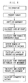
- Fig. 5 is a flow chart showing specific operation of one embodiment of the present invention.
- Fig. 6 shows an example of display of eye movement of a healthy person when target is moved from B to E.
- Fig. 7 shows an example of display of healthy person's eye movement when the target is moved from C to D.
- Fig. 8 shows an example of display of eye movement of a patient in a moderate stage of Alzheimer's disease, age 52, when the target is moved from B to E.
- Fig. 9 shows an example of display of the eye movement of a patient in a moderate stage of Alzheimer's disease, age 52, when the target is moved from C to D.
- Fig. 10 shows an example of display of the eye movement of a patient in a moderate stage of Alzheimer's disease, age 66, when the target is moved from B to E.
- Fig. 11 shows an example of display of the eye movement of a patient in a moderate stage of Alzheimer's disease, age 66, when the target is moved from C to D.
- Fig. 12 shows an example of parameters of the eye movement.
- Fig. 13 shows an example of measurement of asymmetry of left and right saccades of a patient suffering from Alzheimer's disease.
- Fig. 14 shows latency of vergence eye movement measured.
- Fig. 15 shows time constant of the vergence eye movement.
- Fig. 16 shows amplitude of change in convergence angle.
- Fig. 17 shows number of saccades.
- Fig. 18 is a block diagram showing another embodiment of the present invention.
- Fig. 19 shows a specific example of the head movement detecting portion shown in Fig. 18.
- Fig. 20 is an illustration of the head coordinate system.
- Fig. 21 is a flow chart showing operation of said another embodiment of the present invention.
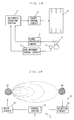
- Fig. 1 is a schematic block diagram of one embodiment of the present invention.
- an eye movement detecting portion 2 detects eye movement of a subject, and the output of detection is applied to a signal processing circuit 5 to be processed and applied to an arithmetic operation portion 1.
- a personal computer or a work station is used as the arithmetic operation portion 1.
- a target control circuit 3 lights targets on a plate for calibration 4 in accordance with an instruction from the arithmetic operation portion 1.
- three light emitting diodes A, B and C are provided distant from the subject and three light emitting diodes D, E and F are provided near the subject, on the plate 4.
- the targer is not limited to the diodes, and any means which can be recognized by the subject may be used.
- the light emitting diodes are lit in the order of A ⁇ F, B ⁇ E and C ⁇ D, for example, and the eye movement of the subject at that time is detected by the eye movement detecting portion.
- Fig. 2 shows a specific example of the eye movement detecting portion shown in Fig. 1
- Fig. 3 shows the operation of the eye movement detecting portion.
- the eye movement detecting portion 2 is attached to goggles, and the subject wears the goggles.
- the eye movement detecting portion 2 utilizes limbus reflection method and provided with detecting portions 21 and 22 for detecting movement of left and right eyes.
- the detecting portions 21 and 22 each include a light emitting diode 24 provided centered with respect to the eye ball 23 and photodiodes 25 and 26 provided on both sides of the diode 24.
- a light emitting diode radiating infrared rays having relatively wide directivity of about ⁇ 21° is used as the light emitting diode 24, while ones having acute directivity of about ⁇ 10° are used as the photodiodes 25 and 26.
- the light beam emitted from the light emitting diode 24 to the eye ball 23 is reflected from the iris of the eye 28 and from the white of the eye 27 with different reflectivity, and the difference in reflectivity is amplified by an operational amplifier 29. If the difference is calculated, a horizontal output (left and right) is obtained as shown in Fig. 3(b), and if the sum is calculated by an operation amplifier 30, a vertical (up and down) output is obtained as shown in Fig. 3(c).
- the eye movement detecting portion 2 may utilize a contact lens (the search coil method) or a TV camera (the cornea reflection method), other than aforementioned limbus reflection method.
- Fig. 4 shows lighting sequence of the light emitting diodes on the board for calculation
- Fig. 5 is a flow chart showing specific operation of one embodiment of the present invention.
- Figs. 1 to 5 A specific operation of one embodiment of the present invention will be described with reference to Figs. 1 to 5.
- the subject wears the goggles provided with the eye movement detecting portion 2 shown in Fig. 2 on his head.
- a head-chin rest or a bite board is used.
- the calibration is effected. This is because that detection output of the eye movement detecting portion differs subject by subject. Details of the calibration is disclosed in Medical and Biological Engineering and Computing July, 1990. More specifically, in place of the board for calibration 4, a calibration board provided with a plurality of light emitting diodes arranged in the periphery is prepared. The light emitting diodes are lit successively, the level of detection output from the eye movement detecting portion 2 at that time is determined, and the level is adjusted such that a prescribed output is obtained from a signal processing circuit 5.
- the arithmetic operation portion 1 gives an instruction to the target control circuit 3 to light light emitting diodes of the board 4, and thus presents a target.
- the presentation of the target is carried out such that a light emitting diode A arranged at a distant and a light emitting diode F arranged close to the subject are lit alternately.
- there are three combinations of close and distant targets that is, the diodes A and F, B and E, and C and D as shown in Fig. 4.
- the number and the combination of the targets may be increased or decreased. Further, when the target is lit, an alarm sound may be given so as to attract attention of the subject.
- eye movement of the subject when the gaze is shifted in the depth direction is measured, and the result of measurement is stored in a memory device (hard disc, floppy disc or the like) included in the arithmetic operation portion 1.
- the measured eye movement is analyzed by the arithmetic operation portion 1.
- Figs. 6 to 17 shows example of measurement in accordance with one embodiment of the present invention.
- Fig. 6 is an example of display of eye movement of a healthy person when the target is changed from B to E
- Fig. 7 shows an example of display of the healthy person's eye movement when the target is changed to C to D.
- the reference character a represents horizontal eye movement of the left eye
- b represents horizontal eye movement of the right eye
- c represents a change in convergence angle
- d represents vertical eye movement of the right eye
- e represents vertical eye movement of the left eye.
- the left and right eyes move in opposite directions, vergence eye movement which is a relatively slow movement is generated, the gazing is shifted from the distant point to the close point, and the convergence angle c is increased.
- the targets are arranged in asymmetry in left and right directions. Therefore, at first, very rapid eye movement called saccade is generated in asymmetry, then vergence movement, which is relatively slow eye movement occurs, increasing the angle of convergence.
- Fig. 8 shows an example of display of the eye movement of a patient in a moderate stage of Alzheimer's disease, age 52, when the target is moved from B to E.
- Fig. 9 shows an example of display of a patient in a moderate stage of Alzheimer's disease when the target is moved from C to D.
- the result of measurement of the patient suffering from Alzheimer's disease is considerably different from that of a healthy person.
- asymmetrical eye movement between left and right targets B an E is required, asymmetrical saccade which is rapid eye movement frequently occurs, and slow vergence eye movement is not so frequently observed.
- the monotonous change as in a healthy person is not recognized and the amplitude thereof is small.
- asymmetrical saccade is generated at the initial stage of reaction, and then slow vergence eye movement occurs thereafter.
- the angle c once decreases because of the asymmetrical saccade at first, and then vergence eye movement occurs as to compensate for the decrease.
- the convergence angle c decreases once and the original angle is simply resumed.
- Fig. 10 shows an example of display of the eye movement of a patient in a moderate stage of Alzheimer's disease, age 66, when the target is moved from B to E.
- Fig. 11 is an example of display of the eye movement of the patient in a moderate stage of Alzheimer's disease when the target is moved from C to D.
- the reaction of this patient is little different from that of the patient of Alzheimer's disease discussed with reference to Figs. 8 and 9.
- saccade is not frequently observed in the initial stage of reaction but saccade is observed when vergence eye movement, which is the slow eye movement is generated. Start of the vergence eye movement is delayed very much as compared with the example of a healthy person shown in Figs. 6 and 7.
- the change in the convergence angle is not monotonous but instable. Even in the target arrangement which is asymmetrical shown in Fig. 11, asymmetrical saccade is observed in the initial stage of reaction. However, though the condition is to move the eye from the distant point to the close point, the convergence angle reduces at first and after a considerable delay, a slow vergence eye movement occurs. As for the velocity of vergence eye movement, it is slower as compared with a healthy person discussed with reference to Figs. 6 and 7.
- asymmetrical saccade in the initial stage of reaction when symmetrical eye movement is required may be regarded as particular characteristics of the eye movement of a patient suffering from Alzheimer's disease.
- the arithmetic operation portion 1 calculates the time change of the convergence angle, detects the number of occurrence of saccade, calculates latency of the vergence eye movement, calculates time constant of the vergence eye movement, calculates amplitude of the vergence eye movement, and calculates asymmetry of saccade, on the basis of the output from the eye movement detecting portion 2, in accordance with the manner shown in Fig. 5.
- Fig. 12 shows an example of parameters of the eye movement.
- the number N of occurrence of saccade is obtained by calculating the number of saccade in a predetermined time period after lighting of the target.
- the method of detecting saccade it can be easily detected by counting portion (denoted by #) where the eye moves rapidly from the graph of the eye movement shown in Fig. 12, by determining such portions with reference to the velocity of eye movement and so on.
- the latency L of vergence eye movement means the time from lighting of target to the start of the movement of eye.
- the convergence angle (the value of the angle in the direction of the left eye minus the value of the angle in the direction of the right eye) is calculated, and latency is obtained by subtracting the time of lighting the target from the time at which this value changes exceeding a certain threshold value (for example, about 0.5°).
- a certain threshold value for example, about 0.5°
- the change of the convergence angle may be calculated to find the time at which the eye movement starts on the basis of the calculated change of the convergence angle.
- the change of the convergence angle is calculated and the amplitude when the change in the angle is not observed is measured.
- the change of the convergence angle is not monotonous in case of patients suffering from Alzheimer's disease, and therefore maximum value of amplitude may be used.
- the monotony of the change of the convergence angle the time change of the convergence angle may be directly observed or velocity component or acceleration component may be calculated and whether such component changes frequently or not may determined.
- Fig. 13 shows an example of measurement of asymmetry in left and right saccade of a patient suffering from Alzheimer's disease.
- Asym (AL - AR)/(AL + AR)
- Asym (AL - AR)/(AL + AR)
- saccade in eye movement on a line in front of one's face is symmetrical in left and right directions and therefore Asym ⁇ 0.
- the value of Asym is not 0, as shown in Fig. 13.
- a higher order lag system may be defined as a mechanism for controlling eye movement, parameters may be fitted approximately on a curve on the basis of the measured waveform, and latency of vergence eye movement, constant and amplitude may be calculated on the basis of the values of the parameters.
- Figs. 14 to 17 show examples of actually measured parameters in which Fig. 14 shows latency in vergence eye movement, Fig. 15 shows time constant, Fig. 16 shows amplitude and Fig. 17 shows the number of occurrence of saccade.
- "Alz mild” represents a patient in a mild stage of Alzheimer's disease
- "Alz moderate” represents a patient in a moderate stage of Alzheimer's disease
- "MID” represents a patient suffering from multi-infarct dementia
- OPCA denotes a patient suffering from olivopontocerebellar atrophy, and the remaining are healthy persons.
- Fig. 14 shows latency in vergence eye movement
- Fig. 15 shows time constant
- Fig. 16 shows amplitude
- Fig. 17 shows the number of occurrence of saccade.
- "Alz mild” represents a patient in a mild stage of Alzheimer's disease
- "Alz moderate” represents a patient in a moderate stage of Alzheimer's disease
- MID represents
- the latency of vergence eye movement of a patient suffering from Alzheimer's disease is long, and time constant is also long when the disease is advanced to a moderate stage.
- the amplitude of the change of the convergence angle of the patient suffering from Alzheimer's disease is smaller as shown in Fig. 16, and the number of occurrence of saccade tends to be increased as shown in Fig. 17. Since there are exceptions in each parameter, it may be difficult to discriminate Alzheimer's disease from other disease (MID ⁇ OPCA) or from the healthy person perfectly when only one parameter is used. However, discrimination of Alzheimer's disease can be done easily when all these parameters (latency, time constant, amplitude, number of saccades and asymmetry of the left and right eyes) are used for determination. More accurate discrimination can be realized if conventional Hachinski's ischemic score, computer tomography (CT) of the brain and so on are used in addition to the above described results of measurement.
- CT computer tomography
- Fig. 18 is a block diagram showing another embodiment of the present invention and Fig. 19 shows a specific example of the head movement detecting portion shown in Fig. 18.
- a head movement detecting portion 6 and a head movement control circuit 7 are provided. Except this point, the structure is the same as that shown in Fig. 1.
- the head movement detecting portion 6 includes an orthogonal coil serving as a source 61 and an orthogonal coil serving as a sensor 62 as shown in Fig. 19.
- the head movement control circuit 7 includes a control portion 71, a drive circuit 72 and a detecting circuit 73.
- the drive circuit 72 drives the orthogonal coil of the source 61 to generate a magnetic field in response to an instruction from the control portion 71.
- the head movement detecting portion 6 When the subject wearing the head movement detecting portion 6 moves, a voltage is induced in the sensor 62, the voltage is detected by the detecting circuit 73 and the detected output is calculated by the control portion 71, so that data corresponding to the movement of the head is output.
- the head movement detecting portion 6 is attached to the goggles shown in Fig. 2.
- Fig. 20 is an illustration showing the principle of the head coordinate system with the subject being the center.
- the head coordinate system detected by the head movement detecting portion 6 will be described.
- the head coordinate system includes two systems, that is, XY coordinate system realized by the translational movement of the subject with respect to the object of monitoring such as shown in Fig. 20(a), and a polar coordinate system based on the rotation movement of the head such as shown in Fig. 20(b).
- the amount of head movement in respective coordinate systems are defined as (Hx, Hy, Hz), (H ⁇ , H ⁇ , H ⁇ ).
- the direction toward the object of monitoring is represented by the Y axis
- the horizontal movement is represented by the X axis
- the vertical movement is represented by the Z axis, as an example.
- H ⁇ represents the rotation of the X axis, that is, the movement of one's neck upward or downward.
- H ⁇ represents the rotation of the Y axis, that is, the movement of inclining ones neck once from the left shoulder to the right shoulder.
- H ⁇ represents rotation in the Z axis, that is, rotation of one's neck in the left or right direction.
- Fig. 21 is a flow chart showing the operation of another embodiment of the present invention.
- target in the depth direction are presented by the board 4 for calibration in the same manner as discussed above with reference to Fig. 1, the eye movement of the subject at that time is detected by the eye movement detecting portion 2, and the head movement of the subject is detected by the head movement detecting portion 6.
- the arithmetic operation portion 1 carries out the operations in accordance with the equations (1) to (8) on the basis of the detected head movement data and the eye movement data, and calculates parameters in the same manner as in the embodiment shown in Fig. 1. More specifically, in place of Xeye and Yeye in the embodiment shown in Fig.
- the number of occurrence of saccade when the gaze is shifted in the depth direction, latency of the vergence eye movement, time constant of the vergence eye movement, amplitude of change of the convergence angle, monotony of change, asymmetry of saccade when symmetrical eye movement is required are calculated by using the gaze shift Vx and Vy calculated in accordance with the equations (7) and (8).
- the method of calculating these parameters are the same as those described with reference to Fig. 1, and diagnosis of Alzheimer's disease is done utilizing the measured values of these parameters generally.
- a target for depth perception is presented to a subject, movement of left and right eyes of the subject is detected and disorder in gaze shift in the depth direction of the subject is determined based on the detected output. Therefore, disorder in mechanism for controlling eye movement, depth perception, position in the brain of the subject can be easily detected, and accordingly, Alzheimer's disease can be discriminated from cerebrovascular disease.
Applications Claiming Priority (2)
| Application Number | Priority Date | Filing Date | Title |
|---|---|---|---|
| JP4247780A JPH08104B2 (ja) | 1992-09-17 | 1992-09-17 | 奥行き視線移動検査装置 |
| JP247780/92 | 1992-09-17 |
Publications (3)
| Publication Number | Publication Date |
|---|---|
| EP0587976A2 true EP0587976A2 (de) | 1994-03-23 |
| EP0587976A3 EP0587976A3 (de) | 1995-04-05 |
| EP0587976B1 EP0587976B1 (de) | 1997-09-24 |
Family
ID=17168544
Family Applications (1)
| Application Number | Title | Priority Date | Filing Date |
|---|---|---|---|
| EP93103154A Expired - Lifetime EP0587976B1 (de) | 1992-09-17 | 1993-02-26 | Gerät zur Untersuchung des Blickwechsels in Tiefenrichtung |
Country Status (6)
| Country | Link |
|---|---|
| US (1) | US5382989A (de) |
| EP (1) | EP0587976B1 (de) |
| JP (1) | JPH08104B2 (de) |
| KR (1) | KR960006648B1 (de) |
| CA (1) | CA2090358C (de) |
| DE (1) | DE69314126T2 (de) |
Families Citing this family (30)
| Publication number | Priority date | Publication date | Assignee | Title |
|---|---|---|---|---|
| JP3396062B2 (ja) * | 1993-08-26 | 2003-04-14 | オリンパス光学工業株式会社 | 画像表示装置 |
| JPH07128579A (ja) * | 1993-10-29 | 1995-05-19 | Canon Inc | 視線検知方法、視線検知手段及び該視線検知手段を有する映像機器 |
| JPH0830380A (ja) * | 1994-05-10 | 1996-02-02 | Minolta Co Ltd | 表示装置 |
| AU4197496A (en) * | 1994-10-28 | 1996-05-23 | Eyesys Technologies, Inc. | Multi-camera corneal analysis system |
| US6373961B1 (en) | 1996-03-26 | 2002-04-16 | Eye Control Technologies, Inc. | Eye controllable screen pointer |
| US5861936A (en) * | 1996-07-26 | 1999-01-19 | Gillan Holdings Limited | Regulating focus in accordance with relationship of features of a person's eyes |
| US6027216A (en) * | 1997-10-21 | 2000-02-22 | The Johns University School Of Medicine | Eye fixation monitor and tracker |
| US6433760B1 (en) | 1999-01-14 | 2002-08-13 | University Of Central Florida | Head mounted display with eyetracking capability |
| AUPQ748800A0 (en) * | 2000-05-12 | 2000-06-08 | Commonwealth Scientific And Industrial Research Organisation | Computer diagnosis and screening of mood disorders |
| JP2002017677A (ja) * | 2000-07-07 | 2002-01-22 | Hamamatsu Photonics Kk | 輻輳角測定装置 |
| US6965226B2 (en) * | 2000-09-05 | 2005-11-15 | Cascade Microtech, Inc. | Chuck for holding a device under test |
| KR20030087101A (ko) * | 2002-05-06 | 2003-11-13 | 고종선 | 안구운동 분석을 위한 새로운 저속도 측정 방법 |
| US20050110950A1 (en) * | 2003-03-13 | 2005-05-26 | Thorpe William P. | Saccadic motion sensing |
| US7872635B2 (en) * | 2003-05-15 | 2011-01-18 | Optimetrics, Inc. | Foveated display eye-tracking system and method |
| JP2006136450A (ja) * | 2004-11-11 | 2006-06-01 | Matsushita Electric Ind Co Ltd | 虹彩認証装置 |
| US9301679B2 (en) | 2007-11-01 | 2016-04-05 | Dignity Health | Method of detecting neurological disease |
| JP5593039B2 (ja) * | 2009-05-29 | 2014-09-17 | 進 新谷 | 認知能力検査システム |
| KR101046677B1 (ko) * | 2011-03-15 | 2011-07-06 | 동국대학교 산학협력단 | 눈 위치 추적방법 및 이를 이용한 의료용 헤드램프 |
| CA2855968C (en) | 2011-11-22 | 2018-06-19 | Dignity Health | System and method for using microsaccade peak velocity as a measure of mental workload and fatigue |
| CA2912426C (en) | 2013-05-31 | 2023-09-26 | Dignity Health | System and method for detecting neurological disease |
| US10206568B2 (en) * | 2014-05-23 | 2019-02-19 | Natus Medical Incorporated | Head mountable device for measuring eye movement |
| AU2015274601B2 (en) | 2014-06-11 | 2020-02-27 | Arizona Board Of Regents On Behalf Of Arizona State University | Systems and methods for non-intrusive deception detection |
| AU2015305371B2 (en) | 2014-08-21 | 2019-11-21 | Dignity Health | Systems and methods for using eye movements to determine traumatic brain injury |
| WO2016133588A1 (en) * | 2015-02-20 | 2016-08-25 | REBIScan, Inc. | Method and apparatus for fixation measurement and refraction error measurement using wave-front error |
| CN105496347B (zh) * | 2016-01-12 | 2017-06-06 | 哈尔滨学院 | 视深度电子测量装置 |
| US20170354326A1 (en) * | 2016-06-10 | 2017-12-14 | Johnson & Johnson Vision Care, Inc. | Electronic ophthalmic lens with medical monitoring |
| CN109276228B (zh) * | 2017-07-21 | 2020-12-25 | 成都集思鸣智科技有限公司 | 一种检测大脑功能的系统及其装置 |
| CN112220448B (zh) * | 2020-10-14 | 2022-04-22 | 北京鹰瞳科技发展股份有限公司 | 眼底相机及眼底图像合成方法 |
| WO2023281621A1 (ja) * | 2021-07-06 | 2023-01-12 | 日本電気株式会社 | 回復度推定装置、回復度推定方法、及び、記録媒体 |
| WO2023281622A1 (ja) * | 2021-07-06 | 2023-01-12 | 日本電気株式会社 | 回復度推定装置、回復度推定方法、及び、記録媒体 |
Citations (4)
| Publication number | Priority date | Publication date | Assignee | Title |
|---|---|---|---|---|
| FR2593381A1 (fr) * | 1986-01-28 | 1987-07-31 | Pavlidis George | Procede et moyens de detection de la dyslexie |
| EP0487855A1 (de) * | 1990-11-27 | 1992-06-03 | Atr Auditory And Visual Perception Research Laboratories | Verfahren zur Untersuchung des Bewegungssystems des Auges |
| EP0578907A2 (de) * | 1992-07-09 | 1994-01-19 | Atr Auditory And Visual Perception Research Laboratories | Medizinisches Diagnostikgerät mit Feststellung der Blickrichtung |
| EP0582772A1 (de) * | 1992-08-12 | 1994-02-16 | Atr Auditory And Visual Perception Research Laboratories | Medizinisches Diagnosegerät zur Erkennung von Erkrankungen des Gehirns |
Family Cites Families (10)
| Publication number | Priority date | Publication date | Assignee | Title |
|---|---|---|---|---|
| US2168308A (en) * | 1939-08-08 | Testing perception of space | ||
| DE250657C (de) * | 1900-01-01 | |||
| US3609016A (en) * | 1969-12-30 | 1971-09-28 | Optical Sciences Group Inc | Vision-testing device for visually displaying a calibrated signal to the eye and recording the responsive movement thereto |
| SU625687A1 (ru) * | 1977-01-05 | 1978-09-30 | Казанский Ордена Трудового Красного Знамени Государственный Университет Имени В.И.Ульянова-Ленина | Устройство дл регистрации и перемещени взора |
| GB2103045A (en) * | 1981-07-31 | 1983-02-09 | Omer Mohamed Abdel Gadir | Microprocessor-based eye motion analysis system |
| US4528989A (en) * | 1982-10-29 | 1985-07-16 | Weinblatt Lee S | Screening method for monitoring physiological variables |
| US4838681A (en) * | 1986-01-28 | 1989-06-13 | George Pavlidis | Method and means for detecting dyslexia |
| SE8703639D0 (sv) * | 1987-09-21 | 1987-09-21 | Udden | Eye movement measurement device with multiple light emitting and detecting elements |
| US5260734A (en) * | 1989-11-30 | 1993-11-09 | Asahi Kogaku Kogyo Kabushiki Kaisha | Determining a direction in which an eye gazes |
| JPH0749036B2 (ja) * | 1991-02-28 | 1995-05-31 | 株式会社エイ・ティ・アール視聴覚機構研究所 | 両眼眼球運動測定装置 |
-
1992
- 1992-09-17 JP JP4247780A patent/JPH08104B2/ja not_active Expired - Fee Related
-
1993
- 1993-02-25 CA CA002090358A patent/CA2090358C/en not_active Expired - Fee Related
- 1993-02-26 EP EP93103154A patent/EP0587976B1/de not_active Expired - Lifetime
- 1993-02-26 DE DE69314126T patent/DE69314126T2/de not_active Expired - Fee Related
- 1993-03-05 KR KR1019930003262A patent/KR960006648B1/ko not_active IP Right Cessation
- 1993-03-16 US US08/031,973 patent/US5382989A/en not_active Expired - Fee Related
Patent Citations (4)
| Publication number | Priority date | Publication date | Assignee | Title |
|---|---|---|---|---|
| FR2593381A1 (fr) * | 1986-01-28 | 1987-07-31 | Pavlidis George | Procede et moyens de detection de la dyslexie |
| EP0487855A1 (de) * | 1990-11-27 | 1992-06-03 | Atr Auditory And Visual Perception Research Laboratories | Verfahren zur Untersuchung des Bewegungssystems des Auges |
| EP0578907A2 (de) * | 1992-07-09 | 1994-01-19 | Atr Auditory And Visual Perception Research Laboratories | Medizinisches Diagnostikgerät mit Feststellung der Blickrichtung |
| EP0582772A1 (de) * | 1992-08-12 | 1994-02-16 | Atr Auditory And Visual Perception Research Laboratories | Medizinisches Diagnosegerät zur Erkennung von Erkrankungen des Gehirns |
Non-Patent Citations (1)
| Title |
|---|
| YOSHINOBU EBISAWA ET AL: 'relation between attention and characteristics of saccade during tracking eye movement' SYSTEMS & COMPUTERS IN JAPAN vol. 19, no. 10, October 1988, SILVER SPRING, US, pages 70 - 78, XP000050107 * |
Also Published As
| Publication number | Publication date |
|---|---|
| EP0587976A3 (de) | 1995-04-05 |
| DE69314126D1 (de) | 1997-10-30 |
| KR960006648B1 (ko) | 1996-05-22 |
| JPH0690903A (ja) | 1994-04-05 |
| CA2090358A1 (en) | 1994-03-18 |
| DE69314126T2 (de) | 1998-03-05 |
| CA2090358C (en) | 1997-04-15 |
| EP0587976B1 (de) | 1997-09-24 |
| KR940006545A (ko) | 1994-04-25 |
| US5382989A (en) | 1995-01-17 |
| JPH08104B2 (ja) | 1996-01-10 |
Similar Documents
| Publication | Publication Date | Title |
|---|---|---|
| EP0587976B1 (de) | Gerät zur Untersuchung des Blickwechsels in Tiefenrichtung | |
| US5365941A (en) | Apparatus for detecting small involuntary movement | |
| US5311879A (en) | Medical diagnostic apparatus utilizing line-of-sight detection | |
| US6669651B1 (en) | Non-invasive brain function examination | |
| CN104159497B (zh) | 用于评估视觉系统的功能的方法及其装置 | |
| EP3079560B1 (de) | Verfahren zum betrieb einer augenverfolgungsvorrichtung und augenverfolgungsvorrichtung zur bereitstellung einer aktiven beleuchtungssteuerung für verbesserte augenverfolgungsrobustheit | |
| EP0590231B1 (de) | Analysengerät der Tiefenwahrnehmung | |
| CA2090359C (en) | Apparatus for medical diagnosis utilizing masking of fixation point | |
| US5604818A (en) | Apparatus for measuring sighting direction | |
| US5305764A (en) | Medical diagnostic apparatus utilizing line-of-sight detection | |
| JP2012530573A (ja) | 凝視制御装置および眼球の凝視を制御するための方法 | |
| JP6957048B2 (ja) | 眼部画像処理装置 | |
| Ramaioli et al. | Vestibulo-ocular responses and dynamic visual acuity during horizontal rotation and translation | |
| Priot et al. | Partitioning the components of visuomotor adaptation to prism-altered distance | |
| Vishwanath et al. | Saccadic localization of occluded targets | |
| Hoshino et al. | A compact wearable eye movement measurement system for support of safe driving | |
| JP2615807B2 (ja) | 視覚情報分析装置 | |
| US11653831B2 (en) | Visual performance examination device, visual performance examination method, and computer program | |
| El Moucary et al. | Commodious Control Apparatus for Impaired People | |
| Lutwak et al. | User Self-Motion Modulates the Perceptibility of Jitter for World-locked Objects in Augmented Reality | |
| JP2023032223A (ja) | 生体情報解析装置 | |
| Mühlberger et al. | An unobtrusive measurement method of the horizontal gaze angle | |
| MUHLBERGER et al. | of the horizontal gaze angle |
Legal Events
| Date | Code | Title | Description |
|---|---|---|---|
| PUAI | Public reference made under article 153(3) epc to a published international application that has entered the european phase |
Free format text: ORIGINAL CODE: 0009012 |
|
| AK | Designated contracting states |
Kind code of ref document: A2 Designated state(s): DE FR GB NL SE |
|
| PUAL | Search report despatched |
Free format text: ORIGINAL CODE: 0009013 |
|
| AK | Designated contracting states |
Kind code of ref document: A3 Designated state(s): DE FR GB NL SE |
|
| 17P | Request for examination filed |
Effective date: 19950921 |
|
| GRAG | Despatch of communication of intention to grant |
Free format text: ORIGINAL CODE: EPIDOS AGRA |
|
| RTI1 | Title (correction) | ||
| 17Q | First examination report despatched |
Effective date: 19970204 |
|
| RTI1 | Title (correction) | ||
| GRAH | Despatch of communication of intention to grant a patent |
Free format text: ORIGINAL CODE: EPIDOS IGRA |
|
| GRAH | Despatch of communication of intention to grant a patent |
Free format text: ORIGINAL CODE: EPIDOS IGRA |
|
| GRAA | (expected) grant |
Free format text: ORIGINAL CODE: 0009210 |
|
| AK | Designated contracting states |
Kind code of ref document: B1 Designated state(s): DE FR GB NL SE |
|
| REF | Corresponds to: |
Ref document number: 69314126 Country of ref document: DE Date of ref document: 19971030 |
|
| ET | Fr: translation filed | ||
| PLBE | No opposition filed within time limit |
Free format text: ORIGINAL CODE: 0009261 |
|
| STAA | Information on the status of an ep patent application or granted ep patent |
Free format text: STATUS: NO OPPOSITION FILED WITHIN TIME LIMIT |
|
| 26N | No opposition filed | ||
| REG | Reference to a national code |
Ref country code: GB Ref legal event code: IF02 |
|
| PGFP | Annual fee paid to national office [announced via postgrant information from national office to epo] |
Ref country code: GB Payment date: 20020204 Year of fee payment: 10 |
|
| PGFP | Annual fee paid to national office [announced via postgrant information from national office to epo] |
Ref country code: NL Payment date: 20020214 Year of fee payment: 10 |
|
| PGFP | Annual fee paid to national office [announced via postgrant information from national office to epo] |
Ref country code: FR Payment date: 20020221 Year of fee payment: 10 Ref country code: SE Payment date: 20020221 Year of fee payment: 10 |
|
| PGFP | Annual fee paid to national office [announced via postgrant information from national office to epo] |
Ref country code: DE Payment date: 20020304 Year of fee payment: 10 |
|
| PG25 | Lapsed in a contracting state [announced via postgrant information from national office to epo] |
Ref country code: GB Free format text: LAPSE BECAUSE OF NON-PAYMENT OF DUE FEES Effective date: 20030226 |
|
| PG25 | Lapsed in a contracting state [announced via postgrant information from national office to epo] |
Ref country code: SE Free format text: LAPSE BECAUSE OF NON-PAYMENT OF DUE FEES Effective date: 20030227 |
|
| PG25 | Lapsed in a contracting state [announced via postgrant information from national office to epo] |
Ref country code: NL Free format text: LAPSE BECAUSE OF NON-PAYMENT OF DUE FEES Effective date: 20030901 |
|
| PG25 | Lapsed in a contracting state [announced via postgrant information from national office to epo] |
Ref country code: DE Free format text: LAPSE BECAUSE OF NON-PAYMENT OF DUE FEES Effective date: 20030902 |
|
| EUG | Se: european patent has lapsed | ||
| GBPC | Gb: european patent ceased through non-payment of renewal fee | ||
| PG25 | Lapsed in a contracting state [announced via postgrant information from national office to epo] |
Ref country code: FR Free format text: LAPSE BECAUSE OF NON-PAYMENT OF DUE FEES Effective date: 20031031 |
|
| NLV4 | Nl: lapsed or anulled due to non-payment of the annual fee |
Effective date: 20030901 |
|
| REG | Reference to a national code |
Ref country code: FR Ref legal event code: ST |