EP0587964A1 - Instrument for centering corrective lenses - Google Patents
Instrument for centering corrective lenses Download PDFInfo
- Publication number
- EP0587964A1 EP0587964A1 EP92830490A EP92830490A EP0587964A1 EP 0587964 A1 EP0587964 A1 EP 0587964A1 EP 92830490 A EP92830490 A EP 92830490A EP 92830490 A EP92830490 A EP 92830490A EP 0587964 A1 EP0587964 A1 EP 0587964A1
- Authority
- EP
- European Patent Office
- Prior art keywords
- rod
- instrument
- frame
- corrective lenses
- bearing
- Prior art date
- Legal status (The legal status is an assumption and is not a legal conclusion. Google has not performed a legal analysis and makes no representation as to the accuracy of the status listed.)
- Granted
Links
- 230000000007 visual effect Effects 0.000 claims description 15
- 230000000694 effects Effects 0.000 claims description 7
- 239000011521 glass Substances 0.000 claims description 4
- 210000001508 eye Anatomy 0.000 description 4
- 230000003287 optical effect Effects 0.000 description 4
- 210000000873 fovea centralis Anatomy 0.000 description 2
- 210000001525 retina Anatomy 0.000 description 2
- 208000019749 Eye movement disease Diseases 0.000 description 1
- 208000029091 Refraction disease Diseases 0.000 description 1
- 230000004075 alteration Effects 0.000 description 1
- 230000004430 ametropia Effects 0.000 description 1
- 208000003464 asthenopia Diseases 0.000 description 1
- 210000005252 bulbus oculi Anatomy 0.000 description 1
- 230000004927 fusion Effects 0.000 description 1
- 210000002189 macula lutea Anatomy 0.000 description 1
- 238000011084 recovery Methods 0.000 description 1
- 230000011514 reflex Effects 0.000 description 1
- 208000014733 refractive error Diseases 0.000 description 1
Images

Classifications
-
- G—PHYSICS
- G02—OPTICS
- G02C—SPECTACLES; SUNGLASSES OR GOGGLES INSOFAR AS THEY HAVE THE SAME FEATURES AS SPECTACLES; CONTACT LENSES
- G02C13/00—Assembling; Repairing; Cleaning
- G02C13/003—Measuring during assembly or fitting of spectacles
- G02C13/005—Measuring geometric parameters required to locate ophtalmic lenses in spectacles frames
-
- A—HUMAN NECESSITIES
- A61—MEDICAL OR VETERINARY SCIENCE; HYGIENE
- A61B—DIAGNOSIS; SURGERY; IDENTIFICATION
- A61B3/00—Apparatus for testing the eyes; Instruments for examining the eyes
- A61B3/10—Objective types, i.e. instruments for examining the eyes independent of the patients' perceptions or reactions
- A61B3/11—Objective types, i.e. instruments for examining the eyes independent of the patients' perceptions or reactions for measuring interpupillary distance or diameter of pupils
- A61B3/111—Objective types, i.e. instruments for examining the eyes independent of the patients' perceptions or reactions for measuring interpupillary distance or diameter of pupils for measuring interpupillary distance
Definitions
- the invention refers to an optical instrument to measure the distance between the person visual axes for the centering of the corrective lenses.
- Said lenses to correct the ametropia are prescribed to the patient by prescription of the oculist and are predisposed by the optician who must then apply the same on the frame.
- the optician using a binocular unit: the interpupillometer, as a first step measures the interpupillary distance of the person and on the base of this he operates on the glass frame.
- the invented instrument basing on the fact that to do not make oneself suffer ocular deviations for the correct fusion recovery of the image acquisition is necessary that the optical centres of the lenses were placed where come to pass the visual axes, foresees an instrument with two opposite mirrors to operate a total image reflection which permits to determine the distance between said visual axes of the examined person acting by two consecutive monocular bearings.
- the distance is computed by difference of the millimetric measures read in said bearings onto the reflex image on the mirror, foreseen on the bottom of the instrument chamber, of a graduated scale bringing in each of the bearings a measure indicator in total reflexion position by a micrometric translation regulator with manual or electronic drive.
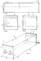
- the invented instrument foresees a closed frame to form an inside parallelepiped reflexion chamber including on its front and back walls a system of two mirrors with opposite parallel disposition: a mirror 1, working with couple of circular plate areas 2 with semireflecting effect to permit the bearings and with applied on the upper part a millimetric scale 3, and other mirror 4 on which presses a mobile frame 5 supporting a bearing reference with mark rod 6 manually transfer by a micrometric regulator with knob 7.
- the instrument fore sees, in correspondence with the circular plate areas 2 of the mirror 1 working with semireflecting effect, observation holes 9 and 10 on which are set out the test corrective lenses by parabolic guides 11.
- the reflexion chamber is illuminated by couple of bright diffuser 12 disposed in the middle on the lateral walls of the frame.
- the optician applys, as prescribed by the oculist, the test corrective lenses 13 and 14 on the parabolic guides 11 and he switch on the light into the reflexion chamber by switch 15.
- the person with an eye closed effects with the open eye the first monocular bearing through the correspondence observation hole 9 or 10.
- the person Owing to the system of total reflexion mirrors the person will see on the bottom mirror 4, in specular position to that of real disposition, the reflected images 16 of the millimetric scale 3 on which come to press the bearing mark rod 6 and, in the case of said rod does not come to be on the visual axis of the eye under observation, he sees a set of images: that of the real rod 6 and that reflected 17. To bring the rod 6 on the visual axis the person will move the knob 7 of the micrometric regulator for translation of the frame 5 which bears the rod untill two said images come to lie over and will be seen only the real image 6. The person reads then the measure on the reflected image.
- FIG. 1 is longitudinal section view of the instrument to show the operative system foreseen into the reflection chamber.
- Fig. 2 is view on the bottom mirror 4 of the bearing mark with the rod 6 not in position on the visual axis of the person looking while fig. 3 is view as in previous figure but with the rod bringing in position by knob 7.
- Fig. 4 is perspective view of the instrument closed frame with walls against the light to show the details into the reflexion chamber.
- fig. 5 is schematic view of the scientific principle to which the invented instrument is conformed.
- the retina 18 of the eyeball with point F to indicate 1a fovea centralis, where the sight is more sharp, and point N to indicate the intersection between the visual axis 19 and the optic axis 20.
- point N to indicate the intersection between the visual axis 19 and the optic axis 20.
- the pupillar axis 21 is indicated the look axis 22 and the fixing axis 23 intersects the optic axis in point C.
- Fig. 6 is frontal view of the instrument with test corrective lenses 13 and 14 in position on the parabolic guides 11.
- Fig. 7 is perspective view of the instrument closed frame with walls against the light seen in opposite disposition to that showing in fig. 4.
- FIG. 8 is view with person profile during a monocular observation using an instrument with parallelepiped frame placed in elevation on support plane.
- Fig. 9 is view with person profile during a monocular observation using an instrument with parallelepiped frame horizontally leant on plane.
- the translation movement of frame 5 to move the rod 6 in position on the bearing mark is realized in electronic way.
- the frame shape, the bearing and read means, the drive and translation means could be foreseen in different way on the base of the use necessities.
Landscapes
- Health & Medical Sciences (AREA)
- Physics & Mathematics (AREA)
- Life Sciences & Earth Sciences (AREA)
- Ophthalmology & Optometry (AREA)
- Surgery (AREA)
- Public Health (AREA)
- Biomedical Technology (AREA)
- Heart & Thoracic Surgery (AREA)
- Medical Informatics (AREA)
- Molecular Biology (AREA)
- Biophysics (AREA)
- Animal Behavior & Ethology (AREA)
- General Health & Medical Sciences (AREA)
- Engineering & Computer Science (AREA)
- Veterinary Medicine (AREA)
- Geometry (AREA)
- General Physics & Mathematics (AREA)
- Optics & Photonics (AREA)
- Eye Examination Apparatus (AREA)
- Eyeglasses (AREA)
- Prostheses (AREA)
Abstract
Description
- The invention refers to an optical instrument to measure the distance between the person visual axes for the centering of the corrective lenses. Said lenses to correct the ametropia are prescribed to the patient by prescription of the oculist and are predisposed by the optician who must then apply the same on the frame. Actually to proceed to the centering of said lenses the optician, using a binocular unit: the interpupillometer, as a first step measures the interpupillary distance of the person and on the base of this he operates on the glass frame. But while in the predisposition operations of the lenses their power and the determination of the cylinder axis are exact comparison factors fot the optical laboratory, the interpupillary distance use determines and inexact centering because the same does not come to coincide with the real distance existing between the visual axes by means of which a person looks fixedly at an object. In relation this centering inexactness of the lenses in the actual conduct causes an imperfection in the acquisitions of the images so generating prismatic effects with consequent distorsion and chromatic aberrations and with consequent visual fatigue and physical inconvenience.
- To understand the above affirmations must be considered that when an object is watched its image is formed into a depression area of the retina in the macula lutea middle where the sight is more sharp: the fovea centralis. Since said fovea is not hardly ever in axis with the pupilary center, neither with the corneal centre and not even with the optical axis it comes out obvious that the current bearing instrument gave an inexact measure.
- The invented instrument, basing on the fact that to do not make oneself suffer ocular deviations for the correct fusion recovery of the image acquisition is necessary that the optical centres of the lenses were placed where come to pass the visual axes, foresees an instrument with two opposite mirrors to operate a total image reflection which permits to determine the distance between said visual axes of the examined person acting by two consecutive monocular bearings. The distance is computed by difference of the millimetric measures read in said bearings onto the reflex image on the mirror, foreseen on the bottom of the instrument chamber, of a graduated scale bringing in each of the bearings a measure indicator in total reflexion position by a micrometric translation regulator with manual or electronic drive. Substantially the invented instrument foresees a closed frame to form an inside parallelepiped reflexion chamber including on its front and back walls a system of two mirrors with opposite parallel disposition: a
mirror 1, working with couple ofcircular plate areas 2 with semireflecting effect to permit the bearings and with applied on the upper part amillimetric scale 3, andother mirror 4 on which presses amobile frame 5 supporting a bearing reference withmark rod 6 manually transfer by a micrometric regulator withknob 7. On thefrontal wall 8 the instrument foresees, in correspondence with thecircular plate areas 2 of themirror 1 working with semireflecting effect,observation holes parabolic guides 11. The reflexion chamber is illuminated by couple ofbright diffuser 12 disposed in the middle on the lateral walls of the frame. For using the instrument the optician applys, as prescribed by the oculist, the testcorrective lenses parabolic guides 11 and he switch on the light into the reflexion chamber by switch 15. The person with an eye closed effects with the open eye the first monocular bearing through thecorrespondence observation hole bottom mirror 4, in specular position to that of real disposition, thereflected images 16 of themillimetric scale 3 on which come to press thebearing mark rod 6 and, in the case of said rod does not come to be on the visual axis of the eye under observation, he sees a set of images: that of thereal rod 6 and that reflected 17. To bring therod 6 on the visual axis the person will move theknob 7 of the micrometric regulator for translation of theframe 5 which bears the rod untill two said images come to lie over and will be seen only thereal image 6. The person reads then the measure on the reflected image. In the same way is actuated the monocular bearing for the other eye having so the second measure and the millimetric distance between the visual axes is calculated by the difference of the two read measures. A preferred embodiment of the instrument is illustrated in drawings ofsheets sheet 1 fig. 1 is longitudinal section view of the instrument to show the operative system foreseen into the reflection chamber. Fig. 2 is view on thebottom mirror 4 of the bearing mark with therod 6 not in position on the visual axis of the person looking while fig. 3 is view as in previous figure but with the rod bringing in position byknob 7. Fig. 4 is perspective view of the instrument closed frame with walls against the light to show the details into the reflexion chamber. - In
sheet 2 fig. 5 is schematic view of the scientific principle to which the invented instrument is conformed. In drawing of fig. 5 is indicated theretina 18 of the eyeball with point F to indicate 1a fovea centralis, where the sight is more sharp, and point N to indicate the intersection between thevisual axis 19 and theoptic axis 20. Further are indicated thepupillar axis 21, thelook axis 22 and thefixing axis 23 intersects the optic axis in point C. Fig. 6 is frontal view of the instrument with testcorrective lenses parabolic guides 11. Fig. 7 is perspective view of the instrument closed frame with walls against the light seen in opposite disposition to that showing in fig. 4. Fig. 8 is view with person profile during a monocular observation using an instrument with parallelepiped frame placed in elevation on support plane. Fig. 9 is view with person profile during a monocular observation using an instrument with parallelepiped frame horizontally leant on plane. In a version the translation movement offrame 5 to move therod 6 in position on the bearing mark is realized in electronic way. - In the realizations: the frame shape, the bearing and read means, the drive and translation means could be foreseen in different way on the base of the use necessities.
Claims (3)
- Instrument for the centering of corrective lenses for glasses with reference to the visual axes foreseen into a closed frame a parallelepiped reflexion chamber including on its front and back walls a system of two mirrors with opposite parallel disposition: a mirror (1), working with couple of circular plate areas (2) with semireflecting effect to permit the bearings and with applied on the upper part a millimetric scale (3), and other mirror (4) on which presses a mobile frame (5) supporting a bearing reference with mark rod (6) manually transfered by a micrometric regulator with knob (7) and foreseen on the frontal wall (8), in correspondence with the circular plate areas (2) working with semireflecting effect, observation holes (9 and 10) on which are set out the test corrective lenses by parabolic guides (11), characterized by that applied the test corrective lenses (13 and 14) on the parabolic guides (11) and switched on the light into the reflection chamber and the person having a closed eye effects with the open eye the first monocular bearing through the correspondence observation hole (9 or 10); owing to the system of total reflexion mirrors the person will see on the bottom mirror (4), in specular position to that of real disposition, the reflected images (16) of the millimetrica scale (3) on which come to press the bearing mark rod (6) and, in the case of said rod does not come to be on the visual axis of the eye under observation, he sees a set of images: that of the real rod (6) and that reflected (17); to bring the rod (6) on the visual axis the person will move the knob (7) of the micrometric regulator for translation of the frame (5) which bears the rod untill two said images become to lie over and will be seen only the real image (6); the person reads then the measure on the reflected image and in the same way is actuated the monocular bearing for the other eye having so the second measure and the millimetric distance between the visual axes is calculated by the difference of the two read measures.
- Instrument for the centering of corrective lenses for glasses with reference to the visual axes, as per claim 1), characterized by that the reflexion chamber is illuminated by couple of bright diffuser (12), starting by a switch (15), disposed in the middle on the lateral walls of the frame.
- Instrument for the centering of corrective lenses for glasses with reference to the visual axes, as per claim 1), caracterized by that in a version the translation movement of frame (5) to move the rod (6) in position on the bearing mark is realized in electronic way.
Priority Applications (3)
| Application Number | Priority Date | Filing Date | Title |
|---|---|---|---|
| AT92830490T ATE163257T1 (en) | 1992-09-16 | 1992-09-16 | CENTERING DEVICE FOR EYE LENSES |
| DE69224477T DE69224477D1 (en) | 1992-09-16 | 1992-09-16 | Centering device for eye lenses |
| EP92830490A EP0587964B1 (en) | 1992-09-16 | 1992-09-16 | Instrument for centering corrective lenses |
Applications Claiming Priority (1)
| Application Number | Priority Date | Filing Date | Title |
|---|---|---|---|
| EP92830490A EP0587964B1 (en) | 1992-09-16 | 1992-09-16 | Instrument for centering corrective lenses |
Publications (2)
| Publication Number | Publication Date |
|---|---|
| EP0587964A1 true EP0587964A1 (en) | 1994-03-23 |
| EP0587964B1 EP0587964B1 (en) | 1998-02-18 |
Family
ID=8212173
Family Applications (1)
| Application Number | Title | Priority Date | Filing Date |
|---|---|---|---|
| EP92830490A Expired - Lifetime EP0587964B1 (en) | 1992-09-16 | 1992-09-16 | Instrument for centering corrective lenses |
Country Status (3)
| Country | Link |
|---|---|
| EP (1) | EP0587964B1 (en) |
| AT (1) | ATE163257T1 (en) |
| DE (1) | DE69224477D1 (en) |
Citations (4)
| Publication number | Priority date | Publication date | Assignee | Title |
|---|---|---|---|---|
| DE1197247B (en) * | 1963-03-29 | 1965-07-22 | Wilhelm Otto Fennel Fa | Device for measuring the distance between the centers of the eyes and the center of the bridge of the nose |
| US3410637A (en) * | 1965-03-31 | 1968-11-12 | Bausch & Lomb | Mechanical mounting for interpupillary distance measurement instrument |
| FR2384481A1 (en) * | 1977-03-25 | 1978-10-20 | Radiologie Cie Gle | Medical stereotaxic appts. - with spots from triple reflected laser beam focused together on target to provide accurate positioning |
| DE8812065U1 (en) * | 1988-09-24 | 1988-11-24 | Optische Werke G. Rodenstock, 8000 München | Device for measuring the bilateral pupil distance relative to the center of the nasal root |
-
1992
- 1992-09-16 DE DE69224477T patent/DE69224477D1/en not_active Expired - Lifetime
- 1992-09-16 EP EP92830490A patent/EP0587964B1/en not_active Expired - Lifetime
- 1992-09-16 AT AT92830490T patent/ATE163257T1/en not_active IP Right Cessation
Patent Citations (4)
| Publication number | Priority date | Publication date | Assignee | Title |
|---|---|---|---|---|
| DE1197247B (en) * | 1963-03-29 | 1965-07-22 | Wilhelm Otto Fennel Fa | Device for measuring the distance between the centers of the eyes and the center of the bridge of the nose |
| US3410637A (en) * | 1965-03-31 | 1968-11-12 | Bausch & Lomb | Mechanical mounting for interpupillary distance measurement instrument |
| FR2384481A1 (en) * | 1977-03-25 | 1978-10-20 | Radiologie Cie Gle | Medical stereotaxic appts. - with spots from triple reflected laser beam focused together on target to provide accurate positioning |
| DE8812065U1 (en) * | 1988-09-24 | 1988-11-24 | Optische Werke G. Rodenstock, 8000 München | Device for measuring the bilateral pupil distance relative to the center of the nasal root |
Also Published As
| Publication number | Publication date |
|---|---|
| EP0587964B1 (en) | 1998-02-18 |
| ATE163257T1 (en) | 1998-03-15 |
| DE69224477D1 (en) | 1998-03-26 |
Similar Documents
| Publication | Publication Date | Title |
|---|---|---|
| KR100729889B1 (en) | Optometric device | |
| US5076665A (en) | Computer screen monitor optic relief device | |
| US3495897A (en) | Device for measuring the pupillary distance | |
| JP3387551B2 (en) | Optometry device | |
| JPH11503836A (en) | Microscopes, especially stereo microscopes | |
| GB2153550A (en) | Apparatus for measuring the parameters required when mounting ophthalmic lenses upon a spectacle frame | |
| EP1882444A1 (en) | Method and system to assess objectively visual characteristics | |
| US4987899A (en) | Applanation tonometer | |
| CN101820813B (en) | Automatic pupilometer with visual check | |
| US4976535A (en) | Endothelvorsatz | |
| US4283126A (en) | Method and apparatus for eye refraction determination | |
| EP0587964A1 (en) | Instrument for centering corrective lenses | |
| EP0498363B1 (en) | Ophthalmic measuring apparatus | |
| EP1442696B1 (en) | Optometric apparatus | |
| US4552440A (en) | Apparatus for determination of potential visual acuity utilizing a slit lamp microscope | |
| JPH09253049A (en) | Ophthalmometer | |
| JPH0440935A (en) | Ophthalmic refracting power measuring instrument | |
| CN211460162U (en) | Glasses type pupil distance measurer | |
| JP3580928B2 (en) | Ophthalmic equipment | |
| JP2567642B2 (en) | Pupillary distance meter | |
| JP4164411B2 (en) | Ophthalmic equipment | |
| JPH11309114A (en) | Optometer device | |
| CN219374620U (en) | Novel same vision machine | |
| JP3542215B2 (en) | Perimeter | |
| JP2627553B2 (en) | Pupillary distance meter |
Legal Events
| Date | Code | Title | Description |
|---|---|---|---|
| PUAI | Public reference made under article 153(3) epc to a published international application that has entered the european phase |
Free format text: ORIGINAL CODE: 0009012 |
|
| AK | Designated contracting states |
Kind code of ref document: A1 Designated state(s): AT BE CH DE DK ES FR GB GR IT LI LU MC NL PT SE |
|
| 17P | Request for examination filed |
Effective date: 19940921 |
|
| 17Q | First examination report despatched |
Effective date: 19960206 |
|
| GRAG | Despatch of communication of intention to grant |
Free format text: ORIGINAL CODE: EPIDOS AGRA |
|
| GRAG | Despatch of communication of intention to grant |
Free format text: ORIGINAL CODE: EPIDOS AGRA |
|
| GRAG | Despatch of communication of intention to grant |
Free format text: ORIGINAL CODE: EPIDOS AGRA |
|
| GRAH | Despatch of communication of intention to grant a patent |
Free format text: ORIGINAL CODE: EPIDOS IGRA |
|
| GRAH | Despatch of communication of intention to grant a patent |
Free format text: ORIGINAL CODE: EPIDOS IGRA |
|
| GRAA | (expected) grant |
Free format text: ORIGINAL CODE: 0009210 |
|
| AK | Designated contracting states |
Kind code of ref document: B1 Designated state(s): AT BE CH DE DK ES FR GB GR IT LI LU MC NL PT SE |
|
| PG25 | Lapsed in a contracting state [announced via postgrant information from national office to epo] |
Ref country code: NL Free format text: LAPSE BECAUSE OF FAILURE TO SUBMIT A TRANSLATION OF THE DESCRIPTION OR TO PAY THE FEE WITHIN THE PRESCRIBED TIME-LIMIT Effective date: 19980218 Ref country code: LI Free format text: LAPSE BECAUSE OF FAILURE TO SUBMIT A TRANSLATION OF THE DESCRIPTION OR TO PAY THE FEE WITHIN THE PRESCRIBED TIME-LIMIT Effective date: 19980218 Ref country code: GR Free format text: LAPSE BECAUSE OF FAILURE TO SUBMIT A TRANSLATION OF THE DESCRIPTION OR TO PAY THE FEE WITHIN THE PRESCRIBED TIME-LIMIT Effective date: 19980218 Ref country code: FR Free format text: LAPSE BECAUSE OF FAILURE TO SUBMIT A TRANSLATION OF THE DESCRIPTION OR TO PAY THE FEE WITHIN THE PRESCRIBED TIME-LIMIT Effective date: 19980218 Ref country code: ES Free format text: THE PATENT HAS BEEN ANNULLED BY A DECISION OF A NATIONAL AUTHORITY Effective date: 19980218 Ref country code: CH Free format text: LAPSE BECAUSE OF FAILURE TO SUBMIT A TRANSLATION OF THE DESCRIPTION OR TO PAY THE FEE WITHIN THE PRESCRIBED TIME-LIMIT Effective date: 19980218 Ref country code: BE Free format text: LAPSE BECAUSE OF FAILURE TO SUBMIT A TRANSLATION OF THE DESCRIPTION OR TO PAY THE FEE WITHIN THE PRESCRIBED TIME-LIMIT Effective date: 19980218 Ref country code: AT Free format text: LAPSE BECAUSE OF FAILURE TO SUBMIT A TRANSLATION OF THE DESCRIPTION OR TO PAY THE FEE WITHIN THE PRESCRIBED TIME-LIMIT Effective date: 19980218 |
|
| REF | Corresponds to: |
Ref document number: 163257 Country of ref document: AT Date of ref document: 19980315 Kind code of ref document: T |
|
| REG | Reference to a national code |
Ref country code: CH Ref legal event code: EP |
|
| REF | Corresponds to: |
Ref document number: 69224477 Country of ref document: DE Date of ref document: 19980326 |
|
| ITF | It: translation for a ep patent filed | ||
| PG25 | Lapsed in a contracting state [announced via postgrant information from national office to epo] |
Ref country code: SE Free format text: LAPSE BECAUSE OF FAILURE TO SUBMIT A TRANSLATION OF THE DESCRIPTION OR TO PAY THE FEE WITHIN THE PRESCRIBED TIME-LIMIT Effective date: 19980518 Ref country code: PT Free format text: LAPSE BECAUSE OF FAILURE TO SUBMIT A TRANSLATION OF THE DESCRIPTION OR TO PAY THE FEE WITHIN THE PRESCRIBED TIME-LIMIT Effective date: 19980518 Ref country code: DK Free format text: LAPSE BECAUSE OF FAILURE TO SUBMIT A TRANSLATION OF THE DESCRIPTION OR TO PAY THE FEE WITHIN THE PRESCRIBED TIME-LIMIT Effective date: 19980518 |
|
| PG25 | Lapsed in a contracting state [announced via postgrant information from national office to epo] |
Ref country code: DE Free format text: LAPSE BECAUSE OF FAILURE TO SUBMIT A TRANSLATION OF THE DESCRIPTION OR TO PAY THE FEE WITHIN THE PRESCRIBED TIME-LIMIT Effective date: 19980519 |
|
| EN | Fr: translation not filed | ||
| NLV1 | Nl: lapsed or annulled due to failure to fulfill the requirements of art. 29p and 29m of the patents act | ||
| REG | Reference to a national code |
Ref country code: CH Ref legal event code: PL |
|
| PG25 | Lapsed in a contracting state [announced via postgrant information from national office to epo] |
Ref country code: LU Free format text: LAPSE BECAUSE OF NON-PAYMENT OF DUE FEES Effective date: 19980916 |
|
| PGFP | Annual fee paid to national office [announced via postgrant information from national office to epo] |
Ref country code: GB Payment date: 19980916 Year of fee payment: 7 |
|
| PLBE | No opposition filed within time limit |
Free format text: ORIGINAL CODE: 0009261 |
|
| STAA | Information on the status of an ep patent application or granted ep patent |
Free format text: STATUS: NO OPPOSITION FILED WITHIN TIME LIMIT |
|
| 26N | No opposition filed | ||
| PG25 | Lapsed in a contracting state [announced via postgrant information from national office to epo] |
Ref country code: MC Free format text: LAPSE BECAUSE OF NON-PAYMENT OF DUE FEES Effective date: 19990331 |
|
| PG25 | Lapsed in a contracting state [announced via postgrant information from national office to epo] |
Ref country code: GB Free format text: LAPSE BECAUSE OF NON-PAYMENT OF DUE FEES Effective date: 19990916 |
|
| GBPC | Gb: european patent ceased through non-payment of renewal fee |
Effective date: 19990916 |
|
| PG25 | Lapsed in a contracting state [announced via postgrant information from national office to epo] |
Ref country code: IT Free format text: LAPSE BECAUSE OF NON-PAYMENT OF DUE FEES;WARNING: LAPSES OF ITALIAN PATENTS WITH EFFECTIVE DATE BEFORE 2007 MAY HAVE OCCURRED AT ANY TIME BEFORE 2007. THE CORRECT EFFECTIVE DATE MAY BE DIFFERENT FROM THE ONE RECORDED. Effective date: 20050916 |