EP1442696B1 - Optometric apparatus - Google Patents
Optometric apparatus Download PDFInfo
- Publication number
- EP1442696B1 EP1442696B1 EP04001826A EP04001826A EP1442696B1 EP 1442696 B1 EP1442696 B1 EP 1442696B1 EP 04001826 A EP04001826 A EP 04001826A EP 04001826 A EP04001826 A EP 04001826A EP 1442696 B1 EP1442696 B1 EP 1442696B1
- Authority
- EP
- European Patent Office
- Prior art keywords
- eye
- reticle
- plate
- distance
- examiner
- Prior art date
- Legal status (The legal status is an assumption and is not a legal conclusion. Google has not performed a legal analysis and makes no representation as to the accuracy of the status listed.)
- Expired - Lifetime
Links
- 230000003287 optical effect Effects 0.000 claims description 34
- 210000004087 cornea Anatomy 0.000 claims description 9
- 230000004382 visual function Effects 0.000 claims description 4
- 241000668842 Lepidosaphes gloverii Species 0.000 description 2
- 230000002093 peripheral effect Effects 0.000 description 2
- 238000006243 chemical reaction Methods 0.000 description 1
- 239000003086 colorant Substances 0.000 description 1
- 230000001419 dependent effect Effects 0.000 description 1
- 238000011161 development Methods 0.000 description 1
- 230000018109 developmental process Effects 0.000 description 1
- 210000001061 forehead Anatomy 0.000 description 1
- 238000012986 modification Methods 0.000 description 1
- 230000004048 modification Effects 0.000 description 1
- 230000001179 pupillary effect Effects 0.000 description 1
- 230000000007 visual effect Effects 0.000 description 1
- 208000008918 voyeurism Diseases 0.000 description 1
Images


Classifications
-
- A—HUMAN NECESSITIES
- A61—MEDICAL OR VETERINARY SCIENCE; HYGIENE
- A61B—DIAGNOSIS; SURGERY; IDENTIFICATION
- A61B3/00—Apparatus for testing the eyes; Instruments for examining the eyes
- A61B3/0083—Apparatus for testing the eyes; Instruments for examining the eyes provided with means for patient positioning
-
- A—HUMAN NECESSITIES
- A61—MEDICAL OR VETERINARY SCIENCE; HYGIENE
- A61B—DIAGNOSIS; SURGERY; IDENTIFICATION
- A61B3/00—Apparatus for testing the eyes; Instruments for examining the eyes
- A61B3/02—Subjective types, i.e. testing apparatus requiring the active assistance of the patient
- A61B3/028—Subjective types, i.e. testing apparatus requiring the active assistance of the patient for testing visual acuity; for determination of refraction, e.g. phoropters
-
- A—HUMAN NECESSITIES
- A61—MEDICAL OR VETERINARY SCIENCE; HYGIENE
- A61B—DIAGNOSIS; SURGERY; IDENTIFICATION
- A61B3/00—Apparatus for testing the eyes; Instruments for examining the eyes
- A61B3/10—Objective types, i.e. instruments for examining the eyes independent of the patients' perceptions or reactions
- A61B3/103—Objective types, i.e. instruments for examining the eyes independent of the patients' perceptions or reactions for determining refraction, e.g. refractometers, skiascopes
Definitions
- the present invention relates to an optometric apparatus for subjectively examining visual functions of an examinee's eye.
- a vertex distance VD (visual distance) between a back surface of a lens of spectacles which an examinee puts on (namely, a lens wearing reference point) and a corneal vertex of an examinee's eye is generally considered to be 13.75 mm or 12.00 mm in a reference distance. Accordingly, in an optometric apparatus adapted such that various kinds of optical elements are selectively disposed in a test window to present various kinds of optotypes through the test window in order to subjective examination of visual functions such as a refracting power of the examinee's eye and the like, the vertex distance VD between the lens (optical element) back surface and the corneal vertex needs to be checked.
- this type of optometric apparatus is provided with a cornea position alignment optical system for allowing check of the vertex distance VD.
- Fig. 5 is a schematic sectional view of the cornea position alignment optical system provided in a conventional optometric apparatus.
- Various kinds of optical elements 104 are selectively disposed in a test window 103 of a lens chamber unit 100, so that the examinee's eye PE is allowed to look at an optotype 110 forward presented through the optical element 104.
- the lens chamber unit 100 is attached (or is separately provided) with an aligning unit 125 in which a cornea position alignment optical system 120 is mounted.
- This alignment optical system 120 is constructed of an aligning scale plate 121 placed to be positioned at the side of the eye PE during examinations, a reflection mirror 122, and a reticle plate 123 placed on an optical path in a direction that the mirror 122 reflects light.
- An examiner takes his position at a distance of 250 mm from the reticle plate 123 and then goes into position so that triangular reticles 124 provided on the reticle plate 123 appears visually aligned with a long scale line S1 provided on the aligning scale plate 121, as shown in Fig. 6. Then, the examiner checks the positional relation of the long line S1 and a plurality of short scale lines S2, formed on both sides of the long line S1, with respect to the corneal vertex. For example, if the corneal vertex appears to coincide with the long line S1, the vertex distance VD is a reference distance of 13.75 mm.
- the short lines S2 are spaced at intervals corresponding to several vertex distances.
- the vertex distance VD can be checked (determined).
- One example of the optometric apparatus provided with the cornea position aligning system of the above type is disclosed in for example Japanese patent unexamined publication No. Hei 6-181888 .
- an eye OE of the examiner has to be substantially accurately positioned in a place 250 mm apart from the reticle plate 123; otherwise, the checked vertex distance VD would include considerable errors. If the vertex distance VD is incorrect, the results of the refractive power examination or the like would also have errors.
- JP05-16 8595 discloses an optometric apparatus according to the preamble of claim 1.
- the present invention has been made in view of the above circumstances and has an object to overcome the above problems and to provide an optometric apparatus which allows accurate and easy check of a position of an examinee's eye.
- the present invention provides an optometric apparatus for subjectively examining visual functions of an eye of an examinee, the apparatus including: disposing means for disposing an optical element in front of the examinee's eye; a cornea position alignment optical system for checking a vertex distance between a back surface of the disposed optical element and a corneal vertex of the examinee's eye; wherein the alignment optical system includes an aligning scale plate provided with a scale for checking the vertex distance, a reticle plate provided with a reticle and placed in a different place from the aligning scale plate, and a first reference mark and a second reference mark for positioning an eye of an examiner in a point at a predetermined distance from the reticle plate, the first and second reference marks being provided in different places and appearing, to the examiner's eye, to have a predetermined positional relation with each other when the examiner's eye is positioned in the point at the predetermined distance from the reticle
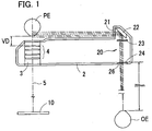
- Fig. 1 is a schematic sectional view of the optometric apparatus in a first embodiment.
- the optometric apparatus is provided with a pair of lens chamber units for examinations of a right and left eyes of an examinee.
- the lens chamber units are supported by a support unit not shown so that a test window 3 is adjusted to the height of an examinee's eye PE.
- Fig. 1 shows only a lens chamber unit 2 for a left eye examination (the eye PE is a left eye) and that a lens chamber unit for a right eye examination is simply symmetrically structured with respect to the left unit 2, and thus its detailed explanation is omitted.
- the right and left lens chamber units are supported by the support unit not shown so that an interval (distance) therebetween is adjustable in accordance with a pupillary distance between both eyes of the examinee.
- a plurality of optical elements 4 such as a spherical lens, a cylindrical lens to be used in a refractive power examination, and so on, are selectively disposed in the test window 3.
- the optical elements 4 are arranged (held) in rotary disks (not shown). By rotation of the rotary disks, a desired one of the optical elements 4 can be disposed in the test window 3.
- An examiner instructs the examinee to look at an examination optotype 10 presented forward of the eye PE through the optical element 4 disposed in the test window 3, the optotype 10 being placed on an examination optical axis 5.
- the examiner changes the optical element 4 according to how the optotype 10 visually appears.
- the refractive power of the eye PE can be examined.
- a cornea position alignment optical system 20 for determining a vertex distance VD between the back surface (facing the eye PE) of the optical element 4 (closest to the eye PE) and the corneal vertex of the eye PE.
- the alignment optical system 20 includes a reflection mirror 22 to be positioned at the side of the eye PE, an aligning scale plate 23 placed on an optical path in a direction that the mirror 22 reflects light, and a reticle plate 24. This reticle plate 24 is mounted in an observation window 26 formed in the lens chamber unit 2 at the front side (which faces the examiner).
- the examiner's eye OE being positioned at the front side of the lens chamber unit 2 can see the side of the eye PE through the mirror 22, the aligning scale plate 23, and the reticle plate 24.
- the lens chamber unit 2 further includes a window 21 to be placed between the eye PE and the mirror 22. It is to be noted that the aligning scale plate 23 may be placed in the window 21 or between the window 21 and the mirror 22 as in the conventional example.
- the alignment optical system 20 may also be provided in another unit, different from the lens chamber unit 2, as in the conventional example.
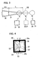
- Fig. 2A is a schematic structural view of the aligning scale plate 23 and Fig. 2B is a schematic structural view of the reticle plate 24.
- the scale plate 23 is marked with several thin lines S1 to S5 as a scale.
- the scale lines S1, S2, S3, S4, and S5 correspond to the vertex distances of 12 mm, 13.75 mm, 16 mm, 18 mm, and 20mm, respectively.
- the scale line S2 representing 13.75 mm which is a reference distance is drawn by a dotted line in order to distinguish it from other scale lines (solid lines).
- Two thick lines centrally-located and extended from above and below respectively are reference lines S6 for alignment in a horizontal direction.
- the aligning scale plate 23 is further marked with a first reference mark (target) 30. This first reference mark 30 is used to allow the examiner to adjust the position of his own eye OE to a point at a predetermined distance from the reticle plate 24, and it is formed of a rectangular frame line in the present embodiment.
- the reticle plate 24 includes a black-colored peripheral portion and a transparent inside portion.
- the reticle plate 24 is formed with two triangular reticles 24a of which respective apexes face each other on a center line of the reticle plate 24.
- the reticle plate 24 is also provided with a second reference mark (target) 31.
- This reference mark 31, which is used in combination with the first reference mark 30 of the aligning scale plate 23, is formed of a rectangular frame line like the first reference mark 30.
- the reticle plate 24 is also formed with numerical indices 25 representing vertex distances VD in the black-colored peripheral portion.
- the aligning scale plate 23, the scale lines S1 to S5, the reference lines S6, and the reticle plate 24 and the reticles 24a may be changed variously in shape and size.
- Fig. 3 is a view to explain a positional relation between the first reference mark 30 and the second reference mark 31 in order to allow the examiner to adjust the position of his eye OE to a point at a predetermined distance from the reticle plate 24.
- the sizes A and B of the first and second reference marks 30 and 31 are determined so that the marks 30 and 31 appear overlapped when the eye OE is positioned at a distance L of 250 mm from the reticle plate 24.
- the first reference mark 30 will appear positioned inside the second reference mark 31.
- the first reference mark 30 will appear positioned outside the second reference mark 31. Accordingly, if the position of the eye OE is adjusted so that the first and second reference marks 30 and 31 appear overlapped as a single mark, the examiner can accurately position his eye OE in a point P0 just at the distance L (250 mm).
- both the first and second reference marks 30 and 31 are provided as a rectangular frame line, so that vertical and horizontal alignment of these marks 30 and 31 allows the examiner to easily adjust his eye OE in a vertical and horizontal directions.
- the marks 30 and 31 may be formed of a circular frame line; that is, their shapes, line styles, etc. may be modified or changed variously. Furthermore, the marks 30 and 31 may have different colors to further improve their visibility. It is to be noted that the marks 30 and 31 may be provided anyplace on the optical path of the alignment optical system 20, not limited to the aligning scale plate 23 and the reticle plate 24.
- the examiner adjusts the position of his own eye OE while peeping through the observation window 26 to look at the reticle plate 24, until the second reference mark 31 of the reticle plate 24 appears overlapped, as a single mark, with the first reference mark 30 of the aligning scale plate 23. In this manner, the examiner can easily adjust his eye OE to a point at a distance L of 250 mm from the reticle plate 24.
- the examiner adjusts the position of his eye OE horizontally until the apexes of the reticles 24a appear aligned with the reference lines S6, as shown in Fig. 4, and then checks the position of the corneal vertex of the eye PE. If the eye PE has to be positioned to the point at a reference distance VD of 13.75 mm, the examiner moves a forehead rest not shown or the like to move the eye PE so that the corneal vertex appears to coincide with the scale line S2. If a person with sharply-chiseled features or a person with hollow eyes is examined, it is sometimes difficult to move his eye to the position at the reference distance.
- the examiner checks the position of the corneal vertex coincident with one of the other scale lines S1, S3 to S5 and determines the refractive power of the eye PE at the corresponding reference distance by using a predetermined conversion calculation based on the vertex distance VD.
- the position of the examinee's eye can be accurately and easily checked.
Landscapes
- Life Sciences & Earth Sciences (AREA)
- Health & Medical Sciences (AREA)
- Medical Informatics (AREA)
- Biophysics (AREA)
- Ophthalmology & Optometry (AREA)
- Engineering & Computer Science (AREA)
- Biomedical Technology (AREA)
- Heart & Thoracic Surgery (AREA)
- Physics & Mathematics (AREA)
- Molecular Biology (AREA)
- Surgery (AREA)
- Animal Behavior & Ethology (AREA)
- General Health & Medical Sciences (AREA)
- Public Health (AREA)
- Veterinary Medicine (AREA)
- Eye Examination Apparatus (AREA)
Description
- The present invention relates to an optometric apparatus for subjectively examining visual functions of an examinee's eye.
- A vertex distance VD (visual distance) between a back surface of a lens of spectacles which an examinee puts on (namely, a lens wearing reference point) and a corneal vertex of an examinee's eye is generally considered to be 13.75 mm or 12.00 mm in a reference distance. Accordingly, in an optometric apparatus adapted such that various kinds of optical elements are selectively disposed in a test window to present various kinds of optotypes through the test window in order to subjective examination of visual functions such as a refracting power of the examinee's eye and the like, the vertex distance VD between the lens (optical element) back surface and the corneal vertex needs to be checked. Thus, this type of optometric apparatus is provided with a cornea position alignment optical system for allowing check of the vertex distance VD.
- Fig. 5 is a schematic sectional view of the cornea position alignment optical system provided in a conventional optometric apparatus. Various kinds of
optical elements 104 are selectively disposed in atest window 103 of alens chamber unit 100, so that the examinee's eye PE is allowed to look at anoptotype 110 forward presented through theoptical element 104. Thelens chamber unit 100 is attached (or is separately provided) with analigning unit 125 in which a cornea position alignmentoptical system 120 is mounted. This alignmentoptical system 120 is constructed of an aligningscale plate 121 placed to be positioned at the side of the eye PE during examinations, areflection mirror 122, and areticle plate 123 placed on an optical path in a direction that themirror 122 reflects light. An examiner takes his position at a distance of 250 mm from thereticle plate 123 and then goes into position so thattriangular reticles 124 provided on thereticle plate 123 appears visually aligned with a long scale line S1 provided on the aligningscale plate 121, as shown in Fig. 6. Then, the examiner checks the positional relation of the long line S1 and a plurality of short scale lines S2, formed on both sides of the long line S1, with respect to the corneal vertex. For example, if the corneal vertex appears to coincide with the long line S1, the vertex distance VD is a reference distance of 13.75 mm. The short lines S2 are spaced at intervals corresponding to several vertex distances. According to which short line S2 (or long line S1) the corneal vertex coincides with, the vertex distance VD can be checked (determined). One example of the optometric apparatus provided with the cornea position aligning system of the above type is disclosed in for exampleJapanese patent unexamined publication No. Hei 6-181888 - In the above mentioned cornea position aligning system, however, an eye OE of the examiner has to be substantially accurately positioned in a place 250 mm apart from the
reticle plate 123; otherwise, the checked vertex distance VD would include considerable errors. If the vertex distance VD is incorrect, the results of the refractive power examination or the like would also have errors. -
JP05-16 8595 - The present invention has been made in view of the above circumstances and has an object to overcome the above problems and to provide an optometric apparatus which allows accurate and easy check of a position of an examinee's eye.
- Additional objects and advantages of the invention will be set forth in part in the description which follows and in part will be obvious from the description, or may be learned by practice of the invention. The objects and advantages of the invention may be realized and attained by means of the instrumentalities and combinations particularly pointed out in the appended claims.
- Such objects are achieved in accordance with an optometric apparatus comprising the features of claim 1. More specifically, the present invention provides an optometric apparatus for subjectively examining visual functions of an eye of an examinee, the apparatus including: disposing means for disposing an optical element in front of the examinee's eye; a cornea position alignment optical system for checking a vertex distance between a back surface of the disposed optical element and a corneal vertex of the examinee's eye; wherein the alignment optical system includes an aligning scale plate provided with a scale for checking the vertex distance, a reticle plate provided with a reticle and placed in a different place from the aligning scale plate, and a first reference mark and a second reference mark for positioning an eye of an examiner in a point at a predetermined distance from the reticle plate, the first and second reference marks being provided in different places and appearing, to the examiner's eye, to have a predetermined positional relation with each other when the examiner's eye is positioned in the point at the predetermined distance from the reticle plate.
- Further developments of the present invention are given in the dependent claims.
- The accompanying drawings, which are incorporated in and constitute a part of this specification illustrate an embodiment of the invention and, together with the description, serve to explain the objects, advantages and principles of the invention.
- In the drawings,
- Fig. 1 is a schematic sectional view of an optometric apparatus in a first embodiment according to the present invention;
- Figs. 2A and 2B are schematic structural views of an aligning scale plate and a reticle plate;
- Fig. 3 is a view to explain a positional relation between a first reference mark and a second reference mark for positioning an examinee's eye in a point at a predetermined distance from a reticle plate;
- Fig. 4 is a view to explain the case that an examiner positions his eye in a point where an apex of a reticle appears aligned with a reference line and then a position of a corneal vertex of the examinee's eye is checked;
- Fig. 5 is a schematic sectional view of a cornea position alignment optical system provided in a conventional optometric apparatus; and
- Fig. 6 is a view to explain the case that an examiner positions his eye in a point where a reticle of the reticle plate appears aligned with a long scale line S1 of the aligning scale plate, and then a position of a corneal vertex of an examinee's eye is checked.
- A detailed description of preferred embodiments of an optometric apparatus embodying the present invention will now be given referring to the accompanying drawings. Fig. 1 is a schematic sectional view of the optometric apparatus in a first embodiment. The optometric apparatus is provided with a pair of lens chamber units for examinations of a right and left eyes of an examinee. The lens chamber units are supported by a support unit not shown so that a
test window 3 is adjusted to the height of an examinee's eye PE. It is to be noted that Fig. 1 shows only alens chamber unit 2 for a left eye examination (the eye PE is a left eye) and that a lens chamber unit for a right eye examination is simply symmetrically structured with respect to theleft unit 2, and thus its detailed explanation is omitted. The right and left lens chamber units are supported by the support unit not shown so that an interval (distance) therebetween is adjustable in accordance with a pupillary distance between both eyes of the examinee. - In the
lens chamber unit 2, there are provided a plurality ofoptical elements 4 such as a spherical lens, a cylindrical lens to be used in a refractive power examination, and so on, are selectively disposed in thetest window 3. Theoptical elements 4 are arranged (held) in rotary disks (not shown). By rotation of the rotary disks, a desired one of theoptical elements 4 can be disposed in thetest window 3. - An examiner instructs the examinee to look at an
examination optotype 10 presented forward of the eye PE through theoptical element 4 disposed in thetest window 3, theoptotype 10 being placed on an examinationoptical axis 5. The examiner changes theoptical element 4 according to how theoptotype 10 visually appears. Thus, the refractive power of the eye PE can be examined. - In the
lens chamber unit 2, furthermore, a cornea position alignmentoptical system 20 for determining a vertex distance VD between the back surface (facing the eye PE) of the optical element 4 (closest to the eye PE) and the corneal vertex of the eye PE. The alignmentoptical system 20 includes areflection mirror 22 to be positioned at the side of the eye PE, an aligningscale plate 23 placed on an optical path in a direction that themirror 22 reflects light, and areticle plate 24. Thisreticle plate 24 is mounted in anobservation window 26 formed in thelens chamber unit 2 at the front side (which faces the examiner). The examiner's eye OE being positioned at the front side of thelens chamber unit 2 can see the side of the eye PE through themirror 22, the aligningscale plate 23, and thereticle plate 24. Thelens chamber unit 2 further includes awindow 21 to be placed between the eye PE and themirror 22. It is to be noted that the aligningscale plate 23 may be placed in thewindow 21 or between thewindow 21 and themirror 22 as in the conventional example. The alignmentoptical system 20 may also be provided in another unit, different from thelens chamber unit 2, as in the conventional example. - Fig. 2A is a schematic structural view of the aligning
scale plate 23 and Fig. 2B is a schematic structural view of thereticle plate 24. Thescale plate 23 is marked with several thin lines S1 to S5 as a scale. The scale lines S1, S2, S3, S4, and S5 correspond to the vertex distances of 12 mm, 13.75 mm, 16 mm, 18 mm, and 20mm, respectively. The scale line S2 representing 13.75 mm which is a reference distance is drawn by a dotted line in order to distinguish it from other scale lines (solid lines). Two thick lines centrally-located and extended from above and below respectively are reference lines S6 for alignment in a horizontal direction. The aligningscale plate 23 is further marked with a first reference mark (target) 30. Thisfirst reference mark 30 is used to allow the examiner to adjust the position of his own eye OE to a point at a predetermined distance from thereticle plate 24, and it is formed of a rectangular frame line in the present embodiment. - The
reticle plate 24 includes a black-colored peripheral portion and a transparent inside portion. Thereticle plate 24 is formed with twotriangular reticles 24a of which respective apexes face each other on a center line of thereticle plate 24. Thereticle plate 24 is also provided with a second reference mark (target) 31. Thisreference mark 31, which is used in combination with thefirst reference mark 30 of the aligningscale plate 23, is formed of a rectangular frame line like thefirst reference mark 30. Thereticle plate 24 is also formed withnumerical indices 25 representing vertex distances VD in the black-colored peripheral portion. - It is to be noted that the aligning
scale plate 23, the scale lines S1 to S5, the reference lines S6, and thereticle plate 24 and thereticles 24a may be changed variously in shape and size. - Fig. 3 is a view to explain a positional relation between the
first reference mark 30 and thesecond reference mark 31 in order to allow the examiner to adjust the position of his eye OE to a point at a predetermined distance from thereticle plate 24. The sizes A and B of the first and second reference marks 30 and 31 are determined so that themarks reticle plate 24. In other words, assuming that the size of thefirst reference mark 30 is "A", the size of thesecond reference mark 31 is "B", the design distance between thesecond reference mark 31 of thereticle plate 24 and the position at which the eye OE is to be positioned is "L (250 mm)", and the distance between the first and second reference marks 30 and 31 is "ΔL", the sizes A and B are determined so that the following relation is established:
- In the case where the eye OE is positioned in a point P1 at a shorter distance than the distance L (250 mm), the
first reference mark 30 will appear positioned inside thesecond reference mark 31. On the other hand, in the case where the eye OE is positioned in a point P2 at a longer distance than the distance L (250 mm), thefirst reference mark 30 will appear positioned outside thesecond reference mark 31. Accordingly, if the position of the eye OE is adjusted so that the first and second reference marks 30 and 31 appear overlapped as a single mark, the examiner can accurately position his eye OE in a point P0 just at the distance L (250 mm). - In the present embodiment, both the first and second reference marks 30 and 31 are provided as a rectangular frame line, so that vertical and horizontal alignment of these
marks marks marks marks optical system 20, not limited to the aligningscale plate 23 and thereticle plate 24. - To check the position of the corneal vertex (i.e., the vertex distance VD) of the eye PE, the examiner adjusts the position of his own eye OE while peeping through the
observation window 26 to look at thereticle plate 24, until thesecond reference mark 31 of thereticle plate 24 appears overlapped, as a single mark, with thefirst reference mark 30 of the aligningscale plate 23. In this manner, the examiner can easily adjust his eye OE to a point at a distance L of 250 mm from thereticle plate 24. - Thereafter, the examiner adjusts the position of his eye OE horizontally until the apexes of the
reticles 24a appear aligned with the reference lines S6, as shown in Fig. 4, and then checks the position of the corneal vertex of the eye PE. If the eye PE has to be positioned to the point at a reference distance VD of 13.75 mm, the examiner moves a forehead rest not shown or the like to move the eye PE so that the corneal vertex appears to coincide with the scale line S2. If a person with sharply-chiseled features or a person with hollow eyes is examined, it is sometimes difficult to move his eye to the position at the reference distance. In this case, the examiner checks the position of the corneal vertex coincident with one of the other scale lines S1, S3 to S5 and determines the refractive power of the eye PE at the corresponding reference distance by using a predetermined conversion calculation based on the vertex distance VD. - According to the present invention, as described above, the position of the examinee's eye can be accurately and easily checked.
- While the presently preferred embodiment of the present invention has been shown and described, it is to be understood that this disclosure is for the purpose of illustration and that various changes and modifications may be made without departing from the scope of the invention as set forth in the appended claims.
Claims (4)
- An optometric apparatus for subjectively examining visual functions of an eye (PE) of an examinee, the apparatus including:disposing means (2) which disposes an optical element (4) in front of the examinee's eye;a cornea position alignment optical system (20) arranged to check a vertex distance between a back surface of the disposed optical element and a corneal vertex of the examinee's eye;wherein the alignment optical system (20) includes an aligning scale plate (23) provided with a scale (S1-S5) arranged to check the vertex distance, and a reticle plate (24) provided with a reticle (24a) and placed in a different place from the aligning scale plate,characterized in thatthe alignment optical system (20) comprises a first reference mark (30) and a second reference mark (31) in the two-dimensional shape of a rectangular or circular frame line, which are marks provided in different places of the optical path of the alignement optical system (20) to have a predetermined positional relation with each other when observed by an eye of an examiner who is in a position at a predetermined distance from the reticle plate (24).
- The optometric apparatus according to claim 1, wherein the first reference mark is formed on the aligning scale plate, and the second reference mark is formed on the reticle plate.
- The optometric apparatus according to claim 1, wherein shapes and positions of the first and second reference marks are determined so that the reference marks are to be observed in coincident relation by the eye of the examiner who is in the position at the predetermined distance from the reticle plate (24).
- The optometric apparatus according to claim 1, wherein the aligning scale plate has a mark (S6) for horizontal alignment of the examiner's eye with respect to the reticle.
Applications Claiming Priority (2)
| Application Number | Priority Date | Filing Date | Title |
|---|---|---|---|
| JP2003019631A JP3899039B2 (en) | 2003-01-29 | 2003-01-29 | Optometry equipment |
| JP2003019631 | 2003-01-29 |
Publications (2)
| Publication Number | Publication Date |
|---|---|
| EP1442696A1 EP1442696A1 (en) | 2004-08-04 |
| EP1442696B1 true EP1442696B1 (en) | 2007-09-19 |
Family
ID=32652859
Family Applications (1)
| Application Number | Title | Priority Date | Filing Date |
|---|---|---|---|
| EP04001826A Expired - Lifetime EP1442696B1 (en) | 2003-01-29 | 2004-01-28 | Optometric apparatus |
Country Status (4)
| Country | Link |
|---|---|
| US (1) | US7073907B2 (en) |
| EP (1) | EP1442696B1 (en) |
| JP (1) | JP3899039B2 (en) |
| DE (1) | DE602004008976T2 (en) |
Families Citing this family (8)
| Publication number | Priority date | Publication date | Assignee | Title |
|---|---|---|---|---|
| JP4628795B2 (en) * | 2005-01-05 | 2011-02-09 | 株式会社ニデック | Optometry equipment |
| EP2560543B1 (en) * | 2010-04-22 | 2018-08-01 | Massachusetts Institute of Technology | Near eye tool for refractive assessment |
| KR101374173B1 (en) * | 2013-08-27 | 2014-03-13 | 유니코스주식회사 | Lensmeter for vertex distance adjustable and vertex distance adjust method |
| CN105942971A (en) * | 2016-06-25 | 2016-09-21 | 宁波明星科技发展有限公司 | Full-automatic comprehensive optometry unit |
| JP6930095B2 (en) | 2016-12-01 | 2021-09-01 | 株式会社ニデック | Subjective optometry device |
| JP7162480B2 (en) * | 2018-09-26 | 2022-10-28 | 株式会社トプコン | Optometry equipment |
| JP7443831B2 (en) | 2020-03-04 | 2024-03-06 | 株式会社ニデック | Optometry systems, optometry controllers, and optometry programs |
| WO2021200605A1 (en) | 2020-03-31 | 2021-10-07 | 株式会社ニデック | Optometry system, optometry controller, and optometry program |
Family Cites Families (10)
| Publication number | Priority date | Publication date | Assignee | Title |
|---|---|---|---|---|
| US2063015A (en) * | 1932-06-20 | 1936-12-08 | Dartmouth College | Eye testing instrument |
| US2081969A (en) * | 1933-07-03 | 1937-06-01 | Clile C Allen | Instrument for examining the eyes |
| US2290864A (en) * | 1941-09-20 | 1942-07-28 | Joseph H Church | Range finder |
| US3536384A (en) * | 1968-07-05 | 1970-10-27 | Battelle Development Corp | Apparatus for determining corneal curvature and the like |
| US3664730A (en) * | 1970-10-15 | 1972-05-23 | Hernando Cardona | Ophthalmoscope |
| US3904280A (en) * | 1973-12-28 | 1975-09-09 | Clegg Jr Giles C | Method and apparatus for determining the distance between the surface of an eye and a reference point |
| JP2933313B2 (en) | 1988-08-15 | 1999-08-09 | 株式会社トプコン | Subjective optometer |
| JP3165207B2 (en) | 1991-12-25 | 2001-05-14 | ホーヤ株式会社 | Vertex adjustment device of optometer |
| US5463430A (en) * | 1992-07-31 | 1995-10-31 | Nidek Co., Ltd. | Examination apparatus for examining an object having a spheroidal reflective surface |
| JP3311054B2 (en) | 1992-12-15 | 2002-08-05 | 株式会社トーメー | Subjective optometry device |
-
2003
- 2003-01-29 JP JP2003019631A patent/JP3899039B2/en not_active Expired - Fee Related
-
2004
- 2004-01-26 US US10/763,437 patent/US7073907B2/en active Active
- 2004-01-28 DE DE602004008976T patent/DE602004008976T2/en not_active Expired - Lifetime
- 2004-01-28 EP EP04001826A patent/EP1442696B1/en not_active Expired - Lifetime
Also Published As
| Publication number | Publication date |
|---|---|
| US20040207812A1 (en) | 2004-10-21 |
| JP3899039B2 (en) | 2007-03-28 |
| US7073907B2 (en) | 2006-07-11 |
| DE602004008976D1 (en) | 2007-10-31 |
| DE602004008976T2 (en) | 2008-01-17 |
| EP1442696A1 (en) | 2004-08-04 |
| JP2004229769A (en) | 2004-08-19 |
Similar Documents
| Publication | Publication Date | Title |
|---|---|---|
| EP1444945B1 (en) | Optometric device | |
| US5255025A (en) | Measurement apparatus for indirect ophthalmoscopy | |
| JP4252902B2 (en) | Optometry apparatus and optometry chart | |
| US7976161B2 (en) | Method and system to assess objectively visual characteristics | |
| US7384147B1 (en) | Apparatus and method for ophthalmometery | |
| US6132045A (en) | Eyeglass frame fitting apparatus, kit and method | |
| EP1442696B1 (en) | Optometric apparatus | |
| US20210330186A1 (en) | Portable screening devices and systems for remote opthalmic diagnostics | |
| CN110476108B (en) | Method for designing a pair of ophthalmic lenses and apparatus for optical measurement | |
| EP3903663A1 (en) | Refractive property measurement device, measurement tool, and refractive property measurement method | |
| CA2080668C (en) | Rectilinear photokeratoscope | |
| ES2942865T3 (en) | Determination of values for myopia control of one eye of a user | |
| JPH09253049A (en) | Ophthalmometer | |
| CN113208554A (en) | Optometry device with defocusing and astigmatism accurate correction functions and optometry method | |
| JP2567642B2 (en) | Pupillary distance meter | |
| JPH06121773A (en) | Ophthalmology refractometer | |
| JP3542215B2 (en) | Perimeter | |
| JP2019062936A (en) | Ophthalmologic apparatus | |
| CA2023875C (en) | Ophthalmic prismatic image relocating eye glasses for persons having retinitis pigmentosa and hemianopia and method for making same | |
| JP3575825B2 (en) | Ophthalmic equipment | |
| JP2004166903A (en) | Optometric device | |
| JPH09271461A (en) | Ophthalmometer | |
| EP0587964B1 (en) | Instrument for centering corrective lenses | |
| JP2002017672A (en) | Optometrical instrument | |
| WO2020086693A1 (en) | Portable screening devices and systems for remote opthalmic diagnostics |
Legal Events
| Date | Code | Title | Description |
|---|---|---|---|
| PUAI | Public reference made under article 153(3) epc to a published international application that has entered the european phase |
Free format text: ORIGINAL CODE: 0009012 |
|
| AK | Designated contracting states |
Kind code of ref document: A1 Designated state(s): AT BE BG CH CY CZ DE DK EE ES FI FR GB GR HU IE IT LI LU MC NL PT RO SE SI SK TR |
|
| AX | Request for extension of the european patent |
Extension state: AL LT LV MK |
|
| 17P | Request for examination filed |
Effective date: 20041227 |
|
| AKX | Designation fees paid |
Designated state(s): DE FR GB |
|
| 17Q | First examination report despatched |
Effective date: 20050603 |
|
| 17Q | First examination report despatched |
Effective date: 20050603 |
|
| GRAP | Despatch of communication of intention to grant a patent |
Free format text: ORIGINAL CODE: EPIDOSNIGR1 |
|
| GRAS | Grant fee paid |
Free format text: ORIGINAL CODE: EPIDOSNIGR3 |
|
| GRAA | (expected) grant |
Free format text: ORIGINAL CODE: 0009210 |
|
| AK | Designated contracting states |
Kind code of ref document: B1 Designated state(s): DE FR GB |
|
| REG | Reference to a national code |
Ref country code: GB Ref legal event code: FG4D |
|
| REF | Corresponds to: |
Ref document number: 602004008976 Country of ref document: DE Date of ref document: 20071031 Kind code of ref document: P |
|
| ET | Fr: translation filed | ||
| PLBE | No opposition filed within time limit |
Free format text: ORIGINAL CODE: 0009261 |
|
| STAA | Information on the status of an ep patent application or granted ep patent |
Free format text: STATUS: NO OPPOSITION FILED WITHIN TIME LIMIT |
|
| 26N | No opposition filed |
Effective date: 20080620 |
|
| PGFP | Annual fee paid to national office [announced via postgrant information from national office to epo] |
Ref country code: GB Payment date: 20090128 Year of fee payment: 6 |
|
| GBPC | Gb: european patent ceased through non-payment of renewal fee |
Effective date: 20100128 |
|
| PG25 | Lapsed in a contracting state [announced via postgrant information from national office to epo] |
Ref country code: GB Free format text: LAPSE BECAUSE OF NON-PAYMENT OF DUE FEES Effective date: 20100128 |
|
| REG | Reference to a national code |
Ref country code: FR Ref legal event code: PLFP Year of fee payment: 13 |
|
| REG | Reference to a national code |
Ref country code: FR Ref legal event code: PLFP Year of fee payment: 14 |
|
| REG | Reference to a national code |
Ref country code: FR Ref legal event code: PLFP Year of fee payment: 15 |
|
| PGFP | Annual fee paid to national office [announced via postgrant information from national office to epo] |
Ref country code: DE Payment date: 20211207 Year of fee payment: 19 |
|
| PGFP | Annual fee paid to national office [announced via postgrant information from national office to epo] |
Ref country code: FR Payment date: 20221208 Year of fee payment: 20 |
|
| P01 | Opt-out of the competence of the unified patent court (upc) registered |
Effective date: 20230509 |
|
| REG | Reference to a national code |
Ref country code: DE Ref legal event code: R119 Ref document number: 602004008976 Country of ref document: DE |
|
| PG25 | Lapsed in a contracting state [announced via postgrant information from national office to epo] |
Ref country code: DE Free format text: LAPSE BECAUSE OF NON-PAYMENT OF DUE FEES Effective date: 20230801 |