EP0587785B1 - Schnell auskuppelbare Kupplung für dreiteilige Rotoren in kontinuierlichen Mischern für plastische Materialien - Google Patents
Schnell auskuppelbare Kupplung für dreiteilige Rotoren in kontinuierlichen Mischern für plastische Materialien Download PDFInfo
- Publication number
- EP0587785B1 EP0587785B1 EP92913804A EP92913804A EP0587785B1 EP 0587785 B1 EP0587785 B1 EP 0587785B1 EP 92913804 A EP92913804 A EP 92913804A EP 92913804 A EP92913804 A EP 92913804A EP 0587785 B1 EP0587785 B1 EP 0587785B1
- Authority
- EP
- European Patent Office
- Prior art keywords
- quick
- pilot
- main rotor
- plug
- rotor body
- Prior art date
- Legal status (The legal status is an assumption and is not a legal conclusion. Google has not performed a legal analysis and makes no representation as to the accuracy of the status listed.)
- Expired - Lifetime
Links
- 230000008878 coupling Effects 0.000 title claims abstract description 61
- 238000010168 coupling process Methods 0.000 title claims abstract description 61
- 238000005859 coupling reaction Methods 0.000 title claims abstract description 61
- 239000004033 plastic Substances 0.000 title claims abstract description 31
- 239000000463 material Substances 0.000 title claims abstract description 30
- 230000013011 mating Effects 0.000 claims description 6
- 238000003780 insertion Methods 0.000 claims description 2
- 230000037431 insertion Effects 0.000 claims description 2
- 238000009434 installation Methods 0.000 claims description 2
- 230000036316 preload Effects 0.000 claims 1
- 230000000712 assembly Effects 0.000 abstract description 14
- 238000000429 assembly Methods 0.000 abstract description 14
- 238000000926 separation method Methods 0.000 abstract description 3
- 238000001816 cooling Methods 0.000 description 37
- 238000002156 mixing Methods 0.000 description 32
- 239000002826 coolant Substances 0.000 description 25
- 238000011144 upstream manufacturing Methods 0.000 description 21
- 238000002955 isolation Methods 0.000 description 18
- 230000007935 neutral effect Effects 0.000 description 14
- 241000239290 Araneae Species 0.000 description 8
- 238000009413 insulation Methods 0.000 description 7
- 230000003416 augmentation Effects 0.000 description 6
- 239000004519 grease Substances 0.000 description 6
- 238000012423 maintenance Methods 0.000 description 6
- 238000012856 packing Methods 0.000 description 6
- 230000009471 action Effects 0.000 description 5
- 238000001125 extrusion Methods 0.000 description 5
- 230000007246 mechanism Effects 0.000 description 5
- 230000005540 biological transmission Effects 0.000 description 4
- 239000003638 chemical reducing agent Substances 0.000 description 4
- 239000007788 liquid Substances 0.000 description 4
- 238000000034 method Methods 0.000 description 4
- 125000006850 spacer group Chemical group 0.000 description 4
- XLYOFNOQVPJJNP-UHFFFAOYSA-N water Substances O XLYOFNOQVPJJNP-UHFFFAOYSA-N 0.000 description 4
- 238000005461 lubrication Methods 0.000 description 3
- 239000000654 additive Substances 0.000 description 2
- 230000008901 benefit Effects 0.000 description 2
- 230000006835 compression Effects 0.000 description 2
- 238000007906 compression Methods 0.000 description 2
- 238000007667 floating Methods 0.000 description 2
- 210000004907 gland Anatomy 0.000 description 2
- 239000004615 ingredient Substances 0.000 description 2
- 239000000203 mixture Substances 0.000 description 2
- 238000012986 modification Methods 0.000 description 2
- 230000004048 modification Effects 0.000 description 2
- 229910000831 Steel Inorganic materials 0.000 description 1
- 239000012080 ambient air Substances 0.000 description 1
- 230000003190 augmentative effect Effects 0.000 description 1
- 238000005452 bending Methods 0.000 description 1
- 239000000919 ceramic Substances 0.000 description 1
- 230000008859 change Effects 0.000 description 1
- 239000010724 circulating oil Substances 0.000 description 1
- 238000004140 cleaning Methods 0.000 description 1
- 239000003086 colorant Substances 0.000 description 1
- 238000013329 compounding Methods 0.000 description 1
- 230000008602 contraction Effects 0.000 description 1
- 230000001276 controlling effect Effects 0.000 description 1
- 238000007599 discharging Methods 0.000 description 1
- 239000000945 filler Substances 0.000 description 1
- 230000005484 gravity Effects 0.000 description 1
- 239000012774 insulation material Substances 0.000 description 1
- 239000012212 insulator Substances 0.000 description 1
- 230000001050 lubricating effect Effects 0.000 description 1
- 239000003921 oil Substances 0.000 description 1
- 238000009428 plumbing Methods 0.000 description 1
- 238000012545 processing Methods 0.000 description 1
- 238000005086 pumping Methods 0.000 description 1
- 230000001105 regulatory effect Effects 0.000 description 1
- 229910001220 stainless steel Inorganic materials 0.000 description 1
- 239000010935 stainless steel Substances 0.000 description 1
- 239000010959 steel Substances 0.000 description 1
- 238000013022 venting Methods 0.000 description 1
- 239000003039 volatile agent Substances 0.000 description 1
Images




Classifications
-
- B—PERFORMING OPERATIONS; TRANSPORTING
- B29—WORKING OF PLASTICS; WORKING OF SUBSTANCES IN A PLASTIC STATE IN GENERAL
- B29B—PREPARATION OR PRETREATMENT OF THE MATERIAL TO BE SHAPED; MAKING GRANULES OR PREFORMS; RECOVERY OF PLASTICS OR OTHER CONSTITUENTS OF WASTE MATERIAL CONTAINING PLASTICS
- B29B7/00—Mixing; Kneading
- B29B7/30—Mixing; Kneading continuous, with mechanical mixing or kneading devices
- B29B7/34—Mixing; Kneading continuous, with mechanical mixing or kneading devices with movable mixing or kneading devices
- B29B7/38—Mixing; Kneading continuous, with mechanical mixing or kneading devices with movable mixing or kneading devices rotary
- B29B7/46—Mixing; Kneading continuous, with mechanical mixing or kneading devices with movable mixing or kneading devices rotary with more than one shaft
- B29B7/48—Mixing; Kneading continuous, with mechanical mixing or kneading devices with movable mixing or kneading devices rotary with more than one shaft with intermeshing devices, e.g. screws
-
- F—MECHANICAL ENGINEERING; LIGHTING; HEATING; WEAPONS; BLASTING
- F16—ENGINEERING ELEMENTS AND UNITS; GENERAL MEASURES FOR PRODUCING AND MAINTAINING EFFECTIVE FUNCTIONING OF MACHINES OR INSTALLATIONS; THERMAL INSULATION IN GENERAL
- F16D—COUPLINGS FOR TRANSMITTING ROTATION; CLUTCHES; BRAKES
- F16D1/00—Couplings for rigidly connecting two coaxial shafts or other movable machine elements
- F16D1/02—Couplings for rigidly connecting two coaxial shafts or other movable machine elements for connecting two abutting shafts or the like
- F16D1/033—Couplings for rigidly connecting two coaxial shafts or other movable machine elements for connecting two abutting shafts or the like by clamping together two faces perpendicular to the axis of rotation, e.g. with bolted flanges
-
- B—PERFORMING OPERATIONS; TRANSPORTING
- B29—WORKING OF PLASTICS; WORKING OF SUBSTANCES IN A PLASTIC STATE IN GENERAL
- B29B—PREPARATION OR PRETREATMENT OF THE MATERIAL TO BE SHAPED; MAKING GRANULES OR PREFORMS; RECOVERY OF PLASTICS OR OTHER CONSTITUENTS OF WASTE MATERIAL CONTAINING PLASTICS
- B29B7/00—Mixing; Kneading
- B29B7/30—Mixing; Kneading continuous, with mechanical mixing or kneading devices
- B29B7/34—Mixing; Kneading continuous, with mechanical mixing or kneading devices with movable mixing or kneading devices
- B29B7/38—Mixing; Kneading continuous, with mechanical mixing or kneading devices with movable mixing or kneading devices rotary
- B29B7/46—Mixing; Kneading continuous, with mechanical mixing or kneading devices with movable mixing or kneading devices rotary with more than one shaft
- B29B7/48—Mixing; Kneading continuous, with mechanical mixing or kneading devices with movable mixing or kneading devices rotary with more than one shaft with intermeshing devices, e.g. screws
- B29B7/488—Parts, e.g. casings, sealings; Accessories, e.g. flow controlling or throttling devices
-
- B—PERFORMING OPERATIONS; TRANSPORTING
- B29—WORKING OF PLASTICS; WORKING OF SUBSTANCES IN A PLASTIC STATE IN GENERAL
- B29C—SHAPING OR JOINING OF PLASTICS; SHAPING OF MATERIAL IN A PLASTIC STATE, NOT OTHERWISE PROVIDED FOR; AFTER-TREATMENT OF THE SHAPED PRODUCTS, e.g. REPAIRING
- B29C48/00—Extrusion moulding, i.e. expressing the moulding material through a die or nozzle which imparts the desired form; Apparatus therefor
- B29C48/25—Component parts, details or accessories; Auxiliary operations
- B29C48/36—Means for plasticising or homogenising the moulding material or forcing it through the nozzle or die
- B29C48/375—Plasticisers, homogenisers or feeders comprising two or more stages
- B29C48/39—Plasticisers, homogenisers or feeders comprising two or more stages a first extruder feeding the melt into an intermediate location of a second extruder
-
- B—PERFORMING OPERATIONS; TRANSPORTING
- B29—WORKING OF PLASTICS; WORKING OF SUBSTANCES IN A PLASTIC STATE IN GENERAL
- B29C—SHAPING OR JOINING OF PLASTICS; SHAPING OF MATERIAL IN A PLASTIC STATE, NOT OTHERWISE PROVIDED FOR; AFTER-TREATMENT OF THE SHAPED PRODUCTS, e.g. REPAIRING
- B29C48/00—Extrusion moulding, i.e. expressing the moulding material through a die or nozzle which imparts the desired form; Apparatus therefor
- B29C48/25—Component parts, details or accessories; Auxiliary operations
- B29C48/36—Means for plasticising or homogenising the moulding material or forcing it through the nozzle or die
- B29C48/395—Means for plasticising or homogenising the moulding material or forcing it through the nozzle or die using screws surrounded by a cooperating barrel, e.g. single screw extruders
- B29C48/40—Means for plasticising or homogenising the moulding material or forcing it through the nozzle or die using screws surrounded by a cooperating barrel, e.g. single screw extruders using two or more parallel screws or at least two parallel non-intermeshing screws, e.g. twin screw extruders
-
- B—PERFORMING OPERATIONS; TRANSPORTING
- B29—WORKING OF PLASTICS; WORKING OF SUBSTANCES IN A PLASTIC STATE IN GENERAL
- B29C—SHAPING OR JOINING OF PLASTICS; SHAPING OF MATERIAL IN A PLASTIC STATE, NOT OTHERWISE PROVIDED FOR; AFTER-TREATMENT OF THE SHAPED PRODUCTS, e.g. REPAIRING
- B29C48/00—Extrusion moulding, i.e. expressing the moulding material through a die or nozzle which imparts the desired form; Apparatus therefor
- B29C48/25—Component parts, details or accessories; Auxiliary operations
- B29C48/36—Means for plasticising or homogenising the moulding material or forcing it through the nozzle or die
- B29C48/50—Details of extruders
- B29C48/505—Screws
- B29C48/67—Screws having incorporated mixing devices not provided for in groups B29C48/52 - B29C48/66
-
- Y—GENERAL TAGGING OF NEW TECHNOLOGICAL DEVELOPMENTS; GENERAL TAGGING OF CROSS-SECTIONAL TECHNOLOGIES SPANNING OVER SEVERAL SECTIONS OF THE IPC; TECHNICAL SUBJECTS COVERED BY FORMER USPC CROSS-REFERENCE ART COLLECTIONS [XRACs] AND DIGESTS
- Y10—TECHNICAL SUBJECTS COVERED BY FORMER USPC
- Y10T—TECHNICAL SUBJECTS COVERED BY FORMER US CLASSIFICATION
- Y10T403/00—Joints and connections
- Y10T403/57—Distinct end coupler
-
- Y—GENERAL TAGGING OF NEW TECHNOLOGICAL DEVELOPMENTS; GENERAL TAGGING OF CROSS-SECTIONAL TECHNOLOGIES SPANNING OVER SEVERAL SECTIONS OF THE IPC; TECHNICAL SUBJECTS COVERED BY FORMER USPC CROSS-REFERENCE ART COLLECTIONS [XRACs] AND DIGESTS
- Y10—TECHNICAL SUBJECTS COVERED BY FORMER USPC
- Y10T—TECHNICAL SUBJECTS COVERED BY FORMER US CLASSIFICATION
- Y10T403/00—Joints and connections
- Y10T403/57—Distinct end coupler
- Y10T403/5706—Diverse serial connections
-
- Y—GENERAL TAGGING OF NEW TECHNOLOGICAL DEVELOPMENTS; GENERAL TAGGING OF CROSS-SECTIONAL TECHNOLOGIES SPANNING OVER SEVERAL SECTIONS OF THE IPC; TECHNICAL SUBJECTS COVERED BY FORMER USPC CROSS-REFERENCE ART COLLECTIONS [XRACs] AND DIGESTS
- Y10—TECHNICAL SUBJECTS COVERED BY FORMER USPC
- Y10T—TECHNICAL SUBJECTS COVERED BY FORMER US CLASSIFICATION
- Y10T403/00—Joints and connections
- Y10T403/67—Thimble: screw or cam
-
- Y—GENERAL TAGGING OF NEW TECHNOLOGICAL DEVELOPMENTS; GENERAL TAGGING OF CROSS-SECTIONAL TECHNOLOGIES SPANNING OVER SEVERAL SECTIONS OF THE IPC; TECHNICAL SUBJECTS COVERED BY FORMER USPC CROSS-REFERENCE ART COLLECTIONS [XRACs] AND DIGESTS
- Y10—TECHNICAL SUBJECTS COVERED BY FORMER USPC
- Y10T—TECHNICAL SUBJECTS COVERED BY FORMER US CLASSIFICATION
- Y10T403/00—Joints and connections
- Y10T403/70—Interfitted members
- Y10T403/7016—Diametric end slot is joint component
Definitions
- the present invention is in the field of two-rotor continuous mixers for plastic materials. More particularly, this invention relates to quick-disconnect couplings which enable a main rotor body section of a three-piece rotor to be quickly and conveniently uncoupled from its drive journal located at one end of the main rotor body and its driven journal located at the other end of the rotor body. After uncoupling, the main rotor body of each rotor can be lifted away from an opened barrel of the continuous mixer.
- three-piece rotors for use in two-rotor continuous mixers for plastic materials are an invention being claimed in a copending patent application.
- Such three-piece rotors include a main rotor body section with a drive journal located at one end of the main rotor body and a driven journal located at the other end of the main rotor body. The main rotor body is rotated within a mixer barrel of the continuous mixer.
- the present invention provides quick-disconnect couplings for enabling the main rotor body to be uncoupled from its drive and driven journals so that the uncoupled main rotor body can be lifted out of an opened barrel of a continuous mixer.
- JP-A-60 252 822 discloses a coupling with a convex part on a first member and a concave part on a second member, and the two members are held together by a two swinging screws located in grooves and anchored at one end to a pivot pin and tightened by a nut. The two screws are located in grooves 180° apart on the members.
- This convex-concave relationship and the two swinging screws of the coupling device is designed to transmit torque but is insufficient to transmit bending stresses.
- the two points of attachment of the screws give only one plane of rigidity. Since the flexural rigidity and strength of this prior art coupling relies upon tensile properties of the two small screw members and pins these will easily fail during mixing due to flexural stress from rotor deflections.
- Quick-disconnect couplings for three-piece rotors in a two-rotor continuous mixer for plastic materials enable a main rotor section (or "main rotor body") of each rotor to be uncoupled from a drive journal located at one end of the main rotor section and a driven journal located at the other end of the main rotor section.
- quick-disconnect couplings as shown provide the following features: (a) they are piloted to maintain concentricity; (b) they are keyed to transmit torque; (c) these couplings enable quick assembly and disassembly of three-piece rotors; (d) these couplings maintain integrity with the main rotor section by being bolted onto respective ends of the rotor section; (e) thus, a complete functional main rotor body is assembled with its quick-disconnect couplings mounted at each end; (f) the disengageable interface between each coupling and each journal is supplied with both pilot and key; (g) concentricity and torque-carrying capabilities are built into the quick-disconnect coupling assemblies; (h) threaded locking collars captive on the journals serve to lock the disengageable interfaces together in a convenient locking and unlocking arrangement; (i) interface joints are pre-loaded by tightening the locking collars using spanner wrenches; (j) the threaded locking collars do not become jammed, because
- quick-disconnect coupling means are provided for use in a three-piece rotor for a continuous mixer of plastic materials.
- a three-piece rotor comprises two journals each having an axis of rotation and a main rotor body having an axis of rotation and being adapted for installation between the two journals.
- the quick-disconnect coupling means comprise first interface defining means associated with an end of the main rotor body; second interface defining means associated with an end of a journal; the first interface defining means includes first concentricity piloting means concentric with the axis of rotation of the main rotor body; the second interface defining means includes second concentricity piloting means concentric with the axis of rotation of the journal; the first and second concentricity piloting means are releasably engageable for aligning the axis of the main rotor body with the axis of the journal upon engaging said first and second concentricity piloting means; the first interface defining means includes first keying means; the second interface defining means includes second keying means; the first and second keying means are releasably engageable for carrying torque intermediate the main rotor body and the journal; and releasable locking means serve for releasably locking the first and second interface defining means together with the first and second concentricity piloting means relea
- a compact processor 20 for plastic materials comprising a unitized mixing and extrusion system that allows a user to customize mixing and extrusion of plastic materials being processed.
- This unitized processor system comprises a two-rotor continuous mixer 22 mounted on an upper level 23 of a framework 24.
- Plastic materials, fillers, additives, colorants, and the like, as desired by the user, namely, various ingredients desired to be mixed with plastic materials, are introduced into a feed entrance (sometimes called a "feed throat") of the continuous mixer 22 as indicated by an arrow 26.
- the resulting molten plastic materials flow by gravity down from the continuous mixer 22 like a molten "rope" descending within a vertical chute 28 into a hot-fed extruder 30.
- the output from the extruder 30 issues through an extruder head 32 adapted to have various types of an extrusion device 33 mounted thereon, as may be desired by the user.
- a suitable drive system 34 for example such as a d.c. drive motor 35 arranged with suitable feedback speed and torque controls, as known in the art, for turning the mixer rotors preferably at predetermined constant speed.
- This motor 34 is coupled to a suitable speed-reducer 36, for example such as an all helical gear speed-reducer with two output shafts coupled to two three-piece rotors for rotating the two rotors in opposite directions about their respective longitudinal axes.
- the two rotors are turned in opposite directions at the same rotational rate (same R.P.M.).
- the mixer 22 includes a drive end frame 38 (also called a “drive bearing housing assembly”) for rotatably supporting a drive end journal (not seen in FIG. 1).
- This drive end frame 38 and its journal will be described in detail later.
- the mixer includes a driven end frame 39 (which may be called the “water end frame” and also may be called “driven bearing housing assembly”) for rotatably supporting a driven end journal (not seen in FIG. 1).
- the driven end frame 39 and its journal also will be described in detail later.
- Mounted between drive and driven end frames 38, 39 is a mixer chamber barrel or housing 40 including an upper half 41 and a lower half 42.
- an electric motor 46 mounted on a base 48 of framework 24. This motor 46 is coupled through a suitable speed-reducer transmission 50 to the extruder screw 44.
- Molten plastic materials 51 (FIG. 2) are discharged from the mixer 22 and descend through the connecting chute 28 having a grate-guarded access window 52 (FIG. 1) permitting viewing and temperature sensing of molten plastic materials moving down through this chute.
- An access door in the chute 28 can be opened by a handle 53 (FIG. 2).
- the hot-fed extruder 30 extrudes the plastic materials 51 out through the extrusion device 33 mounted on the extruder head 32.
- the framework 24 is a unitized structure including six upright frame members 54, three on each side, rigidly interconnecting the upper level 23 and base 48.
- the upper frame level 23 and base 48 include transverse beams at suitable locations for supporting the machinery and for stiffening the whole framework 24.
- FIGS. 3A, 3B, 4 and 5 for describing and explaining the present invention embodied in the two-rotor continuous mixer 22 for providing quick, convenient access into an openable mixing chamber 60 for clean-out of the mixing chamber and its two rotors and for maintenance.
- the openable mixing chamber 60 comprises two generally cylindrical cavities 61 and 62 communicating with each other along the center of the mixer barrel 40.
- First and second rotor bodies 63 and 64 are mounted in their respective cavities 61 and 62 for rotation about their axes of rotation 65 as shown by arrows 58.
- the mixing chamber barrel 40 (also called the “mixing chamber housing”) incorporates a horizontal split line 66, and the upper and lower halves 41, 42 of the barrel 40 are hinged together, as is known in the art, such that the upper barrel half 41 can be swung upwardly in clam-shell manner away from the lower barrel half 42 after removal of barrel-closure screws, such as machine screw 67 (FIG.4).
- barrel-closure screws such as machine screw 67 (FIG.4).
- the mixing chamber 60 is defined by upper and lower liners 68 and 69, which are held captive by screws 70 (FIG. 4) within the respective upper and lower halves 41 and 42 of the chamber barrel 40.
- each rotor body 63 and 64 includes a generally helical screw flight 72 (FIG. 3B) having a plurality of turns for pushing plastic materials downstream, i.e. toward the left, in FIGS. 3A and 3B.
- Each rotor body 63 and 64 also includes a plurality of mixing wings 73 (seen more clearly in FIG.
- each mixing wing 73 having a cusp 74.
- the resultant molten plastic materials 51 are discharged from an outlet or orifice 75 located at the downstream end of the mixer barrel 40. This discharge orifice 75 extends from the mixing chamber 60 down through lower liner 69 and lower barrel half 42.
- a swingable orifice gate 76 adjustably moved by a mechanical connection 77.
- water cooling passages 78 and passages 79 for cartridge heaters.
- removable and interchangeable inserts 81, 82, 83, 84 of various thicknesses removably held by machine screws 86 (FIG. 4).
- non-removable end inserts 80 and 85 and removable inserts 81-84 may include a port 87 for venting volatiles or for injecting additives.
- inserts 80-85 are mounted in an access opening 88 extending down through the upper barrel half 41 and liner 68.
- the rotor body 63 is the central section of a three-piece rotor assembly 90 comprising a drive journal 91 (FIG. 3B), a driven journal 92 (FIG. 3A), with the rotor body 63 being positioned between its drive and driven journals 91, 92 and having its rotational axis 65 aligned with corresponding rotational axes 65 of the drive and driven journals 91, 92.
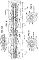
- FIG. 5 shows the whole three-piece rotor 90 including the rotor body 63 located between its drive and driven journals 91 and 92.
- the second rotor body 64 is the central section of a second three-piece rotor assembly 94 comprising a second drive journal 95, a second driven journal 96, with the second rotor body 64 being positioned between its drive and driven journals 95, 96 and having its rotational axis 65 (FIG. 4) aligned with corresponding rotational axes of the drive and driven journals 95, 96.
- the first and second drive journals 91 and 95 are rotationally supported in spaced parallel relationship in the drive end frame 38 by axially spaced spherical roller bearings 97, 98 having a bearing spacer sleeve 99 between them.
- the outer race of bearing 98 is held in an axially fixed position in the end frame 38 by an annular spacer 100 seated against an annular shoulder in the end frame 38 and by an extension 101 on a seal housing 102. Consequently, the two bearings 97, 98 are held axially fixed in their respective positions in the end frame 38.
- the top portion 105 of the end frame 38 can be removed from the bottom portion 106 along a split line (not shown) horizontally aligned with the axis 65 by removal of machine screws 107.
- each of these drive journals is keyed, as shown in FIG. 3B at 108, to a respective one of the two output shafts of transmission 36.
- the first and second drive journals 91 and 95 are disengageably coupled to the first and second rotor bodies 63 and 64, respectively, as will be explained in detail later by torque-transmitting coupling means including a loosenable locking collar 110 having spanner wrench ports (not shown) and set screws 111.
- the rotor body 63 is encircled by a visco seal assembly including an outer sleeve 112 and an inner sleeve 113 having a helically convoluted outer surface.
- a visco seal assembly including an outer sleeve 112 and an inner sleeve 113 having a helically convoluted outer surface.
- a hose clamp 109 encircles a projecting lip on the visco seal outer sleeve 112.
- the first and second driven journals 92, 96 are rotationally supported in spaced parallel relationship in the driven end frame 38 by axially spaced spherical roller bearings 114 and 115 separated by a bearing spacer sleeve 116. It is noted that the outer race of each of the bearings 114 and 115 for each of the driven journals 92 and 96 (FIG. 5) is free to shift in an axial direction within the driven end frame 39 for accommodating thermal expansion and contraction of both three-piece rotor assemblies 90 and 94 (FIG. 5). There are seal housings 104 (FIG. 3A) for the bearings 114 and 115.
- a lock nut 118 holds seal ring 120, bearings 115 and 114 with their spacer 116 and seal ring 124 which abuts against an enlarged journal head 142 on each driven journal 92 and 96 (FIG. 5).
- a top portion 121 of the driven end frame 39 can be removed from the bottom portion 122 along a split line (not shown) horizontally aligned with the axis 65 by removal of machine screws 107.
- seal ring 124 (FIG. 3A) near the bearing 114 and a similar seal ring 124 (FIG. 3B) near the bearing 97.
- a seal ring 125 (FIG. 3B) near the bearing 98 includes a notch 126 for providing clearance for a key (not shown) fitting in the keyway 108.
- packing 128 (FIG. 3B), for example graphite-impregnated braided packing, associated with a packing seal wear sleeve 129 and being compacted by a packing gland 130 fastened by machine screws (not shown) to a packing gland retainer 132 held by a clamp 134. Alignment of retainer 132 is assured by a dowel pin 133 as it is inserted through a locating hole in clamp 134.
- the first and second rotor bodies 63, 64 are conveniently uncoupled respectively from their first and second drive journals 91, 95 and from their first and second driven journals 92, 96.
- four shaft connections are uncoupled, thereby separating each of the rotors 90 and 94 (FIG. 5) into its three separate components.
- both of the uncoupled rotor body sections 63 and 64 can be lifted out, thereby providing convenient, unimpeded access to the entire inner surfaces 135 of the two cavities 61, 62 in lower liner 69.
- the removed rotor bodies 63 and 64 easily can be handled and moved to a nearby cleaning or maintenance area in the plant.
- the bearing assemblies in the drive and driven end frames 38 and 39 advantageously can remain fully assembled, i.e. can remain essentially undisturbed, when the rotor body sections 63 and 64 are uncoupled from their respective journals and lifted out of the mixer chamber barrel 40.
- novel quick-disconnect couplings 140 and 141 are incorporated in the two-rotor continuous mixer 22.
- FIG. 5 only one drive-end coupling 140 and only one driven-end coupling 141 are shown for clarity of illustration. It will be understood that actually there are two of each such coupling.
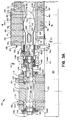
- FIG. 3B Shown in FIG. 3B is one of the two drive-end, quick-disconnect couplings 140.
- the threaded locking collar 110 is held captive on the drive journal 91 by an inner flange 145 overlapping behind an enlarged head or flange 142 on the drive journal 91.
- This enlarged head 142 has a concentric circular piloting rim or lip 143 projecting in the downstream direction forming a cup-like socket interface on the drive journal head 142.
- a circular cylindrical rotor pilot 144 is shown bolted onto the upstream end of the rotor body 63 by four machine screws 146 (only three are seen) inserted through bolt holes 147 (FIG. 5) in the pilot 144.
- This pilot 144 has an upstream concentric annular piloting surface shown snugly fitting plug-like into the piloting lip 143 forming the socket interface on the drive journal head 142.
- the pilot 144 also has a diametrically-extending key 150 projecting in the upstream direction engageable into a mating diametrically-extending keyway 148 in the downstream surface of drive journal head 142.
- the pilot 144 In addition to its upstream key 150, the pilot 144 also has a downstream diametrically-extending key 152 (FIG. 5) shown engaged into a mating diametrically-extending keyway 154 in the upstream end surface of the rotor body 63.
- the upstream end surface of the rotor body 63 has a concentric circular piloting rim or lip 156 projecting in the upstream direction.
- the pilot 144 has a downstream concentric annular piloting surface 158 (FIG. 5) snugly fitting plug-like within the piloting lip 156, as seen in FIG. 3B.
- the locking collar 110 is internally screw threaded at 160 (FIG. 5) for engagement with external screw threads 162 (FIG. 5) on the pilot 144.
- the joint interface between the pilot 144 and the downstream surface of the journal head 142 is compressively pre-loaded by tightening the locking collar 110 using a spanner wrench.
- the quick-disconnect coupling 141 (FIG. 3A) located near the downstream end of the mixer barrel 40. It is seen that the locking collar 117 has an inner flange 145 overlapping behind an enlarged head or flange 142 on driven journal 92, thereby keeping this collar captive on the driven journal.
- the enlarged head 142 has a concentric circular piloting rim or lip 143 projecting in the upstream direction forming a cup-like socket interface on journal 92.
- a circular cylindrical rotor pilot 164 (FIG. 3A) is bolted onto the downstream end of the rotor body 63 by four machine screws 146 (only one is seen) inserted through bolt holes 147 (FIG. 5) in the pilot 164.
- a thermal insulation ring 166 Interposed between the pilot 164 and the downstream end of the rotor body 63 is a thermal insulation ring 166 for reasons explained later.
- Four bolt holes 147 in this insulating ring are aligned with bolt holes 147 (FIG. 5) in the pilot 164.
- two torque-transmitting drive pins 168 project from the downstream end of the rotor body 63 through suitable holes in the insulation ring 166 and engage in sockets 170 (only one is seen) in the pilot 164. Less torque load at the driven end (compared with the drive end) allows use of drive pins 168 as keying means for the pilot 164.
- the pilot 164 has a downstream concentric annular piloting surface 165 (FIG. 5) shown snugly fitting plug-like within the piloting lip 143 forming the socket interface on the driven journal head 142.
- the pilot 164 also has a diametrically-extending key 172 projecting in a downstream direction engageable onto a mating diametrically-extending keyway 174 in the enlarged head 142 of the driven journal 92. It is noted that there is an axial bore through the pilot 164 for reasons to be explained later on, and thus the key 172 is seen in FIG. 5 comprising two radial portions.
- the driven journals 92 and 96 are shifted downstream for providing end-play clearance by sliding the free-floating outer races of bearings 114, 115 (FIG. 3A) downstream within the driven end frame 39. There is about one-half inch of free-floating clearance from an annular shoulder 175 within end frame 39, as indicated by the double-headed arrow 176 (FIG. 3A).
- Such downstream shifting by about one-half inch of the driven journals 92 and 96 withdraws lip 143 of driven journal head 142 from its encircling relationship around annular piloting surface 165 (FIG. 5) of pilot 164 and also allows the rotor bodies 63, 64 to be shifted downstream about one-quarter inch.
- This rotor zone cooling method and apparatus enables predetermined zones of the two rotors in a two-rotor continuous mixer to be cooled as may be desired and enables other predetermined zones to remain "neutral", i.e. without significant cooling.
- the present embodiment of the invention is shown installed and employed in three-piece rotors, it is to be understood that this invention also can be installed and employed to advantage in one-piece rotors in two-rotor continuous mixer machines.
- FIG. 3A An unusually long axial bore 180 (FIG. 3A) is fabricated in each of the rotors 90 and 94 (FIG. 5).
- This bore 180 extends from the downstream end (also called the "water end") of the rotor all of the way to a terminal end 182 (FIG. 3B) of the bore.
- This terminal end 182 is shown positioned within the portion of the rotor which is encircled by packing 128.
- this terminal end 182 of the bore 180 is shown in FIG. 3B to be located upstream beyond the upstream end of the mixer barrel 40 and its liners 68, 69.
- This terminal end 182 of the bore 180 is shown axially spaced less than about one inch from the downstream ends of pilot-mounting machine screws 146.
- the entrance 184 to the bore 180 is shown in FIG. 3A at the downstream end of the rotor, and this entrance 184 is also seen at the downstream end of each rotor 90 and 94 in FIG. 5.
- liquid coolant usually water
- coolant feed tube 186 In order to feed liquid coolant, usually water, into the unusually long bore 180 of the rotor, there is an elongated coolant feed tube 186 (FIG. 8) which is shown extending to within less than one inch of the bore terminus 182. Liquid coolant flows, as shown by arrows 188, through the passage 189 defined by this tube 186.
- This feed tube 186 and all of the other components seen in FIG. 8 rotate with the rotor, as will be explained in detail later, and so there is no relative motion between any of the components seen in FIG. 8. The coolant does flow relative to these various components, as will be explained.
- the coolant 188 exits, as shown by flow arrows 190, from the discharge end 187 of the feed tube 186 and bathes bore terminus 182 and the wall surface of rotor bore 180 for providing an effective cooling flow 191 within the rotor in a first cooling zone 192.
- first isolation tube section 195 For creating a first neutral zone 194, the flow of coolant 191 which was travelling exposed to the wall of rotor bore 180 is now channeled into the interior of a first isolation tube section 195.
- This isolation tube section 195 is supported in concentric relationship with the feed tube 186 by being welded to a pair of support rings 196 and 197 each of whose perimeters rests against the wall of rotor bore 180.
- a spider support ring 198 (FIG. 9) whose perimeter rests against the wall of rotor bore 180.
- This spider ring 198 has a plurality (four are shown) of inwardly extending radial legs 200 (FIG. 9) welded to feed tube 186.
- the spider 198 is spaced from the nearest isolation tube support ring 196 by a rabbeted ring fitting 204 having a circumferential shoulder 205 (FIG. 8A) overlapping an axially projecting lip 201 on the spider 198.
- the ring fitting 204 generally has a broad T-shape as seen in cross-section in FIG. 8A, with a second circumferential shoulder 205 overlapping an adjacent axially projecting lip 208 on the support ring 196.
- a seal 206 for example an O-ring or a lip seal
- adjacent portions of the spider 198 and fitting 204 are chamfered, as seen more clearly in FIG. 8A.
- adjacent portions of the fitting 204 and support ring 196 are chamfered.
- This pair of seals 206 engaging the wall of rotor bore 180 causes coolant flow to divert away from the bore wall and to go through spider passages 202 (FIG. 9) as shown by arrows 203 (FIG. 8). After the flow 203 has gone through spider passages 202, it is confined within an isolation channel 199 inside tube section 195. This isolation tube section 195 is spaced inwardly from the rotor bore wall; thus essentially no rotor cooling occurs within first neutral zone 194.
- the cooling/neutral/cooling/neutral, etc. tubing assembly technique uses a T-shaped fitting 204 with circumferential shoulders 205 overlapping lips on adjacent support rings. This advantageous technique is employed repeatedly along the length of the rotor bore 180.
- the support ring 197 has a configuration which is a mirror image of the other support ring 196 for isolation tubing section 195.
- the support ring 197 is assembled with its lip underlapping a shoulder on a second T-shaped ring fitting 204 which in turn has its other shoulder overlapping a lip on an adjacent tubing support ring 196.
- Another concentric tubing section 207 is supported by the second support ring 196 and is spaced inwardly from the wall of rotor bore 180.
- this tubing section 207 acts as a cooling augmentation (cooling booster) element by forcing a coolant flow 210 closely adjacent to the wall of rotor bore 180.
- this tube section 207 acts as a cooling augmentation (cooling booster) element by forcing a coolant flow 210 closely adjacent to the wall of rotor bore 180.
- cooling augmentation cooling booster
- there are a plurality of ports 216 (four ports are shown in FIG. 10) in the cooling augmentation tube section 207.
- the augmentation tube section 207 includes another plurality of radial ports 220 for allowing inward flow (arrows 222) into another cooling isolation channel 199 within another isolation tube section 195.
- An assembly of a T-shaped fitting 204 and adjacent tubing support rings 197 and 196 with a pair of bore-wall-engaging seals 206 causes the coolant to be diverted inwardly (arrows 222) from cooling augmentation channel 212 into cooling isolation channel 199.
- a second neutral zone 226 is provided.
- a sequence of alternating cooling/neutral/cooling/neutral/cooling/neutral zones can be provided including zones of various possible lengths and with various possible numbers of alternating zones.
- the user is provided with versatility in arranging patterns of the cooling and neutral zones, their relative locations along the bore of each rotor, their relative lengths and number of such zones, thereby having the opportunity to tailor or customize these zones to various compositions of plastic materials with various mixing temperature requirements in various regions along the length of a mixing chamber 60 (FIGS. 3A, 3B).
- a region near helical screw flight 72 pumping and feeding actions of plastic materials are occurring; then a significant amount of dispersive mixing often is occurring in a region of higher pressure downstream from the feedscrew 72 along upstream portions of mixing wings 73 upstream from cusps 74; and then a significant amount of distributive mixing often is occurring along downstream portions of mixing wings 73 downstream from cusps 74.
- the cooling and neutral zones advantageously can be patterned for optimizing the processing of plastic materials desired to take place in the various regions along the lengths of the rotors.
- This rotary joint mechanism 232 includes a rotatable coupling 234 with a screw-threaded connection into a tubular member 236 which has a shoulder 238 shown abutting against a driven journal 92 or 96 at the entrance 184 (FIG.3A) into the bore 180 of the driven journal.
- This axial bore 180 in the driven journal communicates as seen in FIG. 3A with an axial bore hole in the pilot 164, which in turn communicates with an axial bore hole in the insulator ring 166, which in turn communicates with the rotor bore 180.
- annular channel 244 in tubular member 236 and enters the coupling 234 which is rotatable in conformity with rotation 58 (FIG. 4) of the respective rotor assemblies 90, 94 (FIG. 5).
- the returning coolant flow in annular channel 244 passes through the rotary joint mechanism 232 and issues through an outlet 246 as shown by an arrow 248.
- a stop 250 has clearances at 252 for permitting returning coolant flow to by-pass this stop 250 in entering the coupling 234.
- a compression spring 254 is associated with the rotary joint mechanism 232.
- another compression spring 256 seats against bore terminus 182 and presses against the spider ring 198 for compressively loading to hold in closely adjacent overlapping relationships all of the respective rabbeted joint assemblies involving the various ring fittings 204.
- a novel system and method provides greased end frame bearing assemblies.
- novel thermal isolation and novel localized cooling high temperature grease is enabled to be used successfully in the journal bearing assemblies of two-rotor mixers for plastic materials embodying the present invention.
- the seal housings 104 at opposite ends of the driven-journal end frame 39 are equipped with lubrication grease fittings 260 for greasing bearings 114 and 115.
- the seal housings 102 and 104 at opposite ends of the drive-journal end frame 38 are equipped with lubrication grease fittings 260 for greasing the bearings 98 and 97.
- the four bearings 98 and 97 (only two are seen in FIG. 3B) for the drive journals 91 and 95 (FIG. 5) are spherical-type roller bearings and also the four bearings 114 and 115 (only two are seen in FIG. 3A) for the driven journals 92, 96 are spherical-type roller bearings.
- a suitable high-temperature grease is injected into the bearings through the grease fittings 260.
- a suitable high-temperature grease which has been found to operate successfully in the present embodiment of the invention is commercially available from Davis-Howland Oil Corporation of Rochester, New York under the mark "LUBRIPLATE 630-2".
- a suitable thermal insulation ring 166 of relatively high compressive strength is interposed between the downstream end of each rotor body and the pilot 164.
- a suitable heat insulation material having sufficient compressive strength for fabricating this thermal insulation ring 166 is asbestos-free "ZIRCAR" fibrous ceramic refractory, Type 100, commercially available from Zircar Products, Inc. of Florida, New York.
- This refractory insulation has a thermal conductivity in the range from about 4.40 to about 4.42 Btu per hour, degree F, square foot per inch of thickness. This thermal conductivity range occurs over a temperature range from about 390°F to about 1,100°F.
- the four machine screws 146 and the two drive pins 168 extending through this ring are of stainless steel composition which offers considerably less thermal conductivity than customary steel screws and pins of the same size and shape.
- the rotor zone cooling described above is arranged for providing augmented cooling for at least a major portion of the length of the bore 180 of each driven journal 92, 96 to serve as a heat sink therein.
- the rotor bore 180 is unusually long, as described above, with its terminus 182 being shown located farther upstream than the upstream end of the mixer barrel 40 and its liners 68, 69. In other words, this terminus 182 actually is shown located closer to the end frame 38 than the mixer barrel 40 and its liners 68, 69.
- the fresh coolant 188 (FIG. 8) issuing from the discharge end 187 of the feed tube 186 and striking the terminus 182 as shown by flow arrows 190.
- This effective cooling action by fresh coolant flow 188, 190 at a location very near to the upstream end of the rotor body serves as a heat sink for cooling the drive journals 91 and 95 (FIG. 5) and thus thermally isolates the drive-journal end frame 38 from the mixer barrel 40.
- each of the end frames 38, 39 is spaced relatively far from the mixer barrel 40 enabling some cooling action to occur by ambient air in the region between mixer barrel and respective end frames.
Landscapes
- Engineering & Computer Science (AREA)
- Mechanical Engineering (AREA)
- General Engineering & Computer Science (AREA)
- Processing And Handling Of Plastics And Other Materials For Molding In General (AREA)
- Mixers Of The Rotary Stirring Type (AREA)
- Containers And Packaging Bodies Having A Special Means To Remove Contents (AREA)
- Quick-Acting Or Multi-Walled Pipe Joints (AREA)
Claims (16)
- Schnellauskuppelbare Kupplungseinrichtungen (140, 141) zur Verwendung in einem dreiteiligen Rotor (90, 94) für einen kontinuierlichen Mischer (22) von plastischen Materialien (24), wobei der dreiteilige Rotor (90, 94) zwei Wellenzapfen (91, 92, 95, 96) mit jeweils einer Drehachse (65) und einen Hauptrotorkörper (63, 64) mit einer Drehachse (65) aufweist und für eine Installation zwischen den beiden Wellenzapfen (91, 92, 95, 96) geeignet ist, wobei die schnellauskuppelbaren Kupplungseinrichtungen (140, 141) aufweisen:erste Berührungsflächenabgrenzungseinrichtungen (144, 164), die an einem Ende des Hauptrotorkörpers (63, 64) starr befestigt sind;zweite Berührungsflächenabgrenzungseinrichtungen (142), die an einem Ende des Wellenzapfens (91, 92, 95, 96) starr befestigt sind; dadurch gekennzeichnet, daß:die ersten Berührungsflächenabgrenzungseinrichtungen (144, 164) erste Konzentrizitätsführungseinrichtungen (165) aufweisen, die mit der Drehachse (65) des Hauptrotorkörpers (63, 64) konzentrisch sind;die zweiten Berührungsflächenabgrenzungseinrichtungen (142) zweite Konzentrizitatsführungseinrichtungen (143) aufweisen, die mit der Drehachse (65) des Wellenzapfens (91, 92, 95, 96) konzentrisch ist;wobei die ersten und zweiten Konzentrizitätsführungseinrichtungen (165, 143) losbar eingriffsfähig sind zum Ausrichten der Achse (65) des Hauptrotorkörpers (63, 64) mit der Achse (65) des Wellenzapfens (91, 92, 95, 96) bei Eingriff der ersten und zweiten Konzentrizitätsführungseinrichtungen (165, 143);wobei die ersten Berührungsflächenabgrenzungseinrichtung (144, 164) erste Verkeilungseinrichtungen (150, 152, 172) aufweisen;die zweiten Berührungsflächenabgrenzungseinrichtungen (142) zweite Verkeilungseinrichtungen (148, 154, 174) aufweisen;die ersten und zweiten Verkeilungseinrichtungen (150, 152, 172, 148, 154, 174) lösbar eingriffsfähig sind zur Drehmomentenübertragung zwischen dem Hauptrotorkörper (63, 64) und dem Wellenzapfen (91, 92, 95, 96);lösbaren Verriegelungseinrichtungen (110, 117) zum lösbaren Verriegeln der ersten und zweiten Berührungsflächenabgrenzungseinrichtungen (144, 164, 142) miteinander, wobei die ersten und zweiten Konzentrizitätsführungseinrichtungen (165, 143) lösbar miteinander in Eingriff treten zum Ausrichten der Achsen (65) und wobei die ersten und zweiten Verkeilungseinrichtungen (150, 152, 172, 148, 154, 174) lösbar miteinander in Eingriff treten zur Drehmomentenübertragung;wobei die ersten Konzentrizitätsführungseinrichtungen (165) eine erste kreisförmige zylindrische Fläche auf den ersten Berührungsflächenabgrenzungseinrichtungen (144, 164) sind, die mit der Drehachse (65) des Hauptrotorkörpers (63, 64) konzentrisch ist;die zweiten Konzentrizitätsführungseinrichtungen (143) eine zweite kreisförmige zylindrische Fläche auf den zweiten Berührungsflächenabgrenzungseinrichtungen (142) sind, die mit der Drehachse (65) des Wellenzapfens (91, 92, 95, 96) konzentrisch ist;eine der kreisförmigen zylindrischen Flächen eine kreisförmige zylindrische Außenfläche ist;die andere der kreisförmigen zylindrischen Flächen eine kreisförmige zylindrische Innenfläche ist;wobei die kreisförmige zylindrische Außenfläche geeignet ist, durch axiales zapfenartiges Einfügen genau in die kreisförmige zylindrische Innenfläche zu passen, zur Ausrichtung der Drehachsen des Hauptrotorkörpers (63, 64) und des Wellenzapfens (91, 92, 95, 96);die ersten Verkeilungseinrichtungen (150, 152, 172) sich senkrecht zur Drehachse (65) des Hauptrotorkörpers (63, 64) erstrecken;die zweiten Verkeilungseinrichtungen (148, 154, 174) sich senkrecht zur Drehachse (65) des Wellenzapfens (91, 92, 95, 96) erstrecken;eine der ersten und zweiten Verkeilungseinrichtungen (150, 152, 172) ein Keil mit beabstandeten parallelen Wänden ist; unddie andere der ersten und zweiten Verkeilungseinrichtungen (148, 154, 174) eine Keilnut mit beabstandeten parallelen Wänden ist, die geeignet ist, den Keil genau in die Keilbahn aufzunehmen.
- Schnellauskuppelbare Kupplungseinrichtung (140, 141) nach Anspruch 1, wobei:der Keil (150, 152, 172) und die kreisförmige zylindrische Außenfläche (165) beide an den gleichen Berührungsflächenabgrenzungseinrichtungen (144, 164) sind.
- Schnellauskuppelbare Kupplungseinrichtungen (140, 141) nach Anspruch 1, wobei:der Keil (150, 152, 172) und die zylindrische Außenfläche (165) beide an den ersten Berührungsflächenabgrenzungseinrichtungen (144, 164) sind.
- Schnellauskuppelbare Kupplungseinrichtungen (140, 141) nach Anspruch 1, wobei:die kreisförmige zylindrische Innenfläche (143) die Innenfläche eines Randes ist, der eine becherartige Fassung an einer der Berührungsflächenabgrenzungseinrichtungen (142) umgibt;die kreisförmige zylindrische Außenfläche (165) einen zapfenartigen Vorsprung an der anderen der Berührungsflächenabgrenzungseinrichtungen (144, 164) umgibt, der geeignet ist, genau in die becherartige Fassung zu passen;die Keilnut (148, 154, 174) sich diametral über die becherartige Fassung erstreckt und sich an zwei diametral entgegengesetzten Stellen durch den Rand (143) erstreckt; undder Keil (150, 152, 172) sich diametral über ein axiales Ende des zapfenartigen Vorsprungs erstreckt.
- Schnellauskuppelbare Kupplungseinrichtungen (140, 141) zur Verwendung mit einem dreiteiligen Rotor (90, 94) für einen kontinuierlichen Mischer (22) von plastischen Materialien (24), wobei ein solcher dreiteiliger Rotor (90, 94) drei Komponenten aufweist, die zwei Wellenzapfen (91, 92, 95, 96) mit jeweils einer Drehachse (65) und einen Hauptrotorkörper (63, 64) mit einer Drehachse (65) aufweisen, und wobei der Hauptrotorkörper (63, 64) zwischen den beiden Wellenzapfen (91, 92, 95, 96) positioniert ist, wobei die schnellauskuppelbaren Kupplungseinrichtungen (140, 141) aufweisen:ein zapfenartiges Führungsteil (144, 164), das an einem Ende einer der Komponenten fest angeordnet ist;wobei das Führungsteil (144, 164) eine kreisförmige zylindrische Außenfläche (165, 158) hat, die mit der Drehachse (65) der einen Komponente konzentrisch ist; dadurch gekennzeichnet, daß:das zapfenartige Führungsteil (144, 164) einen Keil (150, 152, 172) hat, der sich diametral über ein axiales Ende des Führungsteils erstreckt;eine andere der Komponenten eine becherartige Fassung (143) hat, wobei ein Rand die becherartige Fassung umgibt;wobei der Rand (143) eine kreisförmige zylindrische Innenfläche (143, 156) hat, die mit der Drehachse (65) der anderen Komponente konzentrisch ist;die andere Komponente einen Keil (148, 154, 174) hat, der sich diametral über die becherartigen Fassungen erstreckt;die becherartige Fassung (143) eine zapfenartige Führungseinrichtung (165, 158) lösbar in sich aufnimmt, zum Ausrichten der Drehachsen (65) der einen und der anderen Komponente;die Keilnut (148, 154, 174) den Keil (150, 152, 172) lösbar genau in sich aufnimmt, zur Drehmomentübertragung zwischen der einen und der anderen Komponente; undeine lösbare Verriegelungseinrichtung zum lösbaren Halten des zapfenartigen Führungsteils (144, 164) in der becherartigen Fassung (143) und auch zum lösbaren Halten des Keils (150, 152, 172) in der Keilnut (148, 154, 174).
- Schnellauskuppelbare Kupplungseinrichtungen (140, 141) nach Anspruch 5, wobei:die eine Komponente, an deren einem Ende das zapfenartige Führungsteil (144, 164) fest angeordnet ist, der Hauptrotorkörper (63, 64) ist.
- Schnellauskuppelbare Kupplungseinrichtungen (140, 141) nach Anspruch 6, wobei:das zapfenartige Führungsteil (144) an ein Ende des Hauptrotorkörpers (63, 64) geschraubt ist;das Führungsteil (144) mit dem Ende des Hauptrotorkörpers (63, 64) zur Drehmomentenübertragung verkeilt ist (152); undKonzentrizitätseinrichtungen (156) an dem Ende des Hauptrotorkörpers (63, 64) und an dem zapfenartigen Führungsteil (144) miteinander in einem zapfenartigen genauen Sitz in Eingriff stehen, zum Halten des zapfenartigen Führungsteils (144) in konzentrischer Ausrichtung mit der Drehachse (65) des Hauptrotorkörpers (63, 64).
- Schnellauskuppelbare Kupplungseinrichtungen (140, 141) nach Anspruch 7, wobei:das zapfenartige Führungsteil (144, 164) eine Außengewindefläche (162) hat, die mit seiner Drehachse (65) konzentrisch ist;die lösbaren Verriegelungseinrichtungen eine Innengewindemuffe (110, 117) aufweisen;die Muffe (110, 117) auf dem Wellenzapfen (91, 92, 95, 96) festgehalten wird;die Muffe (110, 117) lösbar schraubgewindeeingriffsfähig mit der Außenschraubgewindefläche (162) des zapfenartigen Führungsteils (144, 164) ist, zum Vorbelasten des Führungsteils (144, 164) gegen den Wellenzapfen (91, 92, 95, 96); unddie Muffe (110, 117) eine geeignete Einrichtung zum Halten der Muffe in Schraubgewindeeingriff mit der Außenschraubgewindefläche (162) des zapfenartigen Führungsteils (144, 164) aufweist.
- Schnellauskuppelbare Kupplungseinrichtungen (140, 141) zur Verwendung in einem dreiteiligen Rotor (90, 94) für einen kontinuierlichen Mischer (22) von plastischen Materialien (24), wobei der dreiteilige Rotor (90, 94) einen Hauptrotorkörper (63, 64) und einen ersten und einen zweiten Wellenzapfen (91, 92, 95, 96) aufweist und der Hauptrotorkörper (63, 64) eine Drehachse (65) hat und zwischen dem ersten und dem zweiten Wellenzapfen (91, 92, 95, 96) installiert ist, wobei seine Drehachse (65) mit einer Drehachse (65) jedes Wellenzapfens ausgerichtet ist, wobei die schnellauskuppelbaren Kupplungseinrichtungen (140, 141) aufweisen:ein erstes und zweites Führungsteil (144, 164) mit jeweils einer Drehachse (65); dadurch gekennzeichnet, daß:das erste und zweite Führungsteil (144, 164) geeignet ist zur Befestigung an entgegengesetzten Enden des Hauptrotorkörpers (63, 64), wobei deren jeweilige Drehachsen (65) mit der Drehachse (65) des Rotorkörpers (63, 64) in mit dieser konzentrischer verkeilter Beziehung ausgerichtet sind, zur Drehmomentenübertragung zwischen dem Hauptrotorkörper (63, 64) und dem jeweiligen Führungsteil (144, 164);das erste und zweite Führungsteil (144, 164) erste bzw. zweite Verkeilungseinrichtungen (150, 152, 172) aufweisen zum lösbaren festsitzenden Keileingriff mit zusammenpassenden ersten bzw. zweiten Verkeilungseinrichtungen (148, 154, 174) am ersten bzw. zweiten Wellenzapfen (91, 92, 95, 96) zur Drehmomentübertragung zwischen dem ersten bzw. zweiten Führungsteil (144, 164) und dem ersten bzw. dem zweiten Wellenzapfen (91, 92, 95, 96);wobei das erste und zweite Führungsteil (144, 164) jeweils eine kreisförmige zylindrische Fläche (165) haben, die mit ihren jeweiligen Drehachsen (65) konzentrisch ist;der erste und zweite Wellenzapfen (91, 92, 95, 96) jeweils eine kreisförmige zylindrische Fläche (143) haben, die mit ihren Drehachsen (65) konzentrisch ist;die kreisförmige zylindrische Fläche (165) an dem ersten und zweiten Führungsteil (144, 164) lösbar genau eingriffsfähig mit der jeweiligen kreisförmigen zylindrischen Fläche (143) an dem ersten und zweiten Wellenzapfen (91, 92, 95, 96) ist, zum Ausrichten der Drehachse (65) des ersten und zweiten Führungsteils (144, 164) mit der Drehachse (65) des ersten bzw. zweiten Wellenzapfens (91, 92, 95, 96);das erste und zweite Führungsteil (144, 164) Gewindeflächen (162) haben;die erste und zweite Verriegelungsmuffe (110, 117) auf dem ersten und zweiten Wellenzapfen (91, 92, 95, 96) festgehalten werden;die erste und zweite Verriegelungsmuffe (110, 117) Gewindeflächen (160) haben, die lösbar eingriffsfähig mit Gewindeflächen (162) am ersten bzw. zweiten Führungsteil (144, 164) sind, zum Vorbelasten des ersten und des zweiten Führungsteils (144, 164) gegen den ersten bzw. zweiten Wellenzapfen (91, 92, 95, 96); undlösbare Sicherungseinrichtungen zum Halten der Gewindefläche der ersten und zweiten Muffe (110, 117) in Eingriff mit den Gewindeflächen des ersten bzw. zweiten Führungsteils (144, 164).
- Schnellauskuppelbare Kupplungseinrichtungen (140, 141) nach Anspruch 9, wobei:der erste und zweite Wellenzapfen (91, 92, 95, 96) eine erste bzw. zweite becherförmige Berührungsfläche (143) haben;die erste und zweite becherförmige Berührungsfläche (143) einen ersten bzw. einen zweiten Rand (143) haben;die kreisförmige zylindrische Fläche (143) am ersten und zweiten Wellenzapfen (91, 92, 95, 96) Innenflächen des ersten bzw. zweiten Randes (143) sind;die ersten und zweiten Verkeilungseinrichtungen an dem ersten bzw. zweiten Wellenzapfen eine erste bzw. zweite Keilnut (148, 154, 174) sind, die sich diametral über die erste und zweite becherförmige Berührungsfläche (143) erstrecken;die ersten und zweiten Verkeilungseinrichtungen an dem ersten bzw. zweiten Führungsteil ein erster bzw. zweiter Keil (150, 152, 172) sind, die sich diametral über axiale Enden des ersten bzw. zweiten Führungsteils (144, 164) erstrecken;die erste und zweite zylindrische Fläche (165) an dem ersten bzw. zweiten Führungsteil (144, 164) kreisförmige zylindrische Außenflächen (165) sind, die genau passend lösbar einfügbar in den ersten bzw. zweiten Rand (143) sind; unddie erste und zweite Verriegelungsmuffe (110, 117) das erste bzw. zweite Führungsteill (144, 164) gegen die erste bzw. zweite becherförmige Berührungsfläche (143) vorbelasten und außerdem den ersten und zweiten Keil (150, 152, 172) in der ersten bzw. zweiten Keilnut (148, 154, 174) halten.
- Schnellauskuppelbare Kupplungseinrichtungen (140, 141) nach Anspruch 10, wobei:der erste und zweite Wellenzapfen (91, 92, 95, 96) einen ersten bzw. Zweiten vergrößerten Kopf (142) haben;die erste und zweite becherförmige Berührungsfläche (143) an dem ersten bzw. dem zweiten vergrößerten Kopf (142) sind; unddie erste und zweite Verriegelungsmuffe (110, 117) Innenflansche (145, 160) haben, die hinter den vergrößerten Köpfen festgehalten werden, zum Festhalten der Verriegelungsmuffen (110, 117) auf dem ersten bzw. zweiten Wellenzapfen (91, 92, 95, 96).
- Schnellauskuppelbare Kupplungseinrichtungen (140, 141) nach Anspruch 11, wobei:die ersten und zweiten Keilnuten (148, 174) sich diametral über die ersten und zweiten Ränder (143) erstreckt; unddie lösbaren Sicherungseinrichtungen zum Halten der Gewindeflächen (160) der ersten und zweiten Muffen (110, 117) in Eingriff mit den Gewindeflächen (162) der ersten bzw. zweiten Führungsteile (144, 164) Stellschrauben in den ersten und zweiten Verriegelungsmuffen (110, 117) sind.
- Schnellauskuppelbare Kupplungseinrichtungen nach einem der Ansprüche 1 bis 12, wobei:eine der ersten und zweiten Führungseinrichtungen (144, 164) einen zapfenartigen Vorsprung (165, 158) mit der kreisförmigen zylindrischen Außenfläche aufweist;eine der ersten und zweiten Verkeilungseinrichtungen ein Keil (150, 152, 172) mit beabstandeten parallelen Wänden ist;der Keil (150, 152, 172) sich diametral über ein axiales Ende des zapfenartigen Vorsprungs (165, 158) erstreckt;die andere der ersten und zweiten Führungseinrichtungen ein Kopfteil mit einem axial vorspringenden Rand ist, der eine becherartige Fassung (143) umgibt;der Rand die kreisförmige zylindrische Innenfläche begrenzt;die andere der ersten und zweiten Keileinrichtungen eine Keilnut (148, 154, 174) mit beabstandeten parallelen Wänden ist;die Keilnut (148, 154, 174) sich diametral über die becherartige Fassung (143) erstreckt und sich an zwei diametral gegenüberliegenden Stellen durch den Rand erstreckt;der zapfenartige Vorsprung (165, 158) aufnahmefähig fest in die becherartige Fassung (153) ist; undder Keil (150, 152, 172) genau passend aufnahmefähig in die Keilnut (148, 154, 174) ist,
- Schnellauskuppelbare Kupplungseinrichtungen nach Anspruch 13, wobei:die lösbaren Verriegelungseinrichtungen eine Innengewindemuffe (110, 117) sind, die das Kopfteil umgibt;die Muffe einen einwärts gekehrten, hinter dem Hauptrotorkörper angeordneten Flansch (145, 160) hat, zum Festhalten des Flansches an dem Kopfteil;die Führungseinrichtungen (144, 164), die den zapfenartigen Vorsprung (165, 158) aufweisen, Außengewinde zum Schraubgewindeeingriff mit der Innengewindemuffe (110, 117) haben, zum Halten des Keils (150, 152, 172) in der Keilnut (148, 154, 174) und zum Halten des zapfenartigen Vorsprungs (165, 158) in der becherartigen Fassung (142); unddie Muffe (110, 117) eine lösbare Halteeinrichtung aufweist, um zu verhindern, daß sich die Muffe aus dem passenden Schraubgewindeeingriff löst.
- Schnellauskuppelbare Kupplungseinrichtungen nach Anspruch 14, wobei:die Führungseinrichtungen (144, 164), die die zapfenartige Verbindung (165, 158) aufweisen, an einem Ende des Hauptrotorkörpers (63, 64) befestigt sind;die Führungseinrichtungen (144, 164), die ein Kopfteil sind, an einem Ende eines Wellenzapfens (91, 92, 95, 96) sind; unddie Muffe (110, 117) nach dem Herausschrauben aus dem Schraubgewindeeingriff axial entlang dem Wellenzapfen (91, 92, 95, 96) weg von dem Kopfteil (165, 158) verschiebbar ist, damit das zapfenartige Teil aus der becherartigen Fassung (143) herausbewegt werden kann.
- Schnellauskuppelbare Kupplungseinrichtungen nach Anspruch 13, 14 oder 15, wobei:der zapfenartige Vorsprung (165, 158) eine axiale Bohrung hat, die sich konzentrisch mit der kreisförmigen zylindrischen Außenfläche durch diesen erstreckt;die axiale Bohrung sich durch den Keil (150, 152, 172) erstreckt und den Keil in zwei radiale Abschnitte teilt;das Kopfteil eine axiale Bohrung hat, die sich durch dieses erstreckt; unddie axiale Bohrung sich durch die Keilnut (148, 154, 174) erstreckt und die Keilnut in zwei radiale Abschnitte teilt.
Applications Claiming Priority (3)
| Application Number | Priority Date | Filing Date | Title |
|---|---|---|---|
| US07/711,941 US5259688A (en) | 1991-06-07 | 1991-06-07 | Quick-disconnect couplings for three-piece rotors in continuous mixers for plastic materials |
| US711941 | 1991-06-07 | ||
| PCT/US1992/004715 WO1992021497A2 (en) | 1991-06-07 | 1992-06-04 | Quick-disconnect couplings for three-piece rotors in continuous mixers for plastic materials |
Publications (2)
| Publication Number | Publication Date |
|---|---|
| EP0587785A1 EP0587785A1 (de) | 1994-03-23 |
| EP0587785B1 true EP0587785B1 (de) | 1999-05-19 |
Family
ID=24860132
Family Applications (1)
| Application Number | Title | Priority Date | Filing Date |
|---|---|---|---|
| EP92913804A Expired - Lifetime EP0587785B1 (de) | 1991-06-07 | 1992-06-04 | Schnell auskuppelbare Kupplung für dreiteilige Rotoren in kontinuierlichen Mischern für plastische Materialien |
Country Status (13)
| Country | Link |
|---|---|
| US (1) | US5259688A (de) |
| EP (1) | EP0587785B1 (de) |
| JP (1) | JPH06508079A (de) |
| KR (1) | KR100212431B1 (de) |
| CN (1) | CN1031331C (de) |
| AT (1) | ATE180200T1 (de) |
| AU (1) | AU659049B2 (de) |
| BR (1) | BR9206117A (de) |
| CA (1) | CA2110793C (de) |
| DE (1) | DE69229226T2 (de) |
| ES (1) | ES2131072T3 (de) |
| MX (1) | MX9202697A (de) |
| WO (1) | WO1992021497A2 (de) |
Families Citing this family (2)
| Publication number | Priority date | Publication date | Assignee | Title |
|---|---|---|---|---|
| US7476017B2 (en) * | 2005-09-29 | 2009-01-13 | Jacques Mortimer | Intermeshing kneader with tilting mixing chamber |
| CN102094974B (zh) * | 2011-01-13 | 2014-07-16 | 浙江双辉剑机械有限公司 | 一种沙滩车转向器的轴端密封装置 |
Family Cites Families (15)
| Publication number | Priority date | Publication date | Assignee | Title |
|---|---|---|---|---|
| US793690A (en) * | 1905-03-24 | 1905-07-04 | Kearney P Snyder | Coupling. |
| GB235554A (en) * | 1924-06-10 | 1926-02-18 | British Thomson Houston Co Ltd | Improvements in and relating to shaft couplings or the like |
| US2960851A (en) * | 1959-05-25 | 1960-11-22 | Peter L Ciaccio | Coupling for flexible drive cables for sewer cleaners and the like |
| GB1340219A (en) * | 1970-08-01 | 1973-12-12 | Scheer & Cie C F | Devices for plasticising and extruding plastics material |
| US4310251A (en) * | 1970-11-20 | 1982-01-12 | Intercole Automation, Inc. | Continuous mixer internal pressure control |
| CH614503A5 (en) * | 1977-01-27 | 1979-11-30 | Sulzer Ag | Rigid shaft coupling, in particular for turbo machines |
| DE3328397A1 (de) * | 1983-08-05 | 1985-02-21 | Heinz Dipl.-Ing. Weber | Kupplungsvorrichtung zur drehmomentuebertragenden verbindung zweier wellen |
| CH662621A5 (de) * | 1983-10-24 | 1987-10-15 | Bbc Brown Boveri & Cie | Wellenkupplung. |
| JPS60252822A (ja) * | 1984-05-25 | 1985-12-13 | Koyo Seiko Co Ltd | 軸又は類似の部材の連結装置 |
| DE3426159A1 (de) * | 1984-07-16 | 1986-01-23 | Herfeld, Friedrich Walter, Dr., 5982 Neuenrade | Mischvorrichtung |
| US4655630A (en) * | 1985-12-31 | 1987-04-07 | Dana Corporation | Robot arm end adapter |
| US5022645A (en) * | 1988-11-25 | 1991-06-11 | Eastman Kodak Company | Disengageable coupling usable in a sheet transport mechanism |
| CA2006824A1 (en) * | 1989-01-09 | 1990-07-09 | Theodore F. Gundlach | Shaft coupling |
| GB2236534B (en) * | 1989-09-29 | 1993-02-03 | Day Jiann Jinn | A tyre |
| US5061077A (en) * | 1989-12-14 | 1991-10-29 | Whiteman Marvin E Jr | Knock out paddle shaft for mixing machines |
-
1991
- 1991-06-07 US US07/711,941 patent/US5259688A/en not_active Expired - Fee Related
-
1992
- 1992-06-04 EP EP92913804A patent/EP0587785B1/de not_active Expired - Lifetime
- 1992-06-04 DE DE69229226T patent/DE69229226T2/de not_active Expired - Fee Related
- 1992-06-04 AU AU21897/92A patent/AU659049B2/en not_active Ceased
- 1992-06-04 KR KR1019930703774A patent/KR100212431B1/ko not_active Expired - Fee Related
- 1992-06-04 AT AT92913804T patent/ATE180200T1/de not_active IP Right Cessation
- 1992-06-04 ES ES92913804T patent/ES2131072T3/es not_active Expired - Lifetime
- 1992-06-04 CA CA002110793A patent/CA2110793C/en not_active Expired - Fee Related
- 1992-06-04 JP JP5500657A patent/JPH06508079A/ja active Pending
- 1992-06-04 WO PCT/US1992/004715 patent/WO1992021497A2/en not_active Ceased
- 1992-06-04 BR BR9206117A patent/BR9206117A/pt not_active IP Right Cessation
- 1992-06-05 MX MX9202697A patent/MX9202697A/es not_active IP Right Cessation
- 1992-06-06 CN CN92103878A patent/CN1031331C/zh not_active Expired - Fee Related
Also Published As
| Publication number | Publication date |
|---|---|
| WO1992021497A3 (en) | 1993-01-07 |
| ATE180200T1 (de) | 1999-06-15 |
| BR9206117A (pt) | 1995-03-07 |
| AU659049B2 (en) | 1995-05-04 |
| US5259688A (en) | 1993-11-09 |
| DE69229226T2 (de) | 1999-09-23 |
| EP0587785A1 (de) | 1994-03-23 |
| WO1992021497A2 (en) | 1992-12-10 |
| CA2110793A1 (en) | 1992-12-10 |
| CN1067605A (zh) | 1993-01-06 |
| KR940701325A (ko) | 1994-05-28 |
| ES2131072T3 (es) | 1999-07-16 |
| JPH06508079A (ja) | 1994-09-14 |
| CN1031331C (zh) | 1996-03-20 |
| AU2189792A (en) | 1993-01-08 |
| CA2110793C (en) | 1998-02-24 |
| KR100212431B1 (ko) | 1999-08-02 |
| DE69229226D1 (de) | 1999-06-24 |
| MX9202697A (es) | 1992-12-01 |
Similar Documents
| Publication | Publication Date | Title |
|---|---|---|
| US5180225A (en) | Rotor zone cooling apparatus for rotors in continuous mixers of plastic materials | |
| US5382089A (en) | Convenient access for clean-out and maintenance of mixing chamber and both rotors in two-rotor continuous mixers for plastic materials | |
| US5259671A (en) | Greased journal bearing assemblies with thermal isolation and cooling in continuous mixers of plastic materials | |
| CN102066769B (zh) | 涉及泵密封组件的改进 | |
| US5547277A (en) | Preheating screw | |
| US5273356A (en) | Rotor zone cooling method and apparatus for rotors in continuous mixers of plastic materials | |
| KR100193996B1 (ko) | 혼합 탄성 중합체용 계량 기어 펌프 | |
| US8113814B2 (en) | Barrel clamping system for quick assembling and dismantling of extruder barrel sections | |
| JPS63112139A (ja) | 混合兼押出装置 | |
| EP0688600A1 (de) | Kontinuierlicher Mischer und Apparat zum Entfernen von Rotorsegmenten für diesen Mischer | |
| CN210940383U (zh) | 同向平行双螺杆挤出机的结构 | |
| US6190031B1 (en) | Machine for continuous processing of flowable materials having a housing jacket divided into long and short segments | |
| US5259688A (en) | Quick-disconnect couplings for three-piece rotors in continuous mixers for plastic materials | |
| WO1995001517A1 (en) | Coupling rotor bodies to journals | |
| US9056292B2 (en) | Barrel alignment in extruder systems | |
| GB2125940A (en) | Heatable valve | |
| CN110561722B (zh) | 同向平行双螺杆挤出机的结构 | |
| US4887907A (en) | Rotary extruder with internally cooled rotor | |
| CN214926954U (zh) | 一种积木式单螺杆挤出机 | |
| CN105109015B (zh) | 一种螺杆支撑装置及具有该装置的双螺杆挤出机 | |
| JPS6195924A (ja) | バレルに軸受を設けた押出機 |
Legal Events
| Date | Code | Title | Description |
|---|---|---|---|
| PUAI | Public reference made under article 153(3) epc to a published international application that has entered the european phase |
Free format text: ORIGINAL CODE: 0009012 |
|
| AK | Designated contracting states |
Kind code of ref document: A1 Designated state(s): AT DE ES FR GB IT NL |
|
| 17P | Request for examination filed |
Effective date: 19940105 |
|
| 17Q | First examination report despatched |
Effective date: 19950203 |
|
| GRAG | Despatch of communication of intention to grant |
Free format text: ORIGINAL CODE: EPIDOS AGRA |
|
| GRAG | Despatch of communication of intention to grant |
Free format text: ORIGINAL CODE: EPIDOS AGRA |
|
| GRAH | Despatch of communication of intention to grant a patent |
Free format text: ORIGINAL CODE: EPIDOS IGRA |
|
| GRAH | Despatch of communication of intention to grant a patent |
Free format text: ORIGINAL CODE: EPIDOS IGRA |
|
| GRAA | (expected) grant |
Free format text: ORIGINAL CODE: 0009210 |
|
| AK | Designated contracting states |
Kind code of ref document: B1 Designated state(s): AT DE ES FR GB IT NL |
|
| REF | Corresponds to: |
Ref document number: 180200 Country of ref document: AT Date of ref document: 19990615 Kind code of ref document: T |
|
| ITF | It: translation for a ep patent filed | ||
| REF | Corresponds to: |
Ref document number: 69229226 Country of ref document: DE Date of ref document: 19990624 |
|
| REG | Reference to a national code |
Ref country code: ES Ref legal event code: FG2A Ref document number: 2131072 Country of ref document: ES Kind code of ref document: T3 |
|
| ET | Fr: translation filed | ||
| PLBE | No opposition filed within time limit |
Free format text: ORIGINAL CODE: 0009261 |
|
| STAA | Information on the status of an ep patent application or granted ep patent |
Free format text: STATUS: NO OPPOSITION FILED WITHIN TIME LIMIT |
|
| 26N | No opposition filed | ||
| PGFP | Annual fee paid to national office [announced via postgrant information from national office to epo] |
Ref country code: FR Payment date: 20000517 Year of fee payment: 9 |
|
| PGFP | Annual fee paid to national office [announced via postgrant information from national office to epo] |
Ref country code: DE Payment date: 20000518 Year of fee payment: 9 |
|
| PGFP | Annual fee paid to national office [announced via postgrant information from national office to epo] |
Ref country code: GB Payment date: 20000519 Year of fee payment: 9 Ref country code: AT Payment date: 20000519 Year of fee payment: 9 |
|
| PGFP | Annual fee paid to national office [announced via postgrant information from national office to epo] |
Ref country code: NL Payment date: 20000524 Year of fee payment: 9 |
|
| PGFP | Annual fee paid to national office [announced via postgrant information from national office to epo] |
Ref country code: ES Payment date: 20000706 Year of fee payment: 9 |
|
| PG25 | Lapsed in a contracting state [announced via postgrant information from national office to epo] |
Ref country code: GB Free format text: LAPSE BECAUSE OF NON-PAYMENT OF DUE FEES Effective date: 20010604 Ref country code: AT Free format text: LAPSE BECAUSE OF NON-PAYMENT OF DUE FEES Effective date: 20010604 |
|
| PG25 | Lapsed in a contracting state [announced via postgrant information from national office to epo] |
Ref country code: ES Free format text: LAPSE BECAUSE OF NON-PAYMENT OF DUE FEES Effective date: 20010605 |
|
| PG25 | Lapsed in a contracting state [announced via postgrant information from national office to epo] |
Ref country code: NL Free format text: LAPSE BECAUSE OF NON-PAYMENT OF DUE FEES Effective date: 20020101 |
|
| GBPC | Gb: european patent ceased through non-payment of renewal fee |
Effective date: 20010604 |
|
| PG25 | Lapsed in a contracting state [announced via postgrant information from national office to epo] |
Ref country code: FR Free format text: LAPSE BECAUSE OF NON-PAYMENT OF DUE FEES Effective date: 20020228 |
|
| NLV4 | Nl: lapsed or anulled due to non-payment of the annual fee |
Effective date: 20020101 |
|
| PG25 | Lapsed in a contracting state [announced via postgrant information from national office to epo] |
Ref country code: DE Free format text: LAPSE BECAUSE OF NON-PAYMENT OF DUE FEES Effective date: 20020403 |
|
| REG | Reference to a national code |
Ref country code: ES Ref legal event code: FD2A Effective date: 20030203 |
|
| PG25 | Lapsed in a contracting state [announced via postgrant information from national office to epo] |
Ref country code: IT Free format text: LAPSE BECAUSE OF NON-PAYMENT OF DUE FEES Effective date: 20050604 |