EP0585553B1 - Mehrpolige Elektrodenleitung - Google Patents
Mehrpolige Elektrodenleitung Download PDFInfo
- Publication number
- EP0585553B1 EP0585553B1 EP93109790A EP93109790A EP0585553B1 EP 0585553 B1 EP0585553 B1 EP 0585553B1 EP 93109790 A EP93109790 A EP 93109790A EP 93109790 A EP93109790 A EP 93109790A EP 0585553 B1 EP0585553 B1 EP 0585553B1
- Authority
- EP
- European Patent Office
- Prior art keywords
- electrode lead
- abrasion
- electrically insulating
- conductor
- resistant
- Prior art date
- Legal status (The legal status is an assumption and is not a legal conclusion. Google has not performed a legal analysis and makes no representation as to the accuracy of the status listed.)
- Expired - Lifetime
Links
- 239000004020 conductor Substances 0.000 claims description 46
- 238000000576 coating method Methods 0.000 claims description 37
- 239000011248 coating agent Substances 0.000 claims description 33
- 238000005299 abrasion Methods 0.000 claims description 32
- 229920000642 polymer Polymers 0.000 claims description 12
- 230000000638 stimulation Effects 0.000 claims description 9
- 239000000463 material Substances 0.000 claims description 6
- OKTJSMMVPCPJKN-UHFFFAOYSA-N Carbon Chemical compound [C] OKTJSMMVPCPJKN-UHFFFAOYSA-N 0.000 claims description 5
- 229910052799 carbon Inorganic materials 0.000 claims description 5
- NRTOMJZYCJJWKI-UHFFFAOYSA-N Titanium nitride Chemical compound [Ti]#N NRTOMJZYCJJWKI-UHFFFAOYSA-N 0.000 claims description 3
- 239000012777 electrically insulating material Substances 0.000 claims description 3
- PNEYBMLMFCGWSK-UHFFFAOYSA-N Alumina Chemical compound [O-2].[O-2].[O-2].[Al+3].[Al+3] PNEYBMLMFCGWSK-UHFFFAOYSA-N 0.000 claims 3
- 238000009413 insulation Methods 0.000 description 3
- 238000004804 winding Methods 0.000 description 2
- 210000004204 blood vessel Anatomy 0.000 description 1
- 235000013351 cheese Nutrition 0.000 description 1
- 230000008878 coupling Effects 0.000 description 1
- 238000010168 coupling process Methods 0.000 description 1
- 238000005859 coupling reaction Methods 0.000 description 1
- 229910003460 diamond Inorganic materials 0.000 description 1
- 239000010432 diamond Substances 0.000 description 1
- 238000010292 electrical insulation Methods 0.000 description 1
- 238000002513 implantation Methods 0.000 description 1
- 239000011810 insulating material Substances 0.000 description 1
- TWNQGVIAIRXVLR-UHFFFAOYSA-N oxo(oxoalumanyloxy)alumane Chemical compound O=[Al]O[Al]=O TWNQGVIAIRXVLR-UHFFFAOYSA-N 0.000 description 1
- 230000002792 vascular Effects 0.000 description 1
Images

Classifications
-
- A—HUMAN NECESSITIES
- A61—MEDICAL OR VETERINARY SCIENCE; HYGIENE
- A61N—ELECTROTHERAPY; MAGNETOTHERAPY; RADIATION THERAPY; ULTRASOUND THERAPY
- A61N1/00—Electrotherapy; Circuits therefor
- A61N1/02—Details
- A61N1/04—Electrodes
- A61N1/05—Electrodes for implantation or insertion into the body, e.g. heart electrode
-
- H—ELECTRICITY
- H01—ELECTRIC ELEMENTS
- H01B—CABLES; CONDUCTORS; INSULATORS; SELECTION OF MATERIALS FOR THEIR CONDUCTIVE, INSULATING OR DIELECTRIC PROPERTIES
- H01B3/00—Insulators or insulating bodies characterised by the insulating materials; Selection of materials for their insulating or dielectric properties
- H01B3/02—Insulators or insulating bodies characterised by the insulating materials; Selection of materials for their insulating or dielectric properties mainly consisting of inorganic substances
-
- Y—GENERAL TAGGING OF NEW TECHNOLOGICAL DEVELOPMENTS; GENERAL TAGGING OF CROSS-SECTIONAL TECHNOLOGIES SPANNING OVER SEVERAL SECTIONS OF THE IPC; TECHNICAL SUBJECTS COVERED BY FORMER USPC CROSS-REFERENCE ART COLLECTIONS [XRACs] AND DIGESTS
- Y10—TECHNICAL SUBJECTS COVERED BY FORMER USPC
- Y10S—TECHNICAL SUBJECTS COVERED BY FORMER USPC CROSS-REFERENCE ART COLLECTIONS [XRACs] AND DIGESTS
- Y10S428/00—Stock material or miscellaneous articles
- Y10S428/901—Printed circuit
-
- Y—GENERAL TAGGING OF NEW TECHNOLOGICAL DEVELOPMENTS; GENERAL TAGGING OF CROSS-SECTIONAL TECHNOLOGIES SPANNING OVER SEVERAL SECTIONS OF THE IPC; TECHNICAL SUBJECTS COVERED BY FORMER USPC CROSS-REFERENCE ART COLLECTIONS [XRACs] AND DIGESTS
- Y10—TECHNICAL SUBJECTS COVERED BY FORMER USPC
- Y10T—TECHNICAL SUBJECTS COVERED BY FORMER US CLASSIFICATION
- Y10T29/00—Metal working
- Y10T29/49—Method of mechanical manufacture
- Y10T29/49002—Electrical device making
- Y10T29/4902—Electromagnet, transformer or inductor
- Y10T29/49071—Electromagnet, transformer or inductor by winding or coiling
-
- Y—GENERAL TAGGING OF NEW TECHNOLOGICAL DEVELOPMENTS; GENERAL TAGGING OF CROSS-SECTIONAL TECHNOLOGIES SPANNING OVER SEVERAL SECTIONS OF THE IPC; TECHNICAL SUBJECTS COVERED BY FORMER USPC CROSS-REFERENCE ART COLLECTIONS [XRACs] AND DIGESTS
- Y10—TECHNICAL SUBJECTS COVERED BY FORMER USPC
- Y10T—TECHNICAL SUBJECTS COVERED BY FORMER US CLASSIFICATION
- Y10T29/00—Metal working
- Y10T29/49—Method of mechanical manufacture
- Y10T29/49002—Electrical device making
- Y10T29/49082—Resistor making
- Y10T29/49087—Resistor making with envelope or housing
- Y10T29/49096—Resistor making with envelope or housing with winding
-
- Y—GENERAL TAGGING OF NEW TECHNOLOGICAL DEVELOPMENTS; GENERAL TAGGING OF CROSS-SECTIONAL TECHNOLOGIES SPANNING OVER SEVERAL SECTIONS OF THE IPC; TECHNICAL SUBJECTS COVERED BY FORMER USPC CROSS-REFERENCE ART COLLECTIONS [XRACs] AND DIGESTS
- Y10—TECHNICAL SUBJECTS COVERED BY FORMER USPC
- Y10T—TECHNICAL SUBJECTS COVERED BY FORMER US CLASSIFICATION
- Y10T428/00—Stock material or miscellaneous articles
- Y10T428/23—Sheet including cover or casing
- Y10T428/232—Encased layer derived from inorganic settable ingredient
-
- Y—GENERAL TAGGING OF NEW TECHNOLOGICAL DEVELOPMENTS; GENERAL TAGGING OF CROSS-SECTIONAL TECHNOLOGIES SPANNING OVER SEVERAL SECTIONS OF THE IPC; TECHNICAL SUBJECTS COVERED BY FORMER USPC CROSS-REFERENCE ART COLLECTIONS [XRACs] AND DIGESTS
- Y10—TECHNICAL SUBJECTS COVERED BY FORMER USPC
- Y10T—TECHNICAL SUBJECTS COVERED BY FORMER US CLASSIFICATION
- Y10T428/00—Stock material or miscellaneous articles
- Y10T428/23—Sheet including cover or casing
- Y10T428/239—Complete cover or casing
Definitions
- This invention relates to a multipolar electrode lead for a medical apparatus devised to deliver stimulation pulses to living tissue, said electrode lead comprising an insulating sheath in which at least a first conductor and a second conductor are coiled, at least the first conductor being covered with an insulating coating to electrically separate the conductors from one another.
- the known electrode lead contains a plurality of electrode conductors each of which provided with an insulating coating of a polymer or the like to electrically separate the respective conductors.
- the insulated conductors are coiled next to one another at the same distance from the electrode lead's center axis.
- the known electrode lead After implantation in a patient's vascular system, the known electrode lead is bent back and forth by movements of the patient's body and blood vessels. The insulating polymer coating could then rub off between two conductors, thereby leading to a short-circuit.
- US-A-4 437 474 discusses the problem when winding insulated wires on a mandrel where the pressure exerted on the wire causes the wires to cut through the insulation in a cheese cutting manner. Till's is solved by the winding of each wire separately whithout any coating and by thereafter coating each coil with an insulating material.
- the object of the invention is to provide an electrode lead, as described above, capable of withstanding high mechanical stress without any short-circuit developing between two conductors.
- the electrode lead as described above, is devised so that the insulated coating on the first conductor is electrically insulating and abrasion-resistant.
- the electrically insulating and abrasion-resistant coating insulates the conductors from one another while reducing the risk of short-circuiting. Since the electrically insulating and abrasion-resistance coating can be made thinner than an insulating polymer coating, which must be thicker than is electrically warranted in order to reduce the risk of short-circuiting, the entire electrode lead can be made thinner.
- the second conductor consists of a separate conductor wire provided with the same electrically insulating and abrasion-resistant coating as the first conductor.
- both conductors are provided with an electrically insulating and abrasion-resistant coating, electrical insulation between the conductors is further enhanced.
- the electrically insulating and abrasion-resistant coating is preferably made from DLC (diamond like carbon), a material with electrically insulating and abrasion-resistant properties.
- DLC diamond like carbon
- the electrically insulating and abrasion-resistant coating were applied in thicknesses ranging from 0.1 to 10 ⁇ m, preferably between 1 and 5 ⁇ m.
- the electrically insulating and abrasion-resistant coating may, in accordance with the invention, be achieved in that the insulating coating comprises a first layer of an electrically insulating material and a second of an abrasion-resistant material.
- the electrically insulating layer is not exposed to any abrasion stress when the electrode lead bends back and forth but is protected by the abrasion-resistant coating. Therefore, the electrically insulating layer may consist of a thin layer of a polymer.
- the diameter of the respective conductor can be reduced, as the electrically insulating layers can be devised and optimized on the basis of their electrical properties without regard to the mechanical wear taken over by the abrasion-resistant coating. Assuming that it is normal to use polymer coating thicknesses exceeding 60 ⁇ m, these coatings can, according to an embodiment of the invention, be reduced to about 10 ⁇ m to electrically insulate the conductors from one another.
- the abrasion-resistant coating is preferably made from a material such as titanium nitride, aluminum oxide or DLC (diamond-like carbon) whose abrasion-resistant properties are known.
- a material such as titanium nitride, aluminum oxide or DLC (diamond-like carbon) whose abrasion-resistant properties are known.
- the abrasion-resistant coating is deposited in a thickness of from 0.1 to 10 ⁇ m, preferably from 1 to 5 ⁇ m.
- FIG. 1 shows an electrode lead 1 which consists of an insulating sheath 2, a first conductor 3 and a second conductor 4.
- the figure only shows a midsection of the electrode lead 1 which has a connection contact at one end for connecting the electrode lead 1 to a stimulation pulse generator (not shown), such as a pacemaker, and at least one electrode at the other end for e.g. delivering stimulation pulses from the stimulation pulse generator to surrounding tissue, such as a heart.
- a stimulation pulse generator not shown
- the first conductor 3 and the second conductor 4 have the cross-sections shown in FIG. 2.
- the first conductor 3 comprises a conductor wire 5, a layer of insulation 6 and an abrasion-resistant coating 7.
- the second conductor 4 comprises a conductor wire 8, a layer of insulation 9 and an abrasion-resistant coating 10.
- the function of the abrasion-resistant coating 7, 10 is to prevent the polymer coating on the first conductor 3 and second conductor 4 from wearing off.
- the polymer coatings are about 10 ⁇ m thick, while the abrasion-resistant coatings 7, 10 are one or a few microns thick and made from titanium nitride. In the prior art, the thickness of the polymer coating exceeds 60 ⁇ m.
- the 50 ⁇ m reduction may seem modest, but if it is assumed that the conductors 3, 4 are coiled with a specific internal diameter, the lead 1 will have an external diameter of about 0.7 mm.
- the reduction in the thickness of the polymer coating means that the diameter of the lead 1 can be reduced by about 200 ⁇ m, i.e. 0.2 mm representing a reduction by more than 25%.
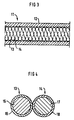
- FIG. 3 an electrode lead 11 consisting of an insulating sleeve 12, a first conductor 13 and a second conductor 14.
- the figure only illustrates a middle section of the electrode lead 11, which has a connector contact at one end for coupling the electrode lead 11 to a stimulation pulse generator (not shown) such as a pacemaker, and at least one stimulation electrode at its other end for delivering stimulation pulses from the stimulation pulse generator to surrounding tissue, such as a heart.
- a stimulation pulse generator not shown
- stimulation electrode such as a pacemaker
- the first conductor 13 and the second conductor 14 have the cross-section shown in FIG. 4.
- the first conductor 13 comprises a conductor wire 15 with an electrically insulating and abrasion-resistant coating 16.
- the second conductor 14 is composed of a conductor wire 17 and an electrically insulating and abrasion-resistant coating 18.
- the purpose of the electrically insulating and abrasion-resistant coatings 16, 18 is to insulate the conductor wires 15, 17 from one another and minimize the risk of any short-circuit occurring because the layers wear off when the conductors 13, 14 rub against each other.
- the electrically insulating and abrasion-resistant layers 16, 18 are only a few micrometers thick and made of D.L.C. (diamond-like carbon).
Landscapes
- Health & Medical Sciences (AREA)
- Radiology & Medical Imaging (AREA)
- General Health & Medical Sciences (AREA)
- Cardiology (AREA)
- Heart & Thoracic Surgery (AREA)
- Engineering & Computer Science (AREA)
- Biomedical Technology (AREA)
- Inorganic Chemistry (AREA)
- Life Sciences & Earth Sciences (AREA)
- Nuclear Medicine, Radiotherapy & Molecular Imaging (AREA)
- Animal Behavior & Ethology (AREA)
- Chemical & Material Sciences (AREA)
- Public Health (AREA)
- Veterinary Medicine (AREA)
- Electrotherapy Devices (AREA)
- Insulated Conductors (AREA)
Claims (8)
- Eine mehrpolige Elektrodenleitung (1; 11) für ein medizinisches Gerät, ausgebildet, um Stimulationsimpulse an lebendes Gewebe abzugeben, welche Elektrodenleitung (1; 11) einen isolierenden Mantel (2; 12) aufweist, in dem zumindest ein erster Leiter (3; 13) und ein zweiter Leiter (4; 14) gewickelt sind, wobei zumindest der erste Leiter (3; 13) von einer Schicht (6; 16) bedeckt ist, die entweder:eine erste, elektrisch isolierende Lage (6) und eine zweite, äußere, abriebsresistente Lage (7), die kein Polymer ist, odereine einzige, elektrisch isolierende Lage (16), die auch abriebsresistent und kein Polymer ist, aufweist.
- Eine Elektrodenleitung nach Anspruch 1, bei der die zumindest erste und zweite Leiter (3; 13; 4; 14) von der selben elektrisch isolierenden und abriebsresistenten Schicht (6,7;9,10;16;18) bedeckt sind.
- Eine Elektrodenleitung nach einem der Ansprüche 1 oder 2, bei der die elektrisch isolierende und abriebsresistente Schicht (16, 18) aus dem Material D.L.C. ( diamond-like carbon) hergestellt ist.
- Eine Elektrodenleitung nach Anspruch 3, bei der die elektrisch isolierende und abriebsresistente Schicht (16, 18) in einer Lage mit einer Dicke von 0.1 bis 10 µm, vorzugsweise zwischen 1 und 5 µm, aufgetragen ist.
- Eine Elektrodenleitung nach Anspruch 1 oder 2, bei der die isolierende Schicht (6, 7, 8, 10) eine erste innere Lage (6, 8) aus einem elektrisch isolierendem Material und eine zweite äußere Lage (7, 10) aus einem abriebsresistenten Material aufweist.
- Eine Elektrodenleitung nach Anspruch 5, bei der das elektrisch isolierende Material ein Polymer ist.
- Eine Elektrodenleitung nach einem der Ansprüche 5 oder 6, bei der die abriebsresistente Lage (7, 10) aus einem der Materialien Titannitrid, Aluminiumoxid oder DLC (diamond-like carbon) hergestellt ist.
- Eine Elektrodenleitung nach einem der Ansprüche 5 - 7, bei der die abriebsresistente Lage (7, 10) in einer Dicke von 0.1 bis 10 µm, vorzugsweise zwischen 1 und 5 µm, aufgetragen ist.
Applications Claiming Priority (4)
| Application Number | Priority Date | Filing Date | Title |
|---|---|---|---|
| SE9202351 | 1992-08-14 | ||
| SE9202351A SE9202351D0 (sv) | 1992-08-14 | 1992-08-14 | Flerpolig elektrodledning |
| SE9202824 | 1992-09-30 | ||
| SE9202824A SE9202824D0 (sv) | 1992-09-30 | 1992-09-30 | Flerpolig elektrodledning |
Publications (2)
| Publication Number | Publication Date |
|---|---|
| EP0585553A1 EP0585553A1 (de) | 1994-03-09 |
| EP0585553B1 true EP0585553B1 (de) | 1999-09-15 |
Family
ID=26661494
Family Applications (1)
| Application Number | Title | Priority Date | Filing Date |
|---|---|---|---|
| EP93109790A Expired - Lifetime EP0585553B1 (de) | 1992-08-14 | 1993-06-18 | Mehrpolige Elektrodenleitung |
Country Status (4)
| Country | Link |
|---|---|
| US (1) | US5445859A (de) |
| EP (1) | EP0585553B1 (de) |
| JP (1) | JPH06187839A (de) |
| DE (1) | DE69326404T2 (de) |
Families Citing this family (27)
| Publication number | Priority date | Publication date | Assignee | Title |
|---|---|---|---|---|
| JPH09320352A (ja) * | 1996-05-24 | 1997-12-12 | Nissin Electric Co Ltd | 電線及びその製造方法 |
| US6263930B1 (en) * | 2000-04-11 | 2001-07-24 | Scott A. Wiley | Stump grinder |
| SE0003341D0 (sv) * | 2000-09-18 | 2000-09-18 | St Jude Medical | A coating method |
| US7127286B2 (en) | 2001-02-28 | 2006-10-24 | Second Sight Medical Products, Inc. | Implantable device using ultra-nanocrystalline diamond |
| US6901191B2 (en) * | 2001-11-12 | 2005-05-31 | Corning Cable Systems Llc | High density fiber optic cable |
| US20030216800A1 (en) * | 2002-04-11 | 2003-11-20 | Medtronic, Inc. | Implantable medical device conductor insulation and process for forming |
| US7783365B2 (en) * | 2002-04-11 | 2010-08-24 | Medtronic, Inc. | Implantable medical device conductor insulation and process for forming |
| US7904178B2 (en) * | 2002-04-11 | 2011-03-08 | Medtronic, Inc. | Medical electrical lead body designs incorporating energy dissipating shunt |
| US8396568B2 (en) * | 2002-04-11 | 2013-03-12 | Medtronic, Inc. | Medical electrical lead body designs incorporating energy dissipating shunt |
| US8103358B2 (en) * | 2003-04-04 | 2012-01-24 | Medtronic, Inc. | Mapping guidelet |
| US20040215299A1 (en) * | 2003-04-23 | 2004-10-28 | Medtronic, Inc. | Implantable medical device conductor insulation and process for forming |
| JP5221150B2 (ja) * | 2005-02-01 | 2013-06-26 | セカンド サイト メディカル プロダクツ インコーポレイテッド | 超小型埋め込み型の被覆された装置 |
| US8478423B2 (en) | 2009-04-07 | 2013-07-02 | Boston Scientific Neuromodulation Corporation | Insulator layers for leads of implantable electric stimulation systems and methods of making and using |
| US9014815B2 (en) * | 2009-11-19 | 2015-04-21 | Medtronic, Inc. | Electrode assembly in a medical electrical lead |
| EP2563458A1 (de) | 2010-04-30 | 2013-03-06 | Medtronic, Inc. | Medizinische elektrische zuleitung mit einer energieabschwächenden struktur |
| JP5577469B2 (ja) | 2010-09-15 | 2014-08-20 | カーディアック ペースメイカーズ, インコーポレイテッド | 神経刺激リードのリード構成の自動選択 |
| EP2726142B1 (de) | 2011-06-28 | 2017-05-10 | Cardiac Pacemakers, Inc. | Zugentlastung für die elektrode einer implantierbaren medizinischen vorrichtung |
| US8903509B2 (en) | 2012-03-21 | 2014-12-02 | Cardiac Pacemakers Inc. | Systems and methods for stimulation of vagus nerve |
| US20130296988A1 (en) * | 2012-05-02 | 2013-11-07 | Cardiac Pacemakers, Inc. | Pacing leads with ultrathin isolation layer by atomic layer deposition |
| EP2890414B1 (de) | 2012-08-29 | 2019-01-16 | Cardiac Pacemakers, Inc. | Verbesserte reibungsarme beschichtung für medizinische ableitungen und herstellungsverfahren dafür |
| WO2014055393A1 (en) | 2012-10-02 | 2014-04-10 | Cardiac Pacemakers, Inc. | Pinch to open cuff electrode |
| US9114250B2 (en) | 2012-10-02 | 2015-08-25 | Cardiac Pacemakers, Inc. | Pinch to open cuff electrode |
| US9364662B2 (en) | 2012-11-09 | 2016-06-14 | Cardiac Pacemakers, Inc. | Implantable lead having a lumen with a wear-resistant liner |
| EP2922594B1 (de) | 2012-11-21 | 2018-02-14 | Cardiac Pacemakers, Inc. | Medizinische elektroden mit lagenartigen beschichtungen |
| EP2938396B1 (de) | 2012-12-28 | 2017-02-22 | Cardiac Pacemakers, Inc. | Stimulationsmanschette und implantationsinstrument |
| EP2956208B1 (de) | 2013-02-13 | 2021-01-13 | Cardiac Pacemakers, Inc. | Manschettenelektrode mit integrierter ranke |
| US10953233B2 (en) * | 2016-04-15 | 2021-03-23 | Medtronic, Inc. | Medical device lead assembly with variable pitch coil |
Family Cites Families (8)
| Publication number | Priority date | Publication date | Assignee | Title |
|---|---|---|---|---|
| US3348548A (en) * | 1965-04-26 | 1967-10-24 | William M Chardack | Implantable electrode with stiffening stylet |
| FR2463625A1 (fr) * | 1979-08-23 | 1981-02-27 | Medtronic Inc | Conducteur multipolaire pour stimulateur cardiaque |
| DE3215021A1 (de) * | 1982-04-22 | 1983-10-27 | Siemens AG, 1000 Berlin und 8000 München | Mehrpolige elektrische leitung |
| CH656313A5 (en) * | 1982-05-24 | 1986-06-30 | Straumann Inst Ag | Electrode with an electrical conductor which is connected to a contact provided for forming a connection with tissue |
| US4437474A (en) * | 1982-07-16 | 1984-03-20 | Cordis Corporation | Method for making multiconductor coil and the coil made thereby |
| US4662382A (en) * | 1985-01-16 | 1987-05-05 | Intermedics, Inc. | Pacemaker lead with enhanced sensitivity |
| US4788329A (en) * | 1986-11-03 | 1988-11-29 | American Cyanamid Company | Preparation of cyclohexyl mono- and diurethanes and isocyanates derived therefrom by addition of methylcarbamate to limonene, process and compositions |
| US4947866A (en) * | 1988-02-16 | 1990-08-14 | Medtronic, Inc. | Medical electrical lead |
-
1993
- 1993-06-18 EP EP93109790A patent/EP0585553B1/de not_active Expired - Lifetime
- 1993-06-18 DE DE69326404T patent/DE69326404T2/de not_active Expired - Fee Related
- 1993-08-12 US US08/105,158 patent/US5445859A/en not_active Expired - Lifetime
- 1993-08-13 JP JP5201482A patent/JPH06187839A/ja active Pending
Non-Patent Citations (1)
| Title |
|---|
| PARAT Index of Polymer Trade Names, VCH-Berlin * |
Also Published As
| Publication number | Publication date |
|---|---|
| US5445859A (en) | 1995-08-29 |
| DE69326404T2 (de) | 2000-03-09 |
| DE69326404D1 (de) | 1999-10-21 |
| EP0585553A1 (de) | 1994-03-09 |
| JPH06187839A (ja) | 1994-07-08 |
Similar Documents
| Publication | Publication Date | Title |
|---|---|---|
| EP0585553A1 (de) | Mehrpolige Elektrodenleitung | |
| US5824026A (en) | Catheter for delivery of electric energy and a process for manufacturing same | |
| EP1984069B1 (de) | Medizinische elektrische leitung mit verbesserter induktivität | |
| US5796044A (en) | Coiled wire conductor insulation for biomedical lead | |
| US5897585A (en) | Stretchable pacing lead | |
| EP1948295B1 (de) | Implantierbarer elektrophysiologischer leitungskörper | |
| US4573481A (en) | Implantable electrode array | |
| US6321102B1 (en) | Cardiac lead with minimized inside diameter of sleeve | |
| EP0453117B1 (de) | Poröse Elektrode mit vergrösserter Reaktionsoberfläche | |
| US5483022A (en) | Implantable conductor coil formed from cabled composite wire | |
| US5366496A (en) | Subcutaneous shunted coil electrode | |
| US20030216800A1 (en) | Implantable medical device conductor insulation and process for forming | |
| US6925334B1 (en) | Implantable medical lead having multiple, jointly insulated electrical conductors | |
| US5324328A (en) | Conductor for a defibrillator patch lead | |
| US5928277A (en) | One piece defibrillation lead circuit | |
| AU694332B2 (en) | Cardiac lead with composite insulating structure | |
| US6580949B1 (en) | Implantable electrode lead | |
| JP2001511406A (ja) | 心臓ペースメーカーのケーブルリード | |
| EP2429636B1 (de) | Abschirmung einer implantierbaren medizinischen elektrode | |
| JPS63271908A (ja) | 可撓性遮蔽ケーブル | |
| US20040249430A1 (en) | Implantable medical electrical lead | |
| US6792317B1 (en) | Implantable electric lead and electrical coupling | |
| WO2001091851A1 (en) | Lead with helically wound conductors and distance members | |
| EP2114512B1 (de) | Verfahren zur herstellung einer aktiven befestigungselektrode | |
| GB2316007A (en) | Electrode contact device |
Legal Events
| Date | Code | Title | Description |
|---|---|---|---|
| PUAI | Public reference made under article 153(3) epc to a published international application that has entered the european phase |
Free format text: ORIGINAL CODE: 0009012 |
|
| AK | Designated contracting states |
Kind code of ref document: A1 Designated state(s): DE FR GB IT NL SE |
|
| 17P | Request for examination filed |
Effective date: 19940620 |
|
| RAP1 | Party data changed (applicant data changed or rights of an application transferred) |
Owner name: PACESETTER AB |
|
| 17Q | First examination report despatched |
Effective date: 19951122 |
|
| GRAG | Despatch of communication of intention to grant |
Free format text: ORIGINAL CODE: EPIDOS AGRA |
|
| GRAG | Despatch of communication of intention to grant |
Free format text: ORIGINAL CODE: EPIDOS AGRA |
|
| GRAH | Despatch of communication of intention to grant a patent |
Free format text: ORIGINAL CODE: EPIDOS IGRA |
|
| GRAH | Despatch of communication of intention to grant a patent |
Free format text: ORIGINAL CODE: EPIDOS IGRA |
|
| GRAA | (expected) grant |
Free format text: ORIGINAL CODE: 0009210 |
|
| AK | Designated contracting states |
Kind code of ref document: B1 Designated state(s): DE FR GB IT NL SE |
|
| PG25 | Lapsed in a contracting state [announced via postgrant information from national office to epo] |
Ref country code: SE Free format text: THE PATENT HAS BEEN ANNULLED BY A DECISION OF A NATIONAL AUTHORITY Effective date: 19990915 |
|
| REF | Corresponds to: |
Ref document number: 69326404 Country of ref document: DE Date of ref document: 19991021 |
|
| ET | Fr: translation filed | ||
| ITF | It: translation for a ep patent filed | ||
| PG25 | Lapsed in a contracting state [announced via postgrant information from national office to epo] |
Ref country code: GB Free format text: LAPSE BECAUSE OF NON-PAYMENT OF DUE FEES Effective date: 20000618 |
|
| PLBE | No opposition filed within time limit |
Free format text: ORIGINAL CODE: 0009261 |
|
| STAA | Information on the status of an ep patent application or granted ep patent |
Free format text: STATUS: NO OPPOSITION FILED WITHIN TIME LIMIT |
|
| 26N | No opposition filed | ||
| PG25 | Lapsed in a contracting state [announced via postgrant information from national office to epo] |
Ref country code: NL Free format text: LAPSE BECAUSE OF NON-PAYMENT OF DUE FEES Effective date: 20010101 |
|
| GBPC | Gb: european patent ceased through non-payment of renewal fee |
Effective date: 20000618 |
|
| NLV4 | Nl: lapsed or anulled due to non-payment of the annual fee |
Effective date: 20010101 |
|
| PGFP | Annual fee paid to national office [announced via postgrant information from national office to epo] |
Ref country code: IT Payment date: 20070616 Year of fee payment: 15 |
|
| PG25 | Lapsed in a contracting state [announced via postgrant information from national office to epo] |
Ref country code: IT Free format text: LAPSE BECAUSE OF NON-PAYMENT OF DUE FEES Effective date: 20080618 |
|
| PGFP | Annual fee paid to national office [announced via postgrant information from national office to epo] |
Ref country code: FR Payment date: 20090630 Year of fee payment: 17 |
|
| PGFP | Annual fee paid to national office [announced via postgrant information from national office to epo] |
Ref country code: DE Payment date: 20090626 Year of fee payment: 17 |
|
| REG | Reference to a national code |
Ref country code: FR Ref legal event code: ST Effective date: 20110228 |
|
| PG25 | Lapsed in a contracting state [announced via postgrant information from national office to epo] |
Ref country code: DE Free format text: LAPSE BECAUSE OF NON-PAYMENT OF DUE FEES Effective date: 20110101 |
|
| PG25 | Lapsed in a contracting state [announced via postgrant information from national office to epo] |
Ref country code: FR Free format text: LAPSE BECAUSE OF NON-PAYMENT OF DUE FEES Effective date: 20100630 |