EP0585103B1 - Prozess zur Behandlung einer Suspension von festen Partikeln in einer Trägerflüssigkeit - Google Patents
Prozess zur Behandlung einer Suspension von festen Partikeln in einer Trägerflüssigkeit Download PDFInfo
- Publication number
- EP0585103B1 EP0585103B1 EP93306692A EP93306692A EP0585103B1 EP 0585103 B1 EP0585103 B1 EP 0585103B1 EP 93306692 A EP93306692 A EP 93306692A EP 93306692 A EP93306692 A EP 93306692A EP 0585103 B1 EP0585103 B1 EP 0585103B1
- Authority
- EP
- European Patent Office
- Prior art keywords
- region
- settling
- liquid
- feed
- suspension
- Prior art date
- Legal status (The legal status is an assumption and is not a legal conclusion. Google has not performed a legal analysis and makes no representation as to the accuracy of the status listed.)
- Expired - Lifetime
Links
- 239000007788 liquid Substances 0.000 title claims abstract description 95
- 239000007787 solid Substances 0.000 title claims abstract description 81
- 239000000725 suspension Substances 0.000 title claims abstract description 69
- 239000002245 particle Substances 0.000 title claims abstract description 63
- 238000000034 method Methods 0.000 title claims abstract description 14
- 230000008569 process Effects 0.000 title claims abstract description 14
- 239000002002 slurry Substances 0.000 claims abstract description 65
- 238000005056 compaction Methods 0.000 claims abstract description 51
- 230000037361 pathway Effects 0.000 claims abstract description 39
- 230000005484 gravity Effects 0.000 claims abstract description 22
- XLYOFNOQVPJJNP-UHFFFAOYSA-N water Substances O XLYOFNOQVPJJNP-UHFFFAOYSA-N 0.000 claims description 50
- 230000003311 flocculating effect Effects 0.000 claims description 37
- 230000003068 static effect Effects 0.000 claims description 34
- 238000002156 mixing Methods 0.000 claims description 19
- 238000005189 flocculation Methods 0.000 claims description 7
- 230000016615 flocculation Effects 0.000 claims description 7
- 230000001154 acute effect Effects 0.000 claims description 4
- 230000008719 thickening Effects 0.000 description 20
- 238000005352 clarification Methods 0.000 description 12
- 238000012360 testing method Methods 0.000 description 10
- 238000000926 separation method Methods 0.000 description 9
- 239000002562 thickening agent Substances 0.000 description 9
- 230000001965 increasing effect Effects 0.000 description 7
- 230000000694 effects Effects 0.000 description 6
- OKTJSMMVPCPJKN-UHFFFAOYSA-N Carbon Chemical compound [C] OKTJSMMVPCPJKN-UHFFFAOYSA-N 0.000 description 5
- 238000007596 consolidation process Methods 0.000 description 5
- 239000010802 sludge Substances 0.000 description 5
- 238000009826 distribution Methods 0.000 description 4
- 229920002401 polyacrylamide Polymers 0.000 description 4
- 230000008901 benefit Effects 0.000 description 3
- 230000007423 decrease Effects 0.000 description 3
- 238000007865 diluting Methods 0.000 description 3
- 238000010790 dilution Methods 0.000 description 3
- 239000012895 dilution Substances 0.000 description 3
- 238000012423 maintenance Methods 0.000 description 3
- 239000002244 precipitate Substances 0.000 description 3
- 230000000630 rising effect Effects 0.000 description 3
- 239000010865 sewage Substances 0.000 description 3
- OYPRJOBELJOOCE-UHFFFAOYSA-N Calcium Chemical compound [Ca] OYPRJOBELJOOCE-UHFFFAOYSA-N 0.000 description 2
- 229910052791 calcium Inorganic materials 0.000 description 2
- 239000011575 calcium Substances 0.000 description 2
- 229910052799 carbon Inorganic materials 0.000 description 2
- 239000003245 coal Substances 0.000 description 2
- 239000008119 colloidal silica Substances 0.000 description 2
- 230000001419 dependent effect Effects 0.000 description 2
- 230000002708 enhancing effect Effects 0.000 description 2
- 239000008394 flocculating agent Substances 0.000 description 2
- PCHJSUWPFVWCPO-UHFFFAOYSA-N gold Chemical compound [Au] PCHJSUWPFVWCPO-UHFFFAOYSA-N 0.000 description 2
- 239000010931 gold Substances 0.000 description 2
- 229910052737 gold Inorganic materials 0.000 description 2
- 239000000463 material Substances 0.000 description 2
- 238000005457 optimization Methods 0.000 description 2
- 230000002093 peripheral effect Effects 0.000 description 2
- 239000011148 porous material Substances 0.000 description 2
- 238000001556 precipitation Methods 0.000 description 2
- 238000011084 recovery Methods 0.000 description 2
- 235000008733 Citrus aurantifolia Nutrition 0.000 description 1
- 229920002430 Fibre-reinforced plastic Polymers 0.000 description 1
- VYPSYNLAJGMNEJ-UHFFFAOYSA-N Silicium dioxide Chemical compound O=[Si]=O VYPSYNLAJGMNEJ-UHFFFAOYSA-N 0.000 description 1
- 235000011941 Tilia x europaea Nutrition 0.000 description 1
- 230000015572 biosynthetic process Effects 0.000 description 1
- 230000000903 blocking effect Effects 0.000 description 1
- 230000015556 catabolic process Effects 0.000 description 1
- 238000004891 communication Methods 0.000 description 1
- 238000012937 correction Methods 0.000 description 1
- 230000003247 decreasing effect Effects 0.000 description 1
- 230000000593 degrading effect Effects 0.000 description 1
- 238000013461 design Methods 0.000 description 1
- 230000006866 deterioration Effects 0.000 description 1
- 238000007599 discharging Methods 0.000 description 1
- 230000002349 favourable effect Effects 0.000 description 1
- 239000011151 fibre-reinforced plastic Substances 0.000 description 1
- 239000012530 fluid Substances 0.000 description 1
- 230000002706 hydrostatic effect Effects 0.000 description 1
- 230000006872 improvement Effects 0.000 description 1
- 239000012535 impurity Substances 0.000 description 1
- 239000004571 lime Substances 0.000 description 1
- 238000004519 manufacturing process Methods 0.000 description 1
- 230000002572 peristaltic effect Effects 0.000 description 1
- 238000005086 pumping Methods 0.000 description 1
- 230000008929 regeneration Effects 0.000 description 1
- 238000011069 regeneration method Methods 0.000 description 1
- 230000001105 regulatory effect Effects 0.000 description 1
- 239000002689 soil Substances 0.000 description 1
- 230000003019 stabilising effect Effects 0.000 description 1
Images


Classifications
-
- B—PERFORMING OPERATIONS; TRANSPORTING
- B01—PHYSICAL OR CHEMICAL PROCESSES OR APPARATUS IN GENERAL
- B01D—SEPARATION
- B01D21/00—Separation of suspended solid particles from liquids by sedimentation
- B01D21/24—Feed or discharge mechanisms for settling tanks
- B01D21/2405—Feed mechanisms for settling tanks
- B01D21/2416—Liquid distributors with a plurality of feed points
-
- B—PERFORMING OPERATIONS; TRANSPORTING
- B01—PHYSICAL OR CHEMICAL PROCESSES OR APPARATUS IN GENERAL
- B01D—SEPARATION
- B01D21/00—Separation of suspended solid particles from liquids by sedimentation
- B01D21/0039—Settling tanks provided with contact surfaces, e.g. baffles, particles
- B01D21/0042—Baffles or guide plates
-
- B—PERFORMING OPERATIONS; TRANSPORTING
- B01—PHYSICAL OR CHEMICAL PROCESSES OR APPARATUS IN GENERAL
- B01D—SEPARATION
- B01D21/00—Separation of suspended solid particles from liquids by sedimentation
- B01D21/0039—Settling tanks provided with contact surfaces, e.g. baffles, particles
- B01D21/0045—Plurality of essentially parallel plates
-
- B—PERFORMING OPERATIONS; TRANSPORTING
- B01—PHYSICAL OR CHEMICAL PROCESSES OR APPARATUS IN GENERAL
- B01D—SEPARATION
- B01D21/00—Separation of suspended solid particles from liquids by sedimentation
- B01D21/0039—Settling tanks provided with contact surfaces, e.g. baffles, particles
- B01D21/0057—Settling tanks provided with contact surfaces, e.g. baffles, particles with counter-current flow direction of liquid and solid particles
-
- B—PERFORMING OPERATIONS; TRANSPORTING
- B01—PHYSICAL OR CHEMICAL PROCESSES OR APPARATUS IN GENERAL
- B01D—SEPARATION
- B01D21/00—Separation of suspended solid particles from liquids by sedimentation
- B01D21/02—Settling tanks with single outlets for the separated liquid
-
- B—PERFORMING OPERATIONS; TRANSPORTING
- B01—PHYSICAL OR CHEMICAL PROCESSES OR APPARATUS IN GENERAL
- B01D—SEPARATION
- B01D21/00—Separation of suspended solid particles from liquids by sedimentation
- B01D21/02—Settling tanks with single outlets for the separated liquid
- B01D21/08—Settling tanks with single outlets for the separated liquid provided with flocculating compartments
-
- B—PERFORMING OPERATIONS; TRANSPORTING
- B01—PHYSICAL OR CHEMICAL PROCESSES OR APPARATUS IN GENERAL
- B01D—SEPARATION
- B01D21/00—Separation of suspended solid particles from liquids by sedimentation
- B01D21/24—Feed or discharge mechanisms for settling tanks
- B01D21/2405—Feed mechanisms for settling tanks
-
- B—PERFORMING OPERATIONS; TRANSPORTING
- B01—PHYSICAL OR CHEMICAL PROCESSES OR APPARATUS IN GENERAL
- B01D—SEPARATION
- B01D21/00—Separation of suspended solid particles from liquids by sedimentation
- B01D21/24—Feed or discharge mechanisms for settling tanks
- B01D21/2427—The feed or discharge opening located at a distant position from the side walls
-
- B—PERFORMING OPERATIONS; TRANSPORTING
- B01—PHYSICAL OR CHEMICAL PROCESSES OR APPARATUS IN GENERAL
- B01D—SEPARATION
- B01D21/00—Separation of suspended solid particles from liquids by sedimentation
- B01D21/24—Feed or discharge mechanisms for settling tanks
- B01D21/2444—Discharge mechanisms for the classified liquid
-
- B—PERFORMING OPERATIONS; TRANSPORTING
- B01—PHYSICAL OR CHEMICAL PROCESSES OR APPARATUS IN GENERAL
- B01D—SEPARATION
- B01D21/00—Separation of suspended solid particles from liquids by sedimentation
- B01D21/24—Feed or discharge mechanisms for settling tanks
- B01D21/245—Discharge mechanisms for the sediments
-
- B—PERFORMING OPERATIONS; TRANSPORTING
- B03—SEPARATION OF SOLID MATERIALS USING LIQUIDS OR USING PNEUMATIC TABLES OR JIGS; MAGNETIC OR ELECTROSTATIC SEPARATION OF SOLID MATERIALS FROM SOLID MATERIALS OR FLUIDS; SEPARATION BY HIGH-VOLTAGE ELECTRIC FIELDS
- B03B—SEPARATING SOLID MATERIALS USING LIQUIDS OR USING PNEUMATIC TABLES OR JIGS
- B03B5/00—Washing granular, powdered or lumpy materials; Wet separating
- B03B5/62—Washing granular, powdered or lumpy materials; Wet separating by hydraulic classifiers, e.g. of launder, tank, spiral or helical chute concentrator type
- B03B5/623—Upward current classifiers
-
- B—PERFORMING OPERATIONS; TRANSPORTING
- B03—SEPARATION OF SOLID MATERIALS USING LIQUIDS OR USING PNEUMATIC TABLES OR JIGS; MAGNETIC OR ELECTROSTATIC SEPARATION OF SOLID MATERIALS FROM SOLID MATERIALS OR FLUIDS; SEPARATION BY HIGH-VOLTAGE ELECTRIC FIELDS
- B03B—SEPARATING SOLID MATERIALS USING LIQUIDS OR USING PNEUMATIC TABLES OR JIGS
- B03B5/00—Washing granular, powdered or lumpy materials; Wet separating
- B03B5/62—Washing granular, powdered or lumpy materials; Wet separating by hydraulic classifiers, e.g. of launder, tank, spiral or helical chute concentrator type
- B03B5/66—Washing granular, powdered or lumpy materials; Wet separating by hydraulic classifiers, e.g. of launder, tank, spiral or helical chute concentrator type of the hindered settling type
Definitions
- THIS INVENTION relates to a process for treating a suspension of solid particles in a carrier liquid. It relates also to settling apparatus.
- DE-C-642281 discloses sewage clarification means for domestic sewage.
- the clarification means has an alternately widening and narrowing clarification shaft, a hollow deflecting body in the interior of the shaft, and alternately arranged slits in the sliding surfaces.
- This patent deals with clarification rather than thickening, and the clarification is effected into separate zones, rather than a single zone.
- DE-C-72007 deals with sewage clarification apparatus which has a plurality of superposed clarification chambers which are in communication with one another in their bottom regions. It does not deal with deliquifying a slurry in free settling, hindered settling and compaction zones.
- US-A-2793186 deals with apparatus for classifying fluid suspensions.
- the apparatus utilizes inverted conical baffles, but does not teach their use for dewatering suspensions in free settling, hindered settling and compaction zones.
- a process for treating a suspension of solid particles in a carrier liquid characterized in that it comprises
- the solid particles thus have a higher density than the carrier liquid, and the process thus serves to thicken and deliquify the suspension, thereby forming the slurry. Separation of solid particles from the liquid takes place as the liquid moves along the pathway, thereby clarifying the liquid.
- the gravity settling in the treatment zone is effected under more-or-less quiescent conditions.
- the particles In the free settling region, the particles thus settle independently and in unhindered fashion, with the settling rate mainly dependent on particle size.
- the particles In the hindered settling region, the particles are sufficiently close to one another to restrict or hinder passage or egress of the liquid from between the particles.
- the particle settling rate decreases with increasing concentration of solid particles, and the settling rate is retarded by particle or floc interference.
- the solid particles or flocs are generally in contact with one another, with consolidation or compaction of the slurry taking place in this zone as the intergranular contact pressures between the particles causes them to rearrange in closer formation or to deform.
- the rate at which the slurry thickens depends on, amongst others, the rate at which the liquid can be forced or 'squeezed out' from between the particles.
- the various regions are not necessarily sharply demarcated, and the regions can thus overlap.
- categorize such a treatment zone into four categories: a dilute or Class 1 region; an intermediate or Class 2 region; a concentrated or Class 3 region; and a compact or Class 4 region, with the free settling region referred to above corresponding more-or-less to a combination of the Class 1 and Class 2 regions, the hindered settling region to the Class 3 region, and the compaction region to the Class 4 region.
- such treatment zones have typically been provided by shallow circular tanks with central feeding of the suspension and predominantly horizontal radially outwardly flow within the tanks, and slowly rotating rakes in the hindered settling and compaction zones for moving the compacted sludge towards a central discharge point.
- these tanks have the drawbacks that they are maintenance intensive in view of the moving parts involved and require complicated control equipment to prevent mechanical and electrical overloading should the slurry become too thick to move.
- the ratio of their diameter to their height is large, ie they are shallow large diameter tanks, they do not effectively utilize the principal that the rate of consolidation of a slurry is proportional to the intergranular pressure between the slurry particles, ie low intergranular pressures only are utilized in such tanks.
- the process of the invention thus at least reduces these drawbacks.
- the pathway may also extend into the hindered settling region and optionally even into the free settling region.
- the pathway may be inclined at an acute angle of between 30° and 75° to the horizontal.
- the pathway may be provided along the underside of a continuous or discontinuous static inclined surface located in the compaction region and, optionally, in the hindered settling region, with the surface providing the protection against the settling solid particles.
- the pathway or channel is thus formed in the lee of the static inclined surface relative to the direction of the solids which are settling, ie moving with a vertical downwards component due to gravity settling and/or withdrawal of sludge from below the surfaces.
- the feed zone is located in the free settling region, and the suspension is allowed to move down the feed zone with substantially no mixing thereof with the liquid in the free settling region, from a high level to a lower level.
- the suspension is allowed to exit at the lower level of the feed zone.
- the process may also include subjecting the suspension, at its exit at the lower level of the feed zone, to flocculation in a flocculating sub-region of the free settling region, with clarified liquid passing upwardly from the flocculating sub-region, and liquid containing flocs of the solid particles passing downwardly therefrom.
- the liquid passage or circulation from the pathway or pathways through the conduit(s) thus results from the difference in specific gravities of the liquid in the pathway and in the various regions.
- the Applicant believes that, by keeping the clarified liquid out of contact with quiescent liquid in the compaction and hindered settling regions, disturbance of particles settling in these regions is inhibited, thereby enhancing slurry thickening or consolidation.
- a plurality of the pathways spaced vertically apart, with the liquid from each pathway passing upwardly to the feed zone as a separate stream, may be provided.
- inclined pathways may be provided in both the hindered settling region and the compaction region, and some pathways may extend from the compaction region to the hindered settling region. At least some of the pathways may extend parallel to each other.
- settling apparatus characterized in that it comprises
- a plurality of the static separating members staggered vertically and/or horizontally, may be provided, and the surfaces thereof may, as hereinbefore described, be inclined at an acute angle of between 30° and 75° to the horizontal.
- at least one of the surfaces may extend into the hindered settling region and, optionally, even into the free settling region; alternatively, or additionally, at least one static inclined surface may be provided in the hindered settling region and/or in the free settling region, this surface thus being spaced vertically from the static inclined surface(s) in the compaction region.
- the vessel may comprise an upwardly extending peripheral wall defining the free settling and hindered settling regions, and a lower portion, tapering down from the peripheral wall to a slurry or thickened sludge outlet, with the lower portion defining the compaction region and, possibly, at least a portion of the hindered settling region.
- the location of the various regions in the vessel may vary.
- the compaction region can extend to above the tapered portion of the vessel.
- the vessel may, in particular, be cylindrical with the lower portion being of inverted conical shape, and generally with its height being greater than its diameter.
- the feed means When the feed means comprises the feed cylinder, it may be an upright open-ended feed cylinder.
- the cylinder may extend down to near the bottom of the free settling zone.
- the feed means may comprise the feed means for feeding a suspension into separating apparatus, as described in South African Patent No. 88/0772.
- the apparatus may include a flocculating device connected to the or each feed well suspension discharge outlet, and located above the compaction zone, with the flocculating device adapted to discharge clarified water upwardly and flocculated solids downwardly towards the compaction zone.
- the flocculating device may also be similar to the feed means of South African Patent No. 88/0772.
- the clarified liquid withdrawal means may comprise a nozzle or outlet in the wall of the vessel, an overflow weir, a distribution plate or the like.
- the conduit leads upwardly to direct a liquid flow from an upper edge of at least the uppermost static inclined surface, into the feed well so that, in use, clarified water passes from the underside of the surface over its upper edge, along the conduit, and into the feed well.
- Each separating member may be of hollow open-ended static conical form, with the conical separating members thus being spaced apart vertically and the downwardly facing surfaces of the separating members providing the static inclined surfaces.
- a clarified liquid outlet may then be provided at the apex of each separating member.
- the conduit is thus located around the outlet of the uppermost separating member.
- the apices of the separating members may be upwardly directed, and the separating members may be located concentrically within the vessel. Instead, however, they can be inclined at any other desired angle to the horizontal, as hereinbefore described.
- the conduit may extend upwardly from an upper edge of only the uppermost separating member, and clarified water may then, in use, pass from one inclined surface to the next.
- conduits each leading from the apex of one of the other separating members and terminating with clearance from the separating member immediately above it, may be provided.
- further conduits each leading from the apex of one of the other separating members, into the feed well so that, in use, clarified liquid from each separating member is discharged into the feed well and admixed with feed suspension, may be provided.
- Alternative settling apparatus may provide a plurality of vertically spaced and/or horizontally spaced inclined static separating members in the compaction zone, with downwardly facing surfaces thereof providing the static inclined surfaces.
- the downwardly facing surfaces may be planar, and may be arranged radially in the vessel.
- the separating members may be channel-shaped or angle-shaped located in inverted fashion in the vessel so that they face downwardly. They may then be located parallel to the sides of the conical portion, and may be arranged in radial fashion as hereinbefore described.
- a plurality of 'layers' of the members, with the members of one layer spaced from those of an adjacent layer, and possibly with the members of one layer being staggered circumferentially with respect to those of an adjacent layer, may be provided.
- other alternative settling apparatus may include a plurality of upwardly extending concentrically located static spiral separating members in the compaction region, with downwardly facing surfaces of the spirals providing the static inclined surfaces.
- the separating members may then be arcuate shaped in cross-section with their concave surfaces being downwardly directed, and constituting the static inclined surfaces, so that the water channels extend alongside the concave surfaces.
- reference numeral 10 generally indicates settling apparatus alternative to that according to the invention, for thickening and deliquifying a suspension of solid particles in a carrier liquid.
- the density of the solid particles is greater than that of the liquid.
- the apparatus 10 comprises a vessel generally indicated by reference numeral 12.
- the vessel 12 is circular in plan view and has a cylindrical wall 14 and a lower portion 16 of inverted conical shape.
- a thickened sludge outlet 18 is provided at the apex of the lower portion 16.
- An axially extending feed cylinder 20 is located within the vessel 12, with a suspension feed conduit 22 leading into the feed cylinder.
- a clarified liquid outlet 24 is provided in the wall 14 near its upper end.
- the vessel 12 provides a treatment zone comprising an upper free settling region 26, an intermediate hindered settling region 28, and a lower compaction region 30.
- the region 30 is located within the conical vessel portion 16; however, the regions need not necessarily be exactly as indicated, but can vary in practice. For example, the region 30 can terminate above the vessel portion 16. Moreover, there will, in practice, not necessarily be a sharp demarcation between the regions, with the one region overlapping with an adjacent region.
- the settling apparatus 10 also includes a plurality of static or fixed channel or angle shaped separating members 32 located in inverted fashion in the lower portion 16 of the vessel 12, mounted by means of brackets (not shown) to the vessel.
- the members 32 are arranged radially, and extend parallel to the lower portion 16 of the vessel.
- a number of 'layers' of the members 32 are provided, with the members of one layer being spaced vertically from those of an adjacent layer, and with the members of one layer being staggered circumferentially with respect to those of an adjacent layer. Instead, however, only one layer of the members 32 can be used.
- Each member 32 comprises a pair of sides 34, 36 having downwardly directed inclined planar surfaces 40 defining between them an inclined channel 38 along which the water pathways extend.
- the members 32 are inclined at between 30° and 75° to the horizontal, typically between 45° and 60° to the horizontal.
- a suspension of the solid particles in the carrier liquid enters the vessel 12 through the conduit 22.
- the feed cylinder 20 which extends down to near the bottom of the free settling region 26, the suspension is distributed downwardly and radially outwardly.
- Conditions within the vessel are more-or-less quiescent so that it functions as a gravity settler, ie gravity thickening and deliquifying occurs therein.
- free settling region 26 free settling of the solid particles through the body of liquid takes place.
- the compaction region 30 a slurry is formed, with consolidation or compaction of the slurry taking place due to the intergranular contact pressure between the particles. The pore pressure is reduced, the intergranular pressure is increased, and hence compaction or dewatering of the slurry is enhanced by means of the separating members 32.
- each downwardly directed inclined surface 40 there is provided the inclined water pathway 38 as hereinbefore described and along which liquid can escape upwardly through slurry 50 in the region 30, substantially unhindered by settling solid particles. In this fashion, deliquifying and thickening of the slurry, is enhanced.
- the liquid of the suspension is water
- the solid particles are an impurity such as soil, a precipitate or the like.
- the slurry may be turbid underground water from a gold mine or the like.
- feed means constituted by the components 20, 22
- feed means as described in South African Patent No. 88/0772, which is thus incorporated herein by reference, can be used.
- reference numeral 60 generally indicates settling apparatus alternative to that according to the invention.
- the apparatus 60 includes a plurality of static upwardly extending concentrically located spiral-shaped separating members 62 in the portion 16 of the vessel. Instead, however, only a single separating member 62 may be used.
- the members 62 are arcuate shaped in cross-section and thus have upwardly directed convex surfaces 64 and downwardly directed concave surfaces 66.
- the concave surfaces 66 thus provide the static inclined surfaces along which the water pathways 38 are defined.
- reference numeral 70 generally indicates settling apparatus alternative to that according to the invention.
- the apparatus 70 comprises a plurality of static planar separating members 72 pointing downwardly and inwardly towards the centre of the vessel. As mentioned hereinbefore, they can be located at any other acute angle, typically between 30° and 75°, eg 45° to 60°, to the horizontal.
- the members 72 are also located radially, and can be provided in one or more layers, with the members of one layer being spaced from those of the next layer.
- Each member 72 has an undersurface 74 which is the static inclined surface along which the water pathway 38 is provided.
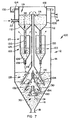
- reference numeral 100 generally indicates settling apparatus, according to a first embodiment of the invention.
- An overflow channel 102 extends peripherally around the upper edge 104 of the cylindrical wall 14, so that the upper edge 104 constitutes a weir.
- the clarified liquid outlet 24 is provided in the channel 102.
- a feed well 106 is located concentrically within the cylindrical wall 14 at the top of the vessel 12, with the upper edge 108 thereof being located at the same level as the upper edge of the channel 102.
- the suspension feed conduit 22 leads into the well 106.
- the floor of the feed well is provided with circular openings, with inverted hollow open-ended conical portions 112 depending downwardly from the feed well floor around these openings. A greater or lesser number of openings and portions 112 can be provided, if desired. For example, only one such opening and portion may be provided.
- a suspension outlet 114 is provided at the apex of each of the conical portions 112.
- a conduit 116 is located axially within the vessel 12 and extends through the centre of the feed well floor.
- the conduit upper end 118 is located at a lower level than the upper edge 108 of the feed well 106.
- the conduit upper end 118 in thus located in a feed or mixing zone 119 provided by the feed well 106.
- the purpose of the conduit 116 will be described in more detail hereunder.
- Each flocculating cylinder 122 comprises a cylindrical wall 124, an inverted hollow open-ended conical shaped lower portion 126 around the lower edge of the wall 124, and a sleeve-like component or restriction pipe 128 depending downwardly from the apex of the conical portion 126 and providing a suspension outlet.
- the ratio of the area enclosed by the cylindrical wall 124 to that of the restriction pipe 128 is typically between 25:1 and 100:1.
- the conduits 120 extend to the level of joints of the walls 124 and conical portions 126 of the flocculating cylinders 122.
- Each of the flocculating cylinders 122 is the same as, or similar to, the feed means described in South African Patent No. 88/0772, which is, as mentioned hereinbefore, incorporated herein by reference.
- the region 30 and a portion of the region 28 may be located within the conical portion 16. Instead, the region 30 may occupy the entire portion 16, and may even extend some way up the cylindrical portion of the vessel 12.
- the feed well 106 and flocculating cylinders 122 are generally located within the region 26.
- the apparatus 100 also includes a plurality of static hollow open-ended truncated conical separating members or dewatering cones 130 spaced apart from each other so that they nestle partly within each other.
- the diameters of the cones 130 decrease from the top downwardly. Instead, their diameters can increase from the bottom upwardly. They can even all be of the same size.
- a greater or lesser number of cones can be provided. For example, a single cone may instead be provided.
- the included angle of the cones is the same, and is between 30° and 75°, preferably between 45° and 65°, typically about 60°.
- a conduit 132 protrudes upwardly from each of the cones 130, around its outlet or opening of its apex, except for the uppermost cone 130 from which the conduit 116 protrudes. The upper end of each conduit 132 terminates with clearance from the cone 130 immediately above it.
- Each cone 130 provides a static circumferentially extending downwardly directed inclined surface 134.
- a suspension of solid particles in carrier liquid enters the mixing zone 119 through the conduit 22.
- the suspension may be a fairly thick slurry, or a liquid containing only a few parts per million suspended solids.
- a flocculant can be added to the mixing zone 119, if desired, in which case the mixing zone may be fitted with a mixer (not shown). Instead, the flocculant can be added to the suspension before it reaches the apparatus 100.
- the suspension is admixed with clarified water passing upwardly along the conduit 116, as described in more detail hereunder.
- the flocculating cylinders 122 are able to operate over a wide range of flow rates. Changes in feed suspended solids levels are also accommodated automatically. At high suspended solids levels collisions are very frequent and the large flocs develop quickly and then escape. At low suspended solids levels collisions are scarce and therefore the hydraulic residence time of the solids inside the flocculating cylinders increases.
- Conditions within the regions 26, 28 and 30 are, as hereinbefore described, more-or-less quiescent so that the vessel 12 functions as a gravity settler, ie gravity thickening and deliquifying occurs therein.
- Clarified liquid which collects at the apices of the cones 130 is transported upwardly first along the conduits 132, and then along the conduit 116, into the mixing zone 119. There it is admixed with the incoming suspension to dilute it.
- Upward movement of clarified water along the conduit 116 is provided by the differences in density or specific gravity of the liquid in the various components.
- the incoming suspension can typically be a suspension of solid particles in water, with the suspension typically having a specific gravity (SG) of about 1,3.
- the SG of the clarified water passing upwardly along the conduit 116 is thus about 1 while the SG of the water in the feed well 106 and the flocculating cylinders 122 as well as in the regions 28, 30 is greater than 1.
- deliquifying and thickening of the slurry takes place in the regions 28, 30, its specific gravity increases, providing a greater driving force urging the clarified water up the conduit 116.
- the feed slurry might have a relative density of, say 1,3.
- the feed/mixing well 106, the conical portions 112, feed pipes or conduits 120 and the lower tapered portions or sections 126 of the flocculating cylinders are filled with slurry.
- the lower part of the vessel 12 is also filled with slurry of increasing density.
- the dewatering discharge conduit or pipe 116 is filled with water, with possibly a few suspended solids.
- the resulting pressure imbalance causes a flow upwards in the dewatering discharge pipe 116. This leads to an accelerated dewatering and thickening of the slurry as the released water is 'pumped' from the cones 130 into the feed/mixing well 106.
- This process is continuous and is powered by the heavy solids which continually enter the top of the vessel 12 and which continually displace water as they drop to the bottom of the unit.
- the dewatering system provided by the cones 130 is self regulating. As water is drawn out of the slurry between the dewatering cones 130 a point is reached when most of the free water has been removed, and light solids are taken up with the water. The solids content of the water in the dewatering discharge pipe 116 increases, the out of balance hydrostatic pressure decreases, the flow slows down, and hydrodynamic equilibrium is reached. At this stage, which is reached within minutes, the dewatering pipe is discharging a thin slurry into the feed/mixing well 106. This dilutes the feed suspension in the well and in the flocculating cylinders, rapidly stabilising the flow pattern.
- This internal recycle also has effects other than merely accelerating the dewatering and thickening of the slurry.
- the first effect is due partly to already flocculated solids being mixed with the incoming suspension in the feed/mixing well. This results in savings in flocculants as the flocculated solids naturally already contain flocculant. The dilution of the feed slurry, even with clear water, results in further substantial savings in the costs of flocculants. This effect is related to the better distribution of flocculant in a more dilute suspension.
- the improvement in the efficiency of the operation of the flocculating cylinders 122 is the improvement in the efficiency of the operation of the flocculating cylinders 122.
- the lower apparent viscosity allows the water to separate from the solids, a proper floc bed is formed and the water exits from the top of the flocculating cylinders whilst the large flocs are discharged, as and when they are large enough, through the lower tapered restriction pipes 128.
- the level of the liquid in the mixing zone 119 will on start-up, assuming that the vessel 12 is filled entirely with substantially clear water, be opposite the upper edge 104 of the wall 14. However, once equilibrium has been achieved within the system with thickened slurry being withdrawn continuously through the outlet 18, suspension being fed continuously through the inlet 22 and clarified water being withdrawn continuously through the outlet 24, the level in the mixing zone 119 will be as indicated in the drawing.
- the apparatus 100 can also be used for the clarification and thickening of liquids containing only a few parts per million of suspended solids.
- the difference in density between the slurry in the feed/mixing well 106, feed pipes 120 and flocculating cylinders 122 and the liquid in the dewatering discharge pipe 116 is very small, and this part of the system provides very little 'pumping' or accelerated thickening effect.
- the suspended solids gradually build up in the lower conical portion 16 of the vessel 12 and as this slurry is dewatered underneath the cones 130, a difference in density is gradually built up between the slurry around the dewatering cones and the central dewatering discharge pipe 116, which is filled with liquid.
- the effect is to drive this liquid up the discharge pipe and into the feed/mixing well while more slurry enters underneath the cones to take the place of the ejected water and the thickened slurry, which due to its increased density, has dropped further down into the conical portion 16 of the vessel 12.
- liquid exiting from the dewatering cones 130 will pick up solids, increasing the density of the liquid travelling up the dewatering pipe 116 until dynamic equilibrium is reached between the pressures due to the difference in densities and friction losses, mainly in the dewatering pipe.
- the solids content of the liquid exiting from the dewatering pipe could be higher than the solids content of the feed suspension.
- the internal recycle actually increases the suspended solids level.
- the cones 130 may be inverted, with an annular clarified water passageway adjacent the vessel wall 14, instead of the conduit 116, then being provided.
- a combination of upwardly directed and inverted cones can also be used, if desired.
- the flocculating cylinders 112 are optional and can be dispensed with if desired. However, it is believed that efficacy is enhanced when using at least one cylinder 122.
- a greater number of flocculating cylinders 122 can be provided, each connected to a conical portion 112 of the feed cylinder. For example, four such cylinders spaced equidistantly apart circumferentially may be provided, and a baffle (not shown) may then be provided between adjacent flocculating cylinders if desired, with the baffles then extending radially outwardly from the conduit 116 to the wall 14. Instead, however, only one flocculating cylinder 122 may be used.
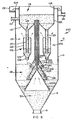
- reference numeral 200 generally indicates settling apparatus according to a second embodiment of the invention.
- the apparatus 200 includes a plurality of static hollow open-ended truncated dewatering cones 202, 204, 206 spaced apart from one another and nestling partly within one another.
- the lowermost cone 206 has the largest cone base diameter, with the uppermost cone 202 having the smallest cone base diameter, ie the diameter of the cones increases from the uppermost cone to the lowermost cone.
- a conduit 208 leads upwardly from the outlet of the cone 202, a conduit 210 from the cone 204, and a conduit 212 from the cone 206.
- the conduits are of different diameters with the conduit 212 located concentrically within the conduit 210, which in turn is located concentrically within the conduit 208.
- Each of the conduits 208, 210, 212 is thus similar to the conduit 116 of the apparatus 190.
- the upper ends of the conduits terminate in the feed well 116.
- the upper cones 204, 202 are 'stepped' to cut down the sloping length of the upper cone surfaces and to provide controlled dewatering beneath each cone as soon as possible after the flocs leave the flocculating cylinders 122. It is believed that dewatering on the upper surface of a large cone could result in the release of trapped water from the slurry as the slurry tumbles down the slope. This released water would pass upwardly against the descending flocs, possibly creating instability of the hindered settling region.
- the apparatus 200 functions in similar fashion to the apparatus 100, save that clarified or partly clarified water from each of the cones 202, 204 and 206 is conveyed separately along a conduit to the feed well 106. Thus, dynamic equilibrium is reached independently between each cone/conduit combination and the surrounding settling solids.
- the Applicant believes that with the apparatus 100, 200 in which the conduits 116, 208, 210, 212 ensure that upwardly flowing clarified water does not disturb the quiescent settling conditions in the regions 26, 28 and 30, good separation of solid particles from liquid will be obtained.
- the apparatus 100, 200 act as combined clarifiers and accelerated thickeners capable of handling very high flow rates and low flocculant dosages to produce clear overflow and high underflow densities.
- the apparatus 100, 200 have no moving parts, and require little maintenance.
- the apparatus included four separating or dewatering members 130.
- the conduits leading from the apices of the separating members were in the form of separate pipes, with the upper end of each pipe terminating in the feed well 106.
- the pilot plant was constructed from fibre reinforced plastics ('FRP') and clear PVC, so that the functioning of the apparatus could be seen clearly.
- the vessel 12 was cylindrical, having a diameter of 477 mm, and its lower portion 16 had an included angle of 60°.
- the total height of the vessel was 4,5 m.
- the diameter of the flocculating cylinder 122 was 300 mm, and it was also fabricated from clear PVC.
- the inside diameter of the restriction pipe 128 was 34 mm.
- each of the separating members 130 was 300 mm, and their included angle was 60°.
- the conduits leading from the apices of each of the members were of 50 mm internal diameter.
- the members 130 were spaced 100 mm apart, measured perpendicularly between the cones.
- Backfill reject material from a dewatering cyclone overflow was fed, at a controlled rate, into the feed well 106 of the pilot plant.
- a non-ionic polyacrylamide was added into the feed chamber to flocculate fine suspended solids in the slurry.
- the feed size distribution of the backfill reject was measured as: % Passing ⁇ 270 ⁇ m 100 ⁇ 75 ⁇ m 75 ⁇ 45 ⁇ m 60 ⁇ 25 ⁇ m 50 ⁇ 16 ⁇ m 40 ⁇ 10 ⁇ m 30
- the pilot plant worked well over a fairly wide range of feed relative density values (1,1 to 1,36) producing acceptable overflow clarities and underflow densities generally above 1,45.
- a slurry of coal fines in water, emanating from an HMS (Heavy Media Separator) plant was fed at a controlled flow rate into the feed well 106 of the pilot plant.
- a non-ionic polyacrylamide was added into the feed chamber to flocculate the fine suspended solids in the feed slurry.
- the pilot plant apparatus was found to be insensitive to feed rate fluctuations and feed density fluctuations. Start-up and stoppages were handled quickly and flexibly, and the apparatus reached operational stability very quickly.
- the feed for this test consist of water containing regenerated carbon fines, colloidal silica and calcium precipitates in various proportions. This stream emanated from the regeneration of activated carbon in a gold recovery stage.
- the solids were present as a suspension in the water.
- the suspension was fed into the feed chamber 106 at a controlled rate.
- a non-ionic polyacrylamide was mixed with the feed suspension to flocculate the fine suspended solids in the feed suspension.
- Clarification and thickening of the feed was found to be highly dependent upon the proportion of fine carbon, colloidal silica and calcium precipitate in the feed.
- ROM (Run of Mine) mill cyclone overflow was fed, at a controlled rate, into the feed chamber 106.
- a non-ionic polyacrylamide was added into the feed chamber to flocculate the fine suspended solids.
- the following results were obtained after optimizing the flocculant dosage: Feed flow rate through the inlet 22 9,17x10 -4 m 3 /sec (3,3m 3 /h) Upflow velocity across the vessel portion 14 5,11x10 -3 m/sec (18,4m/h) Relative density of the feed entering through the inlet 22 1,15 Underflow rate through outlet 18 1,94x10 -4 m 3 /sec (0,7m 3 /h) Relative density of underflow through outlet 18 1,45 to 1,8 Flocculant addition 5mg/kg (g/ton) of solids Suspended solids in clarified water withdrawn through the outlet 24 ⁇ 100mg/dm 3 (mg/l)
Landscapes
- Chemical & Material Sciences (AREA)
- Chemical Kinetics & Catalysis (AREA)
- Solid-Sorbent Or Filter-Aiding Compositions (AREA)
- Separation Of Suspended Particles By Flocculating Agents (AREA)
- Glanulating (AREA)
- Separation Of Solids By Using Liquids Or Pneumatic Power (AREA)
Claims (10)
- Verfahren zur Behandlung einer Suspension fester Partikel in einer Trägerflüssigkeit, dadurch gekennzeichnet, daß es umfaßt:das Zuführen der Suspension in eine Beschickungszone einer Behandlungszone, in welcher die Partikel der Suspension einer Schwerkraftsedimentation unterzogen werden, wobei die Behandlungszone zumindest eine obere Region für eine freie Sedimentation aufweist, in welcher ein freies Sedimentieren fester Partikel durch die Flüssigkeit stattfindet, sowie eine Region für eine behinderte Sedimentation unter der Region für eine freie Sedimentation, in welcher ein behindertes Sedimentieren von Partikeln stattfindet, und eine Verdichtungsregion unter der Region für eine behinderte Sedimentation, in welcher die festen Partikel miteinander in Kontakt sind, so daß in dieser Region eine Aufschlämmung gebildet wird, wobei die Beschickungszone in der Region für eine freie Sedimentation angeordnet ist;das Ableiten einer geklärten Flüssigkeit aus der Region für die freie Sedimentation;das Aufsteigenlassen von Flüssigkeit, zumindest in der Verdichtungsregion, entlang zumindest einem geneigten Pfad, der sich zumindest in der Verdichtungsregion befindet, während sie zumindest teilweise vor sedimentierenden festen Partikeln geschützt ist, wobei jeder Pfad an der Leeseite (in bezug auf die Richtung, in welche die festen Partikel sedimentieren) zumindest eines kontinuierlichen oder diskontinuierlichen, statischen, geneigten Trennelements vorgesehen ist;das Aufsteigenlassen geklärter Flüssigkeit von dem Pfad oder den Pfaden durch eine Leitung oder Leitungen in die Beschickungszone, im wesentlichen ohne deren Vermischung mit Flüssigkeit in der Region für eine freie Sedimentation, aufgrund des Unterschiedes zwischen dem spezifischen Gewicht der aufsteigenden, geklärten Flüssigkeit und jenem der Suspension in der Verdichtungsregion und in den Regionen für freie und behinderte Sedimentation; unddas Ableiten der Aufschlämmung aus der Verdichtungsregion.
- Verfahren nach Anspruch 1, dadurch gekennzeichnet, daß sich der Pfad zumindest auch in die Region für eine behinderte Sedimentation erstreckt und in einem spitzen Winkel von 30° bis 75° zu der Waagerechten geneigt ist, wobei der Pfad entlang der Unterseite einer statischen geneigten Oberfläche vorgesehen ist, die in der Verdichtungsregion und in der Region für eine behinderte Sedimentation angeordnet ist, und wobei die Oberfläche des Trennelements für den Schutz vor sedimentierenden festen Partikeln sorgt.
- Verfahren nach Anspruch 1 oder Anspruch 2, dadurch gekennzeichnet, daß die Beschickungszone in der Region für eine freie Sedimentation angeordnet ist, wobei die Suspension sich in der Beschickungszone von einer hohen Ebene zu einer tiefen Ebene abwärts bewegen kann, ohne im wesentlichen mit der Flüssigkeit in der Region für eine freie Sedimentation vermischt zu werden; und die Suspension an der tiefen Ebene der Beschickungszone in dieselbe Behandlungszone austreten kann.
- Verfahren nach Anspruch 3, dadurch gekennzeichnet, daß es die Flockungsbehandlung der Suspension bei ihrem Austritt an der unteren Ebene aus der Beschickungszone in einer Flockungsteilregion der Region für eine freie Sedimentation umfaßt, wobei geklärte Flüssigkeit aus der Flockungsteilregion aufsteigt und Flüssigkeit, die Flocken der festen Partikel enthält, sich von dort abwärtsbewegt.
- Verfahren nach Anspruch 1, dadurch gekennzeichnet, daß es die Bereitstellung einer Mehrzahl von Pfaden umfaßt, die vertikal voneinander beabstandet sind, wobei eine Flüssigkeit von jedem Pfad als separater Strom zu der Beschickungszone aufsteigt.
- Sedimentationsvorrichtung, dadurch gekennzeichnet, daß sie ein Gefäß umfaßt, das bei Verwendung eine Flüssigkeitsbehandlungszone bereitstellt, die zumindest eine obere Region für eine freie Sedimentation aufweist, in welcher ein freies Sedimentieren fester Partikel in Suspension in einer Flüssigkeit, die in die Flüssigkeitsbehandlungszone eingeleitet wird, durch die Flüssigkeit stattfinden kann, sowie eine Region für eine behinderte Sedimentation unter der Region für eine freie Sedimentation, in welcher ein behindertes Sedimentieren von Partikeln stattfinden kann, und eine Verdichtungsregion unter der Region für eine behinderte Sedimentation, in welcher die festen Partikel miteinander in Kontakt sind, so daß in dieser Region eine Aufschlämmung gebildet wird; sowieBeschickungsmittel zum Zuleiten der Suspension in das Gefäß, wobei die Beschickungsmittel ein Zulaufrohr oder einen Beschickungszylinder umfassen, das/der in der Region für eine freie Sedimentation angeordnet ist und einen Suspensionsabgabeauslaß an seinem Boden aufweist;eine Suspensionszuleitung, die in das Zulaufrohr oder den Beschickungszylinder führt;Ableitungsmittel für geklärte Flüssigkeit zum Ableiten geklärter Flüssigkeit aus der Region für eine freie Sedimentation des Gefäßes;zumindest ein statisches Trennelement mit einer geneigten Oberfläche in zumindest der Verdichtungsregion des Gefäßes, so daß Flüssigkeit entlang einem geneigten Pfad aufsteigen kann, der durch die Unterseite des Elements bereitgestellt wird;eine Leitung oder Leitungen, die einen Durchgang definieren, der in das Zulaufrohr oder den Beschickungszylinder mündet, und bei Verwendung dazu bestimmt ist, Flüssigkeit aus dem Pfad aufzunehmen und diese durch zumindest die Region für eine freie Sedimentation in das Zulaufrohr oder den Beschickungszylinder aufgrund des Unterschiedes zwischen dem spezifischen Gewicht von geklärter Flüssigkeit in dem Pfad und in der/den Leitung(en) und dem spezifischen Gewicht der Suspension in der Verdichtungsregion und in den Regionen für behindertes und freies Sedimentieren zu leiten; undAufschlämmungsableitungsmittel zum Ableiten der Aufschlämmung aus der Verdichtungsregion des Gefäßes.
- Vorrichtung nach Anspruch 6, dadurch gekennzeichnet, daß sie zumindest eine statische geneigte Oberfläche in der Region für eine behinderte Sedimentation enthält, wobei diese Oberfläche vertikal von der statischen geneigten Oberfläche in der Verdichtungsregion beabstandet ist.
- Vorrichtung nach Anspruch 7, dadurch gekennzeichnet, daß sie eine Flockungsvorrichtung enthält, die an den Suspensionsabgabeauslaß des Zulaufrohrs oder des Beschickungszylinders angeschlossen ist und über der Verdichtungsregion angeordnet ist, wobei die Flockungsvorrichtung dazu dient, geklärtes Wasser nach oben und geflockte Feststoffe nach unten zu der Verdichtungsregion abzuleiten.
- Vorrichtung nach Anspruch 7, dadurch gekennzeichnet, daß jede geneigte Oberfläche durch ein hohles, offenendiges, statisches, kegelförmiges Element gebildet ist, wobei die kegelförmigen Elemente somit vertikal voneinander beabstandet sind, und die nach unten weisenden Oberflächen der Elemente die statischen geneigten Oberflächen bilden, und wobei ein Auslaß für geklärte Flüssigkeit an dem Scheitelpunkt jedes Elements vorgesehen ist, und die Leitung somit um den Auslaß der obersten, statischen, geneigten Oberfläche angeordnet ist.
- Vorrichtung nach Anspruch 9, dadurch gekennzeichnet, daß sie eine weitere Leitung enthält, die von dem Scheitelpunkt jedes der anderen kegelförmigen Elemente in das Zulaufrohr führt, so daß bei Verwendung geklärte Flüssigkeit von jedem konischen Element in das Zulaufrohr abgeleitet und der Beschickungssuspension beigemischt wird.
Applications Claiming Priority (4)
| Application Number | Priority Date | Filing Date | Title |
|---|---|---|---|
| ZA926368 | 1992-08-24 | ||
| ZA926368 | 1992-08-24 | ||
| ZA931794 | 1993-03-12 | ||
| ZA931794 | 1993-03-12 |
Publications (3)
| Publication Number | Publication Date |
|---|---|
| EP0585103A2 EP0585103A2 (de) | 1994-03-02 |
| EP0585103A3 EP0585103A3 (en) | 1994-07-06 |
| EP0585103B1 true EP0585103B1 (de) | 2000-05-17 |
Family
ID=27142183
Family Applications (1)
| Application Number | Title | Priority Date | Filing Date |
|---|---|---|---|
| EP93306692A Expired - Lifetime EP0585103B1 (de) | 1992-08-24 | 1993-08-24 | Prozess zur Behandlung einer Suspension von festen Partikeln in einer Trägerflüssigkeit |
Country Status (7)
| Country | Link |
|---|---|
| US (2) | US5433862A (de) |
| EP (1) | EP0585103B1 (de) |
| AT (1) | ATE192942T1 (de) |
| AU (1) | AU667938B2 (de) |
| CA (1) | CA2104648C (de) |
| DE (1) | DE69328655T2 (de) |
| GB (1) | GB2270853B (de) |
Families Citing this family (37)
| Publication number | Priority date | Publication date | Assignee | Title |
|---|---|---|---|---|
| DE4401576A1 (de) * | 1994-01-20 | 1995-07-27 | Bielomatik Leuze & Co | Fremdstoff-Abscheider |
| EP0744984B1 (de) * | 1994-02-16 | 1999-04-07 | Baker Hughes Incorporated | Trennung einer suspension in ihre bestandteile |
| US5589064A (en) * | 1994-10-24 | 1996-12-31 | Elmaleh; Samuel | Apparatus for liquid solid separation of liquid effluents or wastewater |
| AT402817B (de) * | 1995-05-02 | 1997-09-25 | Scheuch Alois Gmbh | Sedimentationsbecken, speziell für kreislaufsysteme |
| AU728638B2 (en) * | 1996-09-12 | 2001-01-11 | Robert Hume Pannell | A thickener or clarifier |
| US5718824A (en) * | 1996-10-01 | 1998-02-17 | Crane Co. | Collector hood for sedimentation tank |
| CA2228072C (en) * | 1997-04-04 | 1999-12-07 | George Ter-Stepanian | Method for settling of suspensions with use of seepage force and vibrations |
| USRE37733E1 (en) * | 1997-04-04 | 2002-06-11 | George Ter-Stepanian | Method for settling of suspensions with use of seepage force and vibrations |
| TW380056B (en) * | 1997-08-25 | 2000-01-21 | Mitsubishi Heavy Industry Kk | Liquid bleeding device and method for controlling the concentration of the slurry in a wet flue gas desulfurization system |
| US6183634B1 (en) * | 1998-04-02 | 2001-02-06 | Bateman Process Equipment Limited | Separator |
| US6328638B1 (en) | 1998-04-28 | 2001-12-11 | Flow International Corporation | Apparatus and methods for recovering abrasive from an abrasive-laden fluid |
| US6299510B1 (en) * | 1998-04-28 | 2001-10-09 | Flow International Corporation | Abrasive removal system for use with high-pressure fluid-jet cutting device |
| ATE285003T1 (de) * | 1998-08-11 | 2005-01-15 | Uli Lippuner | Brunnenstube, und absetzbecken für eine brunnenstube |
| US6250473B1 (en) | 1998-11-17 | 2001-06-26 | Firstenergy Ventures Corp. | Method and apparatus for separating fast settling particles from slow settling particles |
| US6758978B1 (en) | 1999-08-06 | 2004-07-06 | Gl&V Management Hungary Kft. | Deep bed thickener/clarifiers with enhanced liquid removal |
| AU6495000A (en) * | 1999-08-06 | 2001-03-05 | Baker Hughes Incorporated | Deep bed thickener/clarifiers with enhanced liquid removal |
| US20030089650A1 (en) * | 2001-10-02 | 2003-05-15 | Renfro William Leonard | Automatic, renewable separation & filtration system for liquids |
| US6620322B1 (en) * | 2002-06-21 | 2003-09-16 | Smith & Vesio Llc | Apparatus and methods for purifying a waste influent material |
| BRPI0418670B1 (pt) * | 2003-08-29 | 2015-10-20 | Univ Newcastle Res Ass | método de separação de partículas sólidas de uma suspensão comprendendo um líquido e método decontrole da consolidação de um leito de partículas sólidas dentro de um líquido. |
| US7270750B2 (en) | 2005-04-08 | 2007-09-18 | Ecofluid Systems, Inc. | Clarifier recycle system design for use in wastewater treatment system |
| WO2007054912A1 (en) * | 2005-11-10 | 2007-05-18 | Paterson & Cooke Consulting Engineers (Proprietary) Limited | A de-watering apparatus |
| US7547397B1 (en) * | 2007-12-13 | 2009-06-16 | Shi-Ping Liu | Particle-accelerating deposition and separation apparatus and method for turbid water |
| US20100314325A1 (en) * | 2009-06-12 | 2010-12-16 | Palo Alto Research Center Incorporated | Spiral mixer for floc conditioning |
| US8647479B2 (en) * | 2009-06-12 | 2014-02-11 | Palo Alto Research Center Incorporated | Stand-alone integrated water treatment system for distributed water supply to small communities |
| US20100314327A1 (en) * | 2009-06-12 | 2010-12-16 | Palo Alto Research Center Incorporated | Platform technology for industrial separations |
| US20100314323A1 (en) * | 2009-06-12 | 2010-12-16 | Palo Alto Research Center Incorporated | Method and apparatus for continuous flow membrane-less algae dewatering |
| US8152998B2 (en) * | 2010-05-28 | 2012-04-10 | Ashbrook Simon-Hartley, LP | Screenless granular media filters and methods of use |
| CN102267751B (zh) * | 2010-10-26 | 2013-11-20 | 苏木清 | 一种尾矿污水快速沉淀浓缩罐 |
| GB2486173B (en) * | 2010-12-01 | 2017-02-01 | Adey Holdings 2008 Ltd | Separator |
| GB2508257B (en) | 2010-12-01 | 2014-07-23 | Adey Holdings 2008 Ltd | Water and dirt separator |
| US10343088B2 (en) | 2015-02-27 | 2019-07-09 | Recovered Energy, Inc. | Liquid refinement |
| EP3261777A4 (de) | 2015-02-27 | 2019-03-20 | Recovered Energy, Inc. | Flüssigkeitsraffinierung |
| US10343089B2 (en) | 2015-02-27 | 2019-07-09 | Recovered Energy, Inc. | Liquid refinement |
| RU2706650C2 (ru) * | 2015-07-03 | 2019-11-19 | Паквес И.П. Б.В. | Устройство и способ для очистки текучей среды посредством фильтрующего слоя |
| EP3181220A1 (de) * | 2015-12-16 | 2017-06-21 | Basf Se | Verfahren zur entfernung eines heterogenen katalysators aus einem reaktionsprodukt und verfahren zur herstellung eines aromatischen amins |
| CN112445136B (zh) * | 2020-12-16 | 2022-02-22 | 北京科技大学 | 一种基于连续时间神经网络的浓密机预测控制方法及系统 |
| CN113908594A (zh) * | 2021-10-12 | 2022-01-11 | 怀化辰州机械有限责任公司 | 一种尾矿浆沉淀分离及再造方法 |
Family Cites Families (22)
| Publication number | Priority date | Publication date | Assignee | Title |
|---|---|---|---|---|
| US973357A (en) * | 1910-07-23 | 1910-10-18 | Robert S Lewis | Settling-tank. |
| US1262076A (en) * | 1917-07-02 | 1918-04-09 | Archibald B Marston | Turpentine-separator. |
| US1339682A (en) * | 1917-07-03 | 1920-05-11 | Allen Charles | Settling-basin separating device |
| US1526197A (en) * | 1923-08-18 | 1925-02-10 | Ahlqvist Harald | Clarification process and apparatus |
| FR636252A (de) * | 1927-02-03 | 1928-04-05 | ||
| GB427013A (en) * | 1933-07-08 | 1935-04-12 | Robert Schwanda | Improvements in and relating to the separation of specifically lighter and heavier components from liquid or gaseous mixtures |
| GB435954A (en) * | 1934-08-29 | 1935-10-02 | Forderanlagen Ernst Heckel Mit | Apparatus for clarifying coal slurry and the like |
| DE642281C (de) * | 1934-11-02 | 1937-02-27 | Hera Franziska Heider | Klaervorrichtung fuer Hausabwaesser |
| US2793186A (en) * | 1954-01-08 | 1957-05-21 | Ca Nat Research Council | Apparatus for classifying or settling fluid suspensions |
| US2874850A (en) * | 1954-06-22 | 1959-02-24 | Henry Arthur John Silley | Apparatus for separating oil and water |
| AT244358B (de) * | 1961-11-09 | 1966-01-10 | Siegener Ag Geisweid | Absetzgefäß zum Abscheiden von Feststoffen aus einer Trübe |
| US4014791A (en) * | 1972-09-25 | 1977-03-29 | Tuttle Ralph L | Oil separator |
| US4011163A (en) * | 1975-06-19 | 1977-03-08 | Fairbanks Fred A | Water waste treatment |
| US4197201A (en) * | 1976-03-03 | 1980-04-08 | Rederiaktiebolaget Nordstjernan | Apparatus for the filtration of a suspension or emulsion |
| CA1091593A (en) * | 1977-10-05 | 1980-12-16 | Eli I. Robinsky | Gravitational separator having membrane baffles therein |
| US4151084A (en) * | 1977-10-06 | 1979-04-24 | Water Purification Associates | Lamella separators |
| CA1074263A (en) * | 1978-07-31 | 1980-03-25 | Lorne M. Ross | Tri-channel placer mining sluice box separator |
| DE3028686C2 (de) * | 1980-07-29 | 1983-07-14 | Buckau-Walther AG, 4048 Grevenbroich | Vorrichtung zum Waschen von Schüttgut |
| US4451359A (en) * | 1982-03-30 | 1984-05-29 | Daniel Osterberg | Hydraulic flow distributor in gold separator and method |
| ZW17087A1 (en) * | 1986-09-11 | 1987-12-02 | Gold Fields Mining & Dev Ltd | Pulp thickeners |
| FI81269C (fi) * | 1987-09-14 | 1990-10-10 | Ahlstroem Oy | Klargoerare med filtrerande baedd. |
| CA1315703C (en) * | 1989-09-29 | 1993-04-06 | Robert Cyr | Apparatus for the decantation treatment of liquid containing therein suspended material |
-
1993
- 1993-08-23 CA CA002104648A patent/CA2104648C/en not_active Expired - Lifetime
- 1993-08-23 US US08/110,436 patent/US5433862A/en not_active Expired - Lifetime
- 1993-08-24 AT AT93306692T patent/ATE192942T1/de not_active IP Right Cessation
- 1993-08-24 GB GB9317544A patent/GB2270853B/en not_active Expired - Lifetime
- 1993-08-24 AU AU44843/93A patent/AU667938B2/en not_active Expired
- 1993-08-24 EP EP93306692A patent/EP0585103B1/de not_active Expired - Lifetime
- 1993-08-24 DE DE69328655T patent/DE69328655T2/de not_active Expired - Fee Related
-
1995
- 1995-03-17 US US08/406,511 patent/US5549827A/en not_active Expired - Lifetime
Also Published As
| Publication number | Publication date |
|---|---|
| EP0585103A2 (de) | 1994-03-02 |
| GB2270853B (en) | 1997-03-12 |
| DE69328655D1 (de) | 2000-06-21 |
| GB9317544D0 (en) | 1993-10-06 |
| EP0585103A3 (en) | 1994-07-06 |
| DE69328655T2 (de) | 2001-01-11 |
| AU667938B2 (en) | 1996-04-18 |
| AU4484393A (en) | 1994-03-03 |
| US5549827A (en) | 1996-08-27 |
| ATE192942T1 (de) | 2000-06-15 |
| US5433862A (en) | 1995-07-18 |
| GB2270853A (en) | 1994-03-30 |
| CA2104648A1 (en) | 1994-02-25 |
| CA2104648C (en) | 2000-06-20 |
Similar Documents
| Publication | Publication Date | Title |
|---|---|---|
| EP0585103B1 (de) | Prozess zur Behandlung einer Suspension von festen Partikeln in einer Trägerflüssigkeit | |
| US5730864A (en) | Installation for treating an untreated flow by simple sedimentation after ballasting with fine sand | |
| US5840195A (en) | Method and installation for treating an untreated flow by simple sedimentation after ballasting with fine sand | |
| US8021559B2 (en) | Thickening apparatus and method for thickening | |
| US8540887B2 (en) | Feedwells | |
| US4054514A (en) | Sedimentation apparatus with flocculating feed well | |
| EP0162650A2 (de) | Trennung von Bestandteilen aus einer fliessenden Mischung | |
| AU2012296191B2 (en) | Deaeration apparatus and method | |
| US20030173289A1 (en) | Self diluting feedwell including a vertical eduction mechanism and method of dilution employing same | |
| EA004962B1 (ru) | Способ и устройство для осветления и/или загустевания суспензии | |
| EP0354744B1 (de) | Klärungsanlage | |
| EP0744984B1 (de) | Trennung einer suspension in ihre bestandteile | |
| RU2535709C2 (ru) | Способ оптимизации распределения подачи в отстойном резервуаре | |
| US4009106A (en) | Clarifier with overflow scum removal | |
| JPH01107813A (ja) | 濾床型浄化装置 | |
| JP2002058914A (ja) | 固液分離装置 | |
| CA1111782A (en) | Apparatus and method for the gravity settling of suspended solids | |
| WO2000012192A1 (en) | Apparatus for the separation of solids and liquids | |
| NO773680L (no) | Fremgangsmaate ved separasjon av suspendert faststoff fra vaesker | |
| US7270750B2 (en) | Clarifier recycle system design for use in wastewater treatment system | |
| US4218325A (en) | Apparatus for separation of suspensions | |
| RU234278U1 (ru) | Двухконтурный питающий колодец радиального сгустителя | |
| EP0814886A1 (de) | Flüssigkeits-feststoffabscheider | |
| SU1766451A1 (ru) | Способ сгущени суспензий и аппарат дл его осуществлени | |
| RU2275968C1 (ru) | Пневматическая флотационная машина |
Legal Events
| Date | Code | Title | Description |
|---|---|---|---|
| PUAI | Public reference made under article 153(3) epc to a published international application that has entered the european phase |
Free format text: ORIGINAL CODE: 0009012 |
|
| AK | Designated contracting states |
Kind code of ref document: A2 Designated state(s): AT BE CH DE DK ES FR GB IE IT LI LU MC NL PT SE |
|
| PUAL | Search report despatched |
Free format text: ORIGINAL CODE: 0009013 |
|
| AK | Designated contracting states |
Kind code of ref document: A3 Designated state(s): AT BE CH DE DK ES FR GB IE IT LI LU MC NL PT SE |
|
| 17P | Request for examination filed |
Effective date: 19941214 |
|
| 17Q | First examination report despatched |
Effective date: 19950526 |
|
| RAP1 | Party data changed (applicant data changed or rights of an application transferred) |
Owner name: BAKER HUGHES INCORPORATED |
|
| GRAG | Despatch of communication of intention to grant |
Free format text: ORIGINAL CODE: EPIDOS AGRA |
|
| GRAG | Despatch of communication of intention to grant |
Free format text: ORIGINAL CODE: EPIDOS AGRA |
|
| GRAH | Despatch of communication of intention to grant a patent |
Free format text: ORIGINAL CODE: EPIDOS IGRA |
|
| GRAH | Despatch of communication of intention to grant a patent |
Free format text: ORIGINAL CODE: EPIDOS IGRA |
|
| GRAA | (expected) grant |
Free format text: ORIGINAL CODE: 0009210 |
|
| RBV | Designated contracting states (corrected) |
Designated state(s): AT BE CH DE DK ES FR IE IT LI LU MC NL PT SE |
|
| AK | Designated contracting states |
Kind code of ref document: B1 Designated state(s): AT BE CH DE DK ES FR IE IT LI LU MC NL PT SE |
|
| PG25 | Lapsed in a contracting state [announced via postgrant information from national office to epo] |
Ref country code: NL Free format text: LAPSE BECAUSE OF FAILURE TO SUBMIT A TRANSLATION OF THE DESCRIPTION OR TO PAY THE FEE WITHIN THE PRESCRIBED TIME-LIMIT Effective date: 20000517 Ref country code: LI Free format text: LAPSE BECAUSE OF FAILURE TO SUBMIT A TRANSLATION OF THE DESCRIPTION OR TO PAY THE FEE WITHIN THE PRESCRIBED TIME-LIMIT Effective date: 20000517 Ref country code: IT Free format text: LAPSE BECAUSE OF FAILURE TO SUBMIT A TRANSLATION OF THE DESCRIPTION OR TO PAY THE FEE WITHIN THE PRESCRIBED TIME-LIMIT;WARNING: LAPSES OF ITALIAN PATENTS WITH EFFECTIVE DATE BEFORE 2007 MAY HAVE OCCURRED AT ANY TIME BEFORE 2007. THE CORRECT EFFECTIVE DATE MAY BE DIFFERENT FROM THE ONE RECORDED. Effective date: 20000517 Ref country code: ES Free format text: THE PATENT HAS BEEN ANNULLED BY A DECISION OF A NATIONAL AUTHORITY Effective date: 20000517 Ref country code: CH Free format text: LAPSE BECAUSE OF FAILURE TO SUBMIT A TRANSLATION OF THE DESCRIPTION OR TO PAY THE FEE WITHIN THE PRESCRIBED TIME-LIMIT Effective date: 20000517 Ref country code: BE Free format text: LAPSE BECAUSE OF FAILURE TO SUBMIT A TRANSLATION OF THE DESCRIPTION OR TO PAY THE FEE WITHIN THE PRESCRIBED TIME-LIMIT Effective date: 20000517 Ref country code: AT Free format text: LAPSE BECAUSE OF FAILURE TO SUBMIT A TRANSLATION OF THE DESCRIPTION OR TO PAY THE FEE WITHIN THE PRESCRIBED TIME-LIMIT Effective date: 20000517 |
|
| REF | Corresponds to: |
Ref document number: 192942 Country of ref document: AT Date of ref document: 20000615 Kind code of ref document: T |
|
| REG | Reference to a national code |
Ref country code: IE Ref legal event code: FG4D Ref country code: CH Ref legal event code: EP |
|
| REF | Corresponds to: |
Ref document number: 69328655 Country of ref document: DE Date of ref document: 20000621 |
|
| PG25 | Lapsed in a contracting state [announced via postgrant information from national office to epo] |
Ref country code: PT Free format text: LAPSE BECAUSE OF FAILURE TO SUBMIT A TRANSLATION OF THE DESCRIPTION OR TO PAY THE FEE WITHIN THE PRESCRIBED TIME-LIMIT Effective date: 20000817 Ref country code: DK Free format text: LAPSE BECAUSE OF FAILURE TO SUBMIT A TRANSLATION OF THE DESCRIPTION OR TO PAY THE FEE WITHIN THE PRESCRIBED TIME-LIMIT Effective date: 20000817 |
|
| PG25 | Lapsed in a contracting state [announced via postgrant information from national office to epo] |
Ref country code: LU Free format text: LAPSE BECAUSE OF NON-PAYMENT OF DUE FEES Effective date: 20000824 Ref country code: IE Free format text: LAPSE BECAUSE OF NON-PAYMENT OF DUE FEES Effective date: 20000824 |
|
| PG25 | Lapsed in a contracting state [announced via postgrant information from national office to epo] |
Ref country code: MC Free format text: THE PATENT HAS BEEN ANNULLED BY A DECISION OF A NATIONAL AUTHORITY Effective date: 20000831 |
|
| ET | Fr: translation filed | ||
| NLV1 | Nl: lapsed or annulled due to failure to fulfill the requirements of art. 29p and 29m of the patents act | ||
| REG | Reference to a national code |
Ref country code: CH Ref legal event code: PL |
|
| PLBE | No opposition filed within time limit |
Free format text: ORIGINAL CODE: 0009261 |
|
| STAA | Information on the status of an ep patent application or granted ep patent |
Free format text: STATUS: NO OPPOSITION FILED WITHIN TIME LIMIT |
|
| 26N | No opposition filed | ||
| REG | Reference to a national code |
Ref country code: IE Ref legal event code: MM4A |
|
| PGFP | Annual fee paid to national office [announced via postgrant information from national office to epo] |
Ref country code: FR Payment date: 20020731 Year of fee payment: 10 |
|
| PGFP | Annual fee paid to national office [announced via postgrant information from national office to epo] |
Ref country code: SE Payment date: 20020801 Year of fee payment: 10 |
|
| PGFP | Annual fee paid to national office [announced via postgrant information from national office to epo] |
Ref country code: DE Payment date: 20020830 Year of fee payment: 10 |
|
| PG25 | Lapsed in a contracting state [announced via postgrant information from national office to epo] |
Ref country code: SE Free format text: LAPSE BECAUSE OF NON-PAYMENT OF DUE FEES Effective date: 20030825 |
|
| PG25 | Lapsed in a contracting state [announced via postgrant information from national office to epo] |
Ref country code: DE Free format text: LAPSE BECAUSE OF NON-PAYMENT OF DUE FEES Effective date: 20040302 |
|
| EUG | Se: european patent has lapsed | ||
| PG25 | Lapsed in a contracting state [announced via postgrant information from national office to epo] |
Ref country code: FR Free format text: LAPSE BECAUSE OF NON-PAYMENT OF DUE FEES Effective date: 20040430 |
|
| REG | Reference to a national code |
Ref country code: FR Ref legal event code: ST |