EP0584689A2 - Servo brake booster - Google Patents
Servo brake booster Download PDFInfo
- Publication number
- EP0584689A2 EP0584689A2 EP93113109A EP93113109A EP0584689A2 EP 0584689 A2 EP0584689 A2 EP 0584689A2 EP 93113109 A EP93113109 A EP 93113109A EP 93113109 A EP93113109 A EP 93113109A EP 0584689 A2 EP0584689 A2 EP 0584689A2
- Authority
- EP
- European Patent Office
- Prior art keywords
- pressure
- valve
- chamber
- vacuum
- source
- Prior art date
- Legal status (The legal status is an assumption and is not a legal conclusion. Google has not performed a legal analysis and makes no representation as to the accuracy of the status listed.)
- Withdrawn
Links
- 238000011144 upstream manufacturing Methods 0.000 abstract description 3
- 230000007704 transition Effects 0.000 description 2
- 230000003321 amplification Effects 0.000 description 1
- 230000015556 catabolic process Effects 0.000 description 1
- 238000006243 chemical reaction Methods 0.000 description 1
- 238000010276 construction Methods 0.000 description 1
- 238000006073 displacement reaction Methods 0.000 description 1
- 238000005516 engineering process Methods 0.000 description 1
- 238000003199 nucleic acid amplification method Methods 0.000 description 1
- 230000000644 propagated effect Effects 0.000 description 1
- 230000003014 reinforcing effect Effects 0.000 description 1
Images


Classifications
-
- B—PERFORMING OPERATIONS; TRANSPORTING
- B60—VEHICLES IN GENERAL
- B60T—VEHICLE BRAKE CONTROL SYSTEMS OR PARTS THEREOF; BRAKE CONTROL SYSTEMS OR PARTS THEREOF, IN GENERAL; ARRANGEMENT OF BRAKING ELEMENTS ON VEHICLES IN GENERAL; PORTABLE DEVICES FOR PREVENTING UNWANTED MOVEMENT OF VEHICLES; VEHICLE MODIFICATIONS TO FACILITATE COOLING OF BRAKES
- B60T13/00—Transmitting braking action from initiating means to ultimate brake actuator with power assistance or drive; Brake systems incorporating such transmitting means, e.g. air-pressure brake systems
- B60T13/10—Transmitting braking action from initiating means to ultimate brake actuator with power assistance or drive; Brake systems incorporating such transmitting means, e.g. air-pressure brake systems with fluid assistance, drive, or release
- B60T13/24—Transmitting braking action from initiating means to ultimate brake actuator with power assistance or drive; Brake systems incorporating such transmitting means, e.g. air-pressure brake systems with fluid assistance, drive, or release the fluid being gaseous
- B60T13/46—Vacuum systems
- B60T13/52—Vacuum systems indirect, i.e. vacuum booster units
- B60T13/57—Vacuum systems indirect, i.e. vacuum booster units characterised by constructional features of control valves
-
- B—PERFORMING OPERATIONS; TRANSPORTING
- B60—VEHICLES IN GENERAL
- B60T—VEHICLE BRAKE CONTROL SYSTEMS OR PARTS THEREOF; BRAKE CONTROL SYSTEMS OR PARTS THEREOF, IN GENERAL; ARRANGEMENT OF BRAKING ELEMENTS ON VEHICLES IN GENERAL; PORTABLE DEVICES FOR PREVENTING UNWANTED MOVEMENT OF VEHICLES; VEHICLE MODIFICATIONS TO FACILITATE COOLING OF BRAKES
- B60T13/00—Transmitting braking action from initiating means to ultimate brake actuator with power assistance or drive; Brake systems incorporating such transmitting means, e.g. air-pressure brake systems
- B60T13/10—Transmitting braking action from initiating means to ultimate brake actuator with power assistance or drive; Brake systems incorporating such transmitting means, e.g. air-pressure brake systems with fluid assistance, drive, or release
- B60T13/24—Transmitting braking action from initiating means to ultimate brake actuator with power assistance or drive; Brake systems incorporating such transmitting means, e.g. air-pressure brake systems with fluid assistance, drive, or release the fluid being gaseous
- B60T13/46—Vacuum systems
- B60T13/52—Vacuum systems indirect, i.e. vacuum booster units
Definitions
- the invention relates to a brake booster for a vehicle brake system with a two-chamber vacuum booster, the negative pressure chamber is evacuated when the brake force is increased, while in the positive pressure chamber a higher pressure than in the negative pressure chamber can be set by means of a control valve, the higher pressure corresponding at least to the external atmospheric pressure.
- Such brake boosters are generally known to the person skilled in the art (cf. e.g. DE-GM 92 02 154.9).
- the vacuum chamber is usually set to a value of e.g. 0.2 bar evacuated, while in the pressure chamber, depending on the desired reinforcing effect, pressures between 0.2 bar and 1 bar are set.
- the gain that can be achieved with a conventional brake booster of this type corresponds to a pressure difference of approximately 0.8 bar.
- JP 59-134 047 A Patents Abstracts of Japan, Section M, Vol. 8, 1984, No. 262 (11-341)
- a brake booster with the features of the preamble of the claim is known.
- the operation of the brake booster is switched to a state in which pressure is fed into the overpressure chamber of the brake booster, which has a higher pressure than atmospheric pressure, with losses with respect to the compressed air.
- air is lost from the pressure source.
- this loss of compressed air is unavoidable because a slide valve is provided which, for safety and functional reasons, has to assume an intermediate position when switching, in which the compressed air source and the inlet of the valve leading to the outside atmosphere are temporarily connected.
- EP 0 368 691 A1 also describes a brake booster in which a pressure source is used with which air can be fed into the booster which has a higher pressure than the external atmosphere.
- a pressure source is used with which air can be fed into the booster which has a higher pressure than the external atmosphere.
- the supply of compressed air is controlled completely separately, i.e. independent of the supply of air into the pressure chamber of the brake booster at pressures below atmospheric pressure.
- this prior art has the disadvantage that only a limited ring section (bellows) is acted upon by the compressed air, as a result of which the brake booster has a relatively large overall size.
- the invention sets itself the goal of designing a brake booster, which has the features of the preamble of the claim, in such a way that, with high functional reliability, simple construction and small size, it is ensured that the air from the pressure source is used with as little loss as possible.
- control valve The purely mechanical valve according to the invention (hereinafter referred to as "control valve") thus uses the pressure in the pressure chamber of the vacuum booster as a control variable for its self-control, the control being carried out by comparing the instantaneous pressure in the pressure booster chamber of the vacuum booster with the pressure in the external atmosphere (atmospheric pressure) is carried out. According to this control (opening and closing) of the valve, excess pressure (that is to say a pressure which is greater than the external atmospheric pressure) is then introduced into the overpressure chamber of the vacuum booster when atmospheric pressure has been reached in the overpressure chamber. This allows “seamless”, i.e.
- a conventional vacuum amplifier is preferably used, which is assumed to be known here.
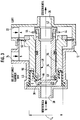
- FIG. 1 shows a conventional brake booster 10 (cf., for example, DE-GM 92 02 154.9), with an overpressure chamber 14 and a vacuum chamber 16.
- a vacuum is generated in a conventional manner, which can typically be about 0.2 bar .
- a pressure source 18 in this sense means a source that generates air whose pressure is greater than the pressure of the external atmosphere (atmospheric pressure), e.g. Air with a pressure of 1.2 to 1.3 bar.
- the control valve 12 is provided with four connections: Air that is under pressure can be admitted into the valve from the pressure source 18 via an inlet 20 (if the valve is in the appropriate position), air is admitted via an inlet 22 into a space A of the valve which has the pressure of the external atmosphere (the inlet is 22 So connected to the outside atmosphere), via an inlet 24, the valve 12 is connected to the pressure chamber 14 of the vacuum booster 10, so that air is present in a space B, which is connected to the inlet 24, which has the same pressure as that Air in the overpressure chamber 14, and an outlet 26 of the valve 12 is connected via a line 27 to a control valve 28 of the vacuum booster 10 known as such.
- the control valve 28 is usually controlled when the brake is actuated so that more or less air is gradually introduced into the pressure chamber 14 of the vacuum booster 10, depending on the degree of brake force boosting.
- the control valve 28 is state of the art and is therefore not described in detail here. Also on the status of Technology belongs to the working piston 30 of the vacuum booster 10, which is shifted to the left in FIG. 1 with increasing pressure in the overpressure chamber 14 in order to increase the braking force in a known manner.
- the air pressure in the overpressure chamber 14 is set between 0.2 and 1 bar (atmospheric pressure) by means of the control valve 28.
- the conventional arrangement would then no longer allow any further pressure increase in the pressure chamber 14, so that the maximum brake force increase would correspond to a pressure difference of approximately 0.8 bar.
- the control valve 12 serves this purpose.
- the control valve 12 is functionally arranged upstream of the control valve 28 of the vacuum booster 10, ie all air supplied to the vacuum booster 10, that is to say both air from the outside atmosphere in the “normal range” of the brake booster and air from the pressure source 18, becomes a vacuum booster via the control valve 12 10 led.
- the control valve 28 of the brake booster 10 has a force / displacement control function over the entire pressure range which can be set in its pressure chamber 14 (here, for example, 0.2 bar to 1.3 bar) executes, according to the invention the pressure range is continuously expanded beyond 1 bar (without sudden changes).
- control valve 12 When using the control valve 12 with an additional pressure source 18, only the inputs or outputs 20, 22, 24 and 26 have to be connected.
- the control valve 12 can thus be arranged both outside and away from a brake booster 10 and can also be integrated into the brake booster.
- the control valve 12 has a housing 32 and an inner control piston 34 and an outer control piston 36.
- the inner and the outer control piston are each slidably mounted with respect to the longitudinal axis Ax of the valve 12.
- the inner control piston 34 has a valve seat 38 on the left side and a valve seat 42 on the right side.
- the outer control piston 36 has on the left side a valve seat 40 which can be brought into engagement with an associated stop on the inner control piston 34.
- a stop 44 is fixedly connected to the inner control piston 34 and can be brought into engagement with the outer control piston 36.
- a transverse bore 46 connects an axial bore 48 in the inner control piston 34 to the space outside the inner control piston 34.
- the outer control piston 36 slides axially sealed (seal 54) on the inner control piston 34 and is connected to the outer housing 32 at both ends by flexible sleeves 50 and 52, respectively.
- the function of the control valve 12 is as follows: 2 shows the initial state of the system consisting of the brake booster 10 and the control valve 12 according to FIG. 1, in which the brake pedal is not actuated.
- the inlet 20, at which excess pressure of the pressure source 18 is present, is closed by means of the valve seat 38.
- the input 24, which is connected to the pressure chamber 14 of the vacuum booster 10, is evacuated in this operating state (because the pressure chamber is also evacuated) and air 22 is present at the inlet 22 under atmospheric pressure. Since the valve seat 42 is open according to FIG. 2, the atmospheric pressure reaches the control valve 28 via the inlet 22 and the outlet 26 as well as the line 27 and rests there without being able to get into the overpressure chamber 14, since in this operating state the control valve 28 has not yet been activated (opened).
- Atmospheric pressure is thus present in chamber A of valve 12 and the same pressure prevails in chamber B of valve 12 as in overpressure chamber 14 of vacuum booster 10, the latter being a negative pressure (e.g. 0.2 bar) when the system is functioning.
- the effective areas due to the different pressures in the valve are designated in Fig.2 with F1, F2 and F3.
- the effective pressures in this operating state generate a closing force on the control piston of the valve in accordance with the active surfaces F2 and F3 such that the pressure of the pressure source 18 is not propagated beyond the input 20.
- the valve is therefore closed in the direction to the left against the force of the pressure source 18 corresponding to the active surface F 1.
- valve 12 Now the state shown in FIG. 3 is set in valve 12.
- the pressure ratios on the active surfaces F2 and F3 have now changed such that the compressed air opens the valve seat 38 via its active surface F1.
- the air of the pressure source 18, which is at a higher than atmospheric pressure, can now flow into the space C (in the sleeve 50), whereby the force of the compressed air in the axial direction increases rapidly to such an extent that the outer and the inner control piston 34 , 36 are displaced axially until the inner control piston 34 has reached its axial end position shown on the right in the figures by closing the valve seat 42.
- valve seat 40 lift (open). This opening of the valve seat 40 means that the common movement of the control pistons ceases and the outer control piston 36 moves further to the right with respect to the inner control piston 34 and reaches an end position there, which is defined by the stop 44 of the inner control piston 34.
- FIG.4 This operating state is shown in Fig.4.
- the compressed air from the pressure source 18 can thus via the inlet 20, the open valve seat 38, the open valve seat 40, the transverse bore 46 in the inner control piston 34 and the axial bore 48 in the inner control piston 34 to the outlet 26 and thus via the line 27 and the control valve 28 get into the pressure chamber 14 of the vacuum amplifier 10.
- the inlet of air under pressure (greater than 1 bar) into the pressure chamber 14 is still controlled by the control valve 28.
- the pressure chamber 14 of the vacuum booster 10 is connected to the vacuum source via the control valve 28 and thus continuously loses more and more pressure. Accordingly, the force ratios defined by the active surfaces F1 to F Maschinen in the control valve 12 are then shifted again, as a result of which the valve passes through the operating positions explained above in reverse order in succession.
- control valve 12 automatically switches to a pure compressed air supply via inlet 20 around.
- the vehicle still has the pressure difference between the excess pressure of the pressure source 18 and the external atmospheric pressure (for example 0.3 bar) available for brake force amplification.
- control valve 12 is arranged upstream of the conventional control valve 28, since this enables the control valve to perform its control function even in the overpressure range given by the pressure source 18.
- Another particular advantage of the brake booster described above and its valve control is that leakage losses with respect to the pressure source 18 are largely avoided, i.e. the pressurized air provided by the pressure source 18 (the pressure of which is higher than the external atmospheric pressure) is used very sparingly, as a result of which relatively small storage volumes are achieved.
- valve seat 38 is closed. If the pressure chamber 14 of the brake booster 10 then gradually fills with air, the valve seat 38 begins to lift when a certain filling state is reached, ie it opens. This lifting of the valve seat 38 begins before the valve seat 42, which controls the connection between the atmosphere inlet 22 of the valve and the pressure chamber 14, is closed. It is important that at this point the Valve seat 40, which controls a connection from the pressure source 18 to the pressure chamber 14, is still closed.
- the valve 12 is designed such that the valve seat 40 only opens after the valve seat 42 has been closed. Due to the sudden increase in the effective areas after opening the valve seat 38, a kind of "chain reaction" is initiated at high speed, by means of which the inlet 22 is immediately closed and the valve seat 40 to the pressure source 18 is opened immediately.
Abstract
Description
Die Erfindung betrifft einen Bremskraftverstärker für eine Fahrzeugbremsanlage mit einem zwei Kammern aufweisenden Vakuumverstärker, dessen Unterdruckkammer bei bremskraftverstärkender Betätigung evakuiert ist, während in der Überdruckkammer mittels eines Steuerventils ein höherer Druck als in der Unterdruckkammer einstellbar ist, wobei der höhere Druck zumindest dem äußeren Atmosphärendruck entspricht.The invention relates to a brake booster for a vehicle brake system with a two-chamber vacuum booster, the negative pressure chamber is evacuated when the brake force is increased, while in the positive pressure chamber a higher pressure than in the negative pressure chamber can be set by means of a control valve, the higher pressure corresponding at least to the external atmospheric pressure.
Solche Bremskraftverstärker sind dem Fachmann allgemein bekannt (vgl. z.B. DE-GM 92 02 154.9).Such brake boosters are generally known to the person skilled in the art (cf. e.g. DE-GM 92 02 154.9).
Bei bekannten Bremskraftverstärkern unter Anwendung von Vakuum wird üblicherweise die Unterdruckkammer auf einen Wert von z.B. 0,2 bar evakuiert, während in der Überdruckkammer, je nach gewünschter Verstärkungswirkung, Drucke zwischen 0,2 bar und 1 bar eingestellt werden. Somit entspricht die mit einem herkömmlichen Bremskraftverstärker dieser Art erzielbare Verstärkung einer Druckdifferenz von etwa 0,8 bar.In known brake boosters using vacuum, the vacuum chamber is usually set to a value of e.g. 0.2 bar evacuated, while in the pressure chamber, depending on the desired reinforcing effect, pressures between 0.2 bar and 1 bar are set. Thus, the gain that can be achieved with a conventional brake booster of this type corresponds to a pressure difference of approximately 0.8 bar.
Bei Kraftfahrzeugen steht häufig nicht nur eine Vakuumquelle zur Verfügung, sondern es kann auch in einfacher Weise eine Quelle für Luft bereitgestellt werden, deren Druck größer ist als der Druck der äußeren Atmosphäre (nachfolgend kurz "Atmosphärendruck" genannt).In motor vehicles, not only is there a vacuum source available, but a source of air can also be provided in a simple manner, the pressure of which is greater than the pressure of the external atmosphere (hereinafter referred to as "atmospheric pressure" for short).
Aus der JP 59-134 047 A (Patents Abstracts of Japan, Section M, Vol. 8, 1984, No. 262 (11-341)) ist ein Bremskraftverstärker mit den Merkmalen des Oberbegriffs des Patentanspruchs bekannt. Dort erfolgt jedoch die Umschaltung des Betriebs des Bremskraftverstärkers in einen Zustand, in dem Druck in die Überdruckkammer des Bremskraftverstärkers eingespeist wird, die einen höheren Druck hat als Atmosphärendruck, mit Verlusten bezüglich der Druckluft. Beim Umschalten geht also Luft aus der Druckquelle verloren. Beim zitierten Stand der Technik gemäß der JP 59-134 047 ist dieser Druckluftverlust deshalb unvermeidbar, weil ein Schieberventil vorgesehen ist, welches aus Sicherheits- und Funktionsgründen beim Umschalten eine Zwischenposition einnehmen muß, in der die Druckluftquelle und der zur äußeren Atmosphäre führende Eingang des Ventils zeitweise miteinander verbunden sind.From JP 59-134 047 A (Patents Abstracts of Japan, Section M, Vol. 8, 1984, No. 262 (11-341)) a brake booster with the features of the preamble of the claim is known. There, however, the operation of the brake booster is switched to a state in which pressure is fed into the overpressure chamber of the brake booster, which has a higher pressure than atmospheric pressure, with losses with respect to the compressed air. When switching over, air is lost from the pressure source. In the cited prior art according to JP 59-134 047, this loss of compressed air is unavoidable because a slide valve is provided which, for safety and functional reasons, has to assume an intermediate position when switching, in which the compressed air source and the inlet of the valve leading to the outside atmosphere are temporarily connected.
Auch die EP 0 368 691 A1 beschreibt einen Bremskraftverstärker, bei dem eine Druckquelle verwendet wird, mit der Luft in den Verstärker einspeisbar ist, die einen höheren Druck hat als die äußere Atmosphäre. Bei diesem Stand der Technik wird jedoch die Zufuhr von Druckluft völlig separat gesteuert, d.h. unabhängig von der Einspeisung von Luft in die Überdruckkammer des Bremskraftverstärkers bei Drücken unterhalb dem Atmosphärendruck. Weiterhin besitzt dieser Stand der Technik den Nachteil, daß nur ein begrenzter Ringabschnitt (Faltenbalg) von der Druckluft beaufschlagt wird, wodurch der Bremskraftverstärker insgesamt eine relativ große Baugröße aufweist.EP 0 368 691 A1 also describes a brake booster in which a pressure source is used with which air can be fed into the booster which has a higher pressure than the external atmosphere. In this prior art, however, the supply of compressed air is controlled completely separately, i.e. independent of the supply of air into the pressure chamber of the brake booster at pressures below atmospheric pressure. Furthermore, this prior art has the disadvantage that only a limited ring section (bellows) is acted upon by the compressed air, as a result of which the brake booster has a relatively large overall size.
Die Erfindung setzt sich das Ziel, einen Bremskraftverstärker, der die Merkmale des Oberbegriffs des Patentanspruchs aufweist, so auszugestalten, daß bei hoher Funktionszuverlässigkeit, einfachem Aufbau und geringer Baugröße gewährleistet ist, daß die Luft aus der Druckquelle möglichst verlustfrei verwendet wird.The invention sets itself the goal of designing a brake booster, which has the features of the preamble of the claim, in such a way that, with high functional reliability, simple construction and small size, it is ensured that the air from the pressure source is used with as little loss as possible.
Eine erfindungsgemäße Lösung dieser Aufgabe ist im Patentanspruch gekennzeichnet.An inventive solution to this problem is characterized in the claim.
Das erfindungsgemäß vorgesehene rein mechanisch wirkende Ventil (nachfolgend als "Regelventil" bezeichnet) verwendet somit den Druck in der Überdruckkammer des Vakuumverstärkers als Steuergröße für seine Selbst-Steuerung, wobei die Steuerung durch Vergleich des momentanen Druckes in der Überdruckkammer des Vakuumverstärkers mit dem Druck in der äußeren Atmosphäre (Atmosphärendruck) durchgeführt wird. Entsprechend dieser Steuerung (Öffnung und Schließung) des Ventils wird dann Überdruck (also ein Druck, der größer ist als der äußere Atmosphärendruck) in die Überdruckkammer des Vakuumverstärkers eingeleitet, wenn in der Überdruckkammer Atmosphärendruck erreicht ist. Damit läßt sich "nahtlos", d.h. ohne sprunghafte Änderungen ein kontinuierlicher Übergang von einer herkömmlichen Beaufschlagung eines Vakuumverstärkers mit Vakuum einerseits und einem Druck bis zum Atmosphärendruck andererseits erweitern auf die Anwendung einer Druckquelle, die Luft unter Überdruck (d.h. einem Druck der größer ist als der Atmosphärendruck) bereitstellt.The purely mechanical valve according to the invention (hereinafter referred to as "control valve") thus uses the pressure in the pressure chamber of the vacuum booster as a control variable for its self-control, the control being carried out by comparing the instantaneous pressure in the pressure booster chamber of the vacuum booster with the pressure in the external atmosphere (atmospheric pressure) is carried out. According to this control (opening and closing) of the valve, excess pressure (that is to say a pressure which is greater than the external atmospheric pressure) is then introduced into the overpressure chamber of the vacuum booster when atmospheric pressure has been reached in the overpressure chamber. This allows "seamless", i.e. Without sudden changes, a continuous transition from a conventional application of a vacuum amplifier with vacuum on the one hand and a pressure up to atmospheric pressure on the other hand extends to the use of a pressure source which provides air under excess pressure (i.e. a pressure which is greater than atmospheric pressure).
Mit der Erfindung wird bevorzugt ein herkömmlicher Vakuumverstärker eingesetzt, der hier als bekannt vorausgesetzt wird.With the invention, a conventional vacuum amplifier is preferably used, which is assumed to be known here.
Nachfolgend wird ein Ausführungsbeispiel der Erfindung anhand der Zeichnung näher beschrieben. Es zeigt:
- Fig.1
- schematisch einen Vakuumverstärker mit einem zusätzlich vorgesehenen Regelventil zum Anschließen einer Druckquelle, und
- Fig.2 - 4
- das Regelventil im Detail in verschiedenen Betriebsstellungen.
- Fig. 1
- schematically a vacuum amplifier with an additional control valve provided for connecting a pressure source, and
- Fig. 2-4
- the control valve in detail in different operating positions.
Fig.1 zeigt einen herkömmlichen Bremskraftverstärker 10 (vgl. z.B. DE-GM 92 02 154.9), mit einer Überdruckkammer 14 und einer Unterdruckkammer 16. In der Unterdruckkammer 16 wird in herkömmlicher Weise ein Unterdruck erzeugt, der typischerweise etwa 0,2 bar betragen kann.1 shows a conventional brake booster 10 (cf., for example, DE-GM 92 02 154.9), with an
Weiterhin zeigt Fig.1 ein Ventil 12, das an den Vakuumverstärker 10 angeschlossen ist, um wahlweise eine Druckquelle 18 mit der Überdruckkammer 14 des Vakuumverstärkers 10 verbinden zu können. Die Druckquelle 18 ist in Fig.1 schematisch mit einem Pfeil angedeutet. Unter einer Druckquelle 18 in diesem Sinne ist eine Quelle zu verstehen, die Luft erzeugt, deren Druck größer ist als der Druck der äußeren Atmosphäre (Atmosphärendruck), z.B. Luft mit einem Druck von 1,2 bis 1,3 bar.1 shows a
Das Regelventil 12 ist mit vier Anschlüssen versehen:
Über einen Eingang 20 kann unter Überdruck stehende Luft von der Druckquelle 18 in das Ventil eingelassen werden (bei entsprechender Ventilstellung), über einen Eingang 22 wird Luft in einen Raum A des Ventils eingelassen, die den Druck der äußeren Atmosphäre aufweist (der Eingang 22 ist also mit der äußeren Atmosphäre verbunden), über einen Eingang 24 wird das Ventil 12 mit der Überdruckkammer 14 des Vakuumverstärkers 10 verbunden, so daß in einem Raum B, der mit dem Eingang 24 verbunden ist, Luft ansteht, die den gleichen Druck aufweist wie die Luft in der Überdruckkammer 14, und ein Auslaß 26 des Ventils 12 ist über eine Leitung 27 mit einem als solches bekannten Steuerventil 28 des Vakuumverstärkers 10 verbunden. Das Steuerventil 28 wird üblicherweise bei Bremsbetätigung so gesteuert, daß sukzessive, je nach Grad der Bremskraftverstärkung, mehr oder weniger Luft in die Überdruckkammer 14 des Vakuumverstärkers 10 eingelassen wird. Das Steuerventil 28 ist Stand der Technik und wird hier somit nicht näher beschrieben. Auch zum Stand der Technik gehört der Arbeitskolben 30 des Vakuumverstärkers 10, der in Fig.1 mit zunehmenden Druck in der Überdruckkammer 14 nach links verschoben wird, um in bekannter Weise die Bremskraft zu verstärken.The
Air that is under pressure can be admitted into the valve from the
Wenn das in der Fahrzeugbremsanlage erzeugbare Vakuum z.B. 0,2 bar beträgt, dann wird mittels des Steuerventils 28 der Luftdruck in der Überdruckkammer 14 zwischen 0,2 und 1 bar (Atmosphärendruck) eingestellt. Die herkömmliche Anordnung würde dann keine weitere Druckerhöhung in der Überdruckkammer 14 mehr ermöglichen, so daß die maximale Bremskraftverstärkung einer Druckdifferenz von etwa 0,8 bar entspräche.If the vacuum that can be generated in the vehicle brake system, e.g. Is 0.2 bar, then the air pressure in the
Bei der in Fig.1 gezeigten Anordnung unter Verwendung einer Druckquelle 18, die höheren als Atmosphärendruck erzeugt, wird bei Erreichen von Atmosphärendruck in der Überdruckkammer 14 die unter höherem Druck stehende Luft aus der Druckquelle 18 über das Ventil 12 in die Leitung 27 eingegeben, um in der Überdruckkammer 14 höhere Drucke als Atmosphärendruck zu erzeugen und um so den Bereich der Bremskraftverstärkung zu erweitern. Dieser Übergang des Systems unter Einschluß der Druckquelle 18 soll möglichst kontinuierlich und ohne sprunghafte Erscheinungen durchgeführt werden.In the arrangement shown in FIG. 1 using a
Hierzu dient das Regelventil 12.The
Das Regelventil 12 ist funktionsmäßig vor dem Steuerventil 28 des Vakuumverstärkers 10 angeordnet, d.h. alle dem Vakuumverstärker 10 zugeführte Luft, also sowohl Luft aus der äußeren Atmosphäre im "Normalbereich" der Bremskraftverstärkung als auch Luft aus der Druckquelle 18, wird über das Regelventil 12 zum Vakuumverstärker 10 geführt. Dies bedeutet, daß das Steuerventil 28 des Bremskraftverstärkers 10 über den gesamten Druckbereich, der in seiner Überdruckkammer 14 einstellbar ist (hier also z.B. 0,2 bar bis 1,3 bar), eine Kraft/Weg-Steuerfunktion ausführt, wobei erfindungsgemäß der Druckbereich über 1 bar hinaus kontinuierlich (ohne sprunghafte Änderungen) erweitert ist.The
Bei Einsatz des Regelventils 12 mit einer zusätzlichen Druckquelle 18 müssen nur die Eingänge bzw. Ausgänge 20, 22, 24 und 26 angeschlossen werden. Somit kann das Regelventil 12 sowohl außerhalb und entfernt eines Bremskraftverstärkers 10 angeordnet werden als auch in den Bremskraftverstärker integriert werden.When using the
Das Regelventil 12 weist ein Gehäuse 32 auf sowie einen inneren Regelkolben 34 und einen äußeren Regelkolben 36. Der innere und der äußere Regelkolben sind jeweils in bezug auf die Längsachse Ax des Ventils 12 verschiebbar gelagert.The
Gemäß den Fig.2 bis 4 weist der innere Regelkolben 34 auf der linken Seite einen Ventilsitz 38 und auf der rechten Seite einen Ventilsitz 42 auf. Der äußere Regelkolben 36 weist auf der linken Seite einen Ventilsitz 40 auf, der mit einem zugeordneten Anschlag auf dem inneren Regelkolben 34 in Eingriff bringbar ist.2 to 4, the
Weiterhin ist mit dem inneren Regelkolben 34 ein Anschlag 44 fest verbunden, der mit dem äußeren Regelkolben 36 in Eingriff bringbar ist.Furthermore, a
Eine Querbohrung 46 verbindet eine Axialbohrung 48 im inneren Regelkolben 34 mit dem Raum außerhalb des inneren Regelkolbens 34.A
Der äußere Regelkolben 36 gleitet axial abgedichtet (Dichtung 54) auf dem inneren Regelkolben 34 und ist dabei an seinen beiden Enden durch biegsame Manschetten 50 bzw. 52 mit dem äußeren Gehäuse 32 verbunden.The
Die Funktion des Regelventils 12 ist wie folgt:
Fig.2 zeigt den Ausgangszustand des aus dem Bremskraftverstärker 10 und dem Regelventil 12 gemäß Fig.1 bestehenden Systems, in dem das Bremspedal nicht betätigt ist. Der Eingang 20, an dem Überdruck der Druckquelle 18 ansteht, ist mittels des Ventilsitzes 38 geschlossen. Der Eingang 24, der an die Überdruckkammer 14 des Vakuumverstärkers 10 angeschlossen ist, ist in diesem Betriebszustand evakuiert (weil auch die Überdruckkammer evakuiert ist) und am Eingang 22 steht Luft unter Atmosphärendruck an. Da der Ventilsitz 42 gemäß Fig.2 geöffnet ist, gelangt der Atmosphärendruck über den Eingang 22 und den Ausgang 26 sowie die Leitung 27 zum Steuerventil 28 und liegt dort an, ohne in die Überdruckkammer 14 gelangen zu können, da in diesem Betriebszustand das Steuerventil 28 noch nicht betätigt (geöffnet) ist.The function of the
2 shows the initial state of the system consisting of the
Im Raum A des Ventils 12 liegt somit Atmosphärendruck an und im Raum B des Ventils 12 herrscht der gleiche Druck wie in der Überdruckkammer 14 des Vakuumverstärkers 10, letzterer ist bei funktionierender Anlage ein Unterdruck (z.B. 0,2 bar). Die aufgrund der unterschiedlichen anstehenden Drucke im Ventil wirksamen Flächen sind in Fig.2 mit F₁, F₂ und F₃ bezeichnet. Die in diesem Betriebszustand wirksamen Drucke erzeugen entsprechend den Wirkflächen F₂ und F₃ eine Schließkraft an den Regelkolben des Ventils derart, daß der Druck der Druckquelle 18 nicht über den Eingang 20 hinaus fortgepflanzt wird. Das Ventil ist also in Richtung nach links gegen die der Wirkfläche F₁ entsprechende Kraft der Druckquelle 18 geschlossen.Atmospheric pressure is thus present in chamber A of
Es sei nun ein anderer Betriebszustand angenommen, bei dem das Bremspedal betätigt wird. Dieser Betriebszustand wird anhand der Fig.3 erläutert.Another operating state is now assumed in which the brake pedal is actuated. This operating state is explained with reference to FIG. 3.
Wird das Bremspedal betätigt, so strömt über das Steuerventil 28 des Vakuumverstärkers 10 und die offene Verbindung zwischen dem Eingang 22 und dem Ausgang 26 sowie die Leitung 27 unter Atmosphärendruck stehende Luft in die zuvor evakuierte Überdruckkammer 14 des Vakuumverstärkers 10. Je mehr nun die Überdruckkammer 14 belüftet wird, um so geringer wird der Unterdruck im Bereich B des Ventils 12 im Verhältnis zum Atmosphärendruck im Bereich A.If the brake pedal is actuated, then air flows through the
Im Regelventil 12 entsteht nun eine Änderung der Druckverhältnisse, wodurch die Schließkraft, welche den Sperrzustand am Eingang 20 für Druckluft aufrechterhält, kontinuierlich reduziert wird. Steigt nun der Druck in der Überdruckkammer 14 weiter in Richtung auf Atmosphärendruck an, so werden die Druckverhältnisse allmählich soweit geändert, daß die unter Überdruck stehende Luft der Druckquelle 18 am Eingang 20 den Zugang zum Ventil öffnen kann.A change in the pressure conditions now occurs in the
Nun stellt sich im Ventil 12 der in Fig.3 gezeigte Zustand ein. Die Druckverhältnisse an den Wirkflächen F₂ und F₃ haben sich nun derart verändert, daß die Druckluft über ihre Wirkfläche F₁ den Ventilsitz 38 öffnet. Die unter höherem als Atmosphärendruck stehende Luft der Druckquelle 18 kann nun in den Raum C (in der Manschette 50) strömen, womit sich die Kraftwirkung der Druckluft in Axialrichtung durch die stark vergrößerte Wirkfläche F₄ schnell soweit erhöht, daß der äußere und der innere Regelkolben 34, 36 axial soweit verschoben werden, bis der innere Regelkolben 34 durch Schließen des Ventilsitzes 42 seine in den Figuren rechts gezeichnete axiale Endlage erreicht hat.Now the state shown in FIG. 3 is set in
Hat der innere Regelkolben 34 diese Endlage gemäß Fig.3 erreicht und ist somit der Ventilsitz 42 geschlossen, bewirkt der weiterhin anstehende Druck der Druckquelle 18 ein Abheben (Öffnung) des Ventilsitzes 40. Diese Öffnung des Ventilsitzes 40 bedeutet, daß die gemeinsame Bewegung der Regelkolben aufhört und sich der äußere Regelkolben 36 in bezug auf den inneren Regelkolben 34 weiter nach rechts bewegt und dort eine Endlage erreicht, die durch den Anschlag 44 des inneren Regelkolbens 34 definiert ist.If the
Dieser Betriebszustand ist in Fig.4 dargestellt. Die Druckluft der Druckquelle 18 kann somit über den Eingang 20, den geöffneten Ventilsitz 38, den geöffneten Ventilsitz 40, die Querbohrung 46 im inneren Regelkolben 34 und die Axialbohrung 48 im inneren Regelkolben 34 zum Ausgang 26 und somit über die Leitung 27 und das Steuerventil 28 in die Überdruckkammer 14 des Vakuumverstärkers 10 gelangen. Dabei wird der Einlaß von Luft unter Überdruck (größer als 1 bar) in die Überdruckkammer 14 weiterhin durch das Steuerventil 28 gesteuert.This operating state is shown in Fig.4. The compressed air from the
Somit ist der Bereich wirksamer Druckdifferenzen zwischen den Kammern 14, 16 des Vakuumverstärkers kontinuierlich bis zu Druckdifferenzen erweitert worden, die durch den Maximaldruck der Druckquelle 18 bestimmt sind.The range of effective pressure differences between the
Wird nun vom Fahrer das Bremspedal freigegeben, so wird die Überdruckkammer 14 des Vakuumverstärkers 10 über das Steuerventil 28 mit der Vakuumquelle verbunden und verliert somit kontinuierlich immer mehr an Druck. Entsprechend verschieben sich dann auch wieder die durch die Wirkflächen F₁ bis F₄ definierten Kraftverhältnisse im Regelventil 12, wodurch das Ventil die oben erläuterten Betriebsstellungen in umgekehrter Reihenfolge nacheinander durchläuft.If the driver now releases the brake pedal, the
Das vorstehend beschriebene rein mechanisch wirksame Ventilsystem hat neben seinem kompakten Aufbau auch insbesondere bei Ausfallbedingungen erhebliche Vorteile. Fällt z.B. die Vakuumquelle (am Einlaß 24) aus, so schaltet das Regelventil 12 automatisch auf eine reine Druckluftversorgung über den Einlaß 20 um. Dadurch steht dem Fahrzeug immerhin noch die Druckdifferenz zwischen dem Überdruck der Druckquelle 18 und dem äußeren Atmosphärendruck (z.B. 0,3 bar) zur Bremskraftverstärkung zur Verfügung.In addition to its compact design, the purely mechanically effective valve system described above also has considerable advantages, particularly in the event of failure conditions. If, for example, the vacuum source fails (at inlet 24),
Auch bei Ausfall der Druckquelle 18 am Eingang 20 bedeutet dies keinen Zusammenbruch der Bremskraftverstärkung. Vielmehr steht dann ohne Störung weiterhin die "normale" Druckdifferenz zwischen der Vakuumquelle und dem Atmosphärendruck zu Verfügung.Even if the
Ein besonderer Vorteil ergibt sich dadurch, daß, wie beschrieben, das Regelventil 12 vor dem herkömmlichen Steuerventil 28 angeordnet ist, da hierdurch das Steuerventil seine Steuerfunktion auch im durch die Druckquelle 18 gegebenen Überdruckbereich ausführen kann.A particular advantage results from the fact that, as described, the
Ein weiterer besonderer Vorteil des oben beschriebenen Bremskraftverstärkers und seiner Ventilsteuerung besteht darin, daß Leckverluste bezüglich der Druckquelle 18 weitestgehend vermieden sind, d.h. die von der Druckquelle 18 bereitgestellte, unter Überdruck stehende Luft (deren Druck höher ist als der äußere Atmosphärendruck) wird höchst sparsam verwendet, wodurch relativ kleine Speichervolumina erreicht sind.Another particular advantage of the brake booster described above and its valve control is that leakage losses with respect to the
Die Leckverluste werden mit dem oben beschriebenen Ventil 12 wie folgt vermieden: Liegt am Eingang 24 Vakuum an (weil in der Überdruckkammer 14 noch ein Druck herrscht, der geringer ist als der Atmosphärendruck), so ist der Ventilsitz 38 geschlossen. Füllt sich dann die Überdruckkammer 14 des Bremskraftverstärkers 10 allmählich mit Luft, so beginnt bei Erreichen eines bestimmten Füllzustandes der Ventilsitz 38 abzuheben, d.h. er öffnet. Dieses Abheben des Ventilsitzes 38 beginnt vor dem Verschließen des Ventilsitzes 42, der die Verbindung zwischen dem Atmosphäreneingang 22 des Ventils und der Überdruckkammer 14 steuert. Wichtig ist hierbei, daß zu diesem Zeitpunkt der Ventilsitz 40, welcher eine Verbindung von der Druckquelle 18 zur Überdruckkammer 14 steuert, noch geschlossen ist. Das Ventil 12 ist so ausgelegt, daß der Ventilsitz 40 erst nach dem Schließen des Ventilsitzes 42 öffnet. Durch die schlagartige Vergrößerung der Wirkflächen nach dem Öffnen des Ventilsitzes 38 wird eine Art "Kettenreaktion" mit hoher Geschwindigkeit eingeleitet, durch welche der Eingang 22 sofort geschlossen und der Ventilsitz 40 zur Druckquelle 18 sofort geöffnet wird.The leakage losses are avoided with the
Aufgrund der auf diese Weise erreichten Vermeidung von Leckverlusten, ist die Funktionskennlinie des Bremskraftverstärkers immer die gleiche, und es treten keine Leistungsverluste auf, die der Fahrer am Bremspedal spüren würde.Due to the avoidance of leakage losses achieved in this way, the functional characteristic of the brake booster is always the same and there are no performance losses that the driver would feel on the brake pedal.
Claims (1)
Applications Claiming Priority (2)
| Application Number | Priority Date | Filing Date | Title |
|---|---|---|---|
| DE4228277A DE4228277A1 (en) | 1992-08-26 | 1992-08-26 | Brake booster |
| DE4228277 | 1992-08-26 |
Publications (2)
| Publication Number | Publication Date |
|---|---|
| EP0584689A2 true EP0584689A2 (en) | 1994-03-02 |
| EP0584689A3 EP0584689A3 (en) | 1997-04-23 |
Family
ID=6466419
Family Applications (1)
| Application Number | Title | Priority Date | Filing Date |
|---|---|---|---|
| EP93113109A Withdrawn EP0584689A3 (en) | 1992-08-26 | 1993-08-16 | Servo brake booster |
Country Status (4)
| Country | Link |
|---|---|
| US (1) | US5400693A (en) |
| EP (1) | EP0584689A3 (en) |
| JP (1) | JPH06183328A (en) |
| DE (1) | DE4228277A1 (en) |
Families Citing this family (4)
| Publication number | Priority date | Publication date | Assignee | Title |
|---|---|---|---|---|
| FR2693965B1 (en) * | 1992-07-22 | 1994-09-23 | Bendix Europ Services Tech | Pneumatic hill retaining device. |
| DE4433518C2 (en) * | 1993-09-20 | 1998-05-07 | Tokico Ltd | Pneumatic reinforcement device |
| DE19525985A1 (en) * | 1995-07-17 | 1997-01-23 | Bayerische Motoren Werke Ag | Brake system for motor vehicles with a brake booster |
| CN106080565A (en) * | 2016-07-06 | 2016-11-09 | 北京长安汽车工程技术研究有限责任公司 | The control method of a kind of pure electric vehicle vacuum boost system and device |
Citations (5)
| Publication number | Priority date | Publication date | Assignee | Title |
|---|---|---|---|---|
| DE2716471A1 (en) * | 1977-04-14 | 1978-10-19 | Daimler Benz Ag | Vacuum operated master brake servo - with solenoid controlled inlet piston for pressure control |
| JPS5996051A (en) * | 1982-11-22 | 1984-06-02 | Nissin Kogyo Kk | Combined power multiplier |
| JPS59134047A (en) * | 1983-01-19 | 1984-08-01 | Nissan Motor Co Ltd | Positive pressure booster |
| FR2586222A1 (en) * | 1985-08-13 | 1987-02-20 | Nissan Motor | PNEUMATIC BRAKE SERVO |
| EP0368691A1 (en) * | 1988-11-10 | 1990-05-16 | BENDIX EUROPE Services Techniques S.A. | Control device of a servo motor, especially for a motor vehicle brake system |
Family Cites Families (13)
| Publication number | Priority date | Publication date | Assignee | Title |
|---|---|---|---|---|
| US3410179A (en) * | 1967-02-02 | 1968-11-12 | Bendix Corp | Superatmospheric fluid pressure servomotor |
| GB1217492A (en) * | 1967-02-10 | 1970-12-31 | Girling Ltd | Improvements in and relating to differential pressure servo-motor systems |
| US3768366A (en) * | 1972-10-02 | 1973-10-30 | Bendix Corp | Selective pressure differential reinforcing means |
| US3780620A (en) * | 1972-11-13 | 1973-12-25 | Bendix Corp | Pressure differential assist for a servomotor |
| US3831489A (en) * | 1972-11-13 | 1974-08-27 | Bendix Corp | Tubular push rod means for servomotor |
| US3880049A (en) * | 1973-12-26 | 1975-04-29 | Bendix Corp | Dual valve operated pressure differential servomotor |
| JPS5410867A (en) * | 1977-06-25 | 1979-01-26 | Toyota Motor Corp | Brake booster for vehicle |
| JPS54117874A (en) * | 1978-03-06 | 1979-09-12 | Jidosha Kiki Co Ltd | Brake booster |
| JPS574450A (en) * | 1980-06-11 | 1982-01-11 | Toyota Motor Corp | Brake booster |
| JPS6078849A (en) * | 1983-10-05 | 1985-05-04 | Nissan Motor Co Ltd | Brake booster |
| JPS6078847A (en) * | 1983-10-05 | 1985-05-04 | Nissan Motor Co Ltd | Brake booster |
| DE3806401A1 (en) * | 1988-02-29 | 1989-09-07 | Teves Gmbh Alfred | BRAKE POWER AMPLIFIER |
| DE9202154U1 (en) * | 1992-02-19 | 1992-04-09 | Lucas Industries P.L.C., Birmingham, West Midlands, Gb |
-
1992
- 1992-08-26 DE DE4228277A patent/DE4228277A1/en not_active Withdrawn
-
1993
- 1993-08-09 US US08/103,524 patent/US5400693A/en not_active Expired - Fee Related
- 1993-08-16 EP EP93113109A patent/EP0584689A3/en not_active Withdrawn
- 1993-08-25 JP JP5232361A patent/JPH06183328A/en active Pending
Patent Citations (5)
| Publication number | Priority date | Publication date | Assignee | Title |
|---|---|---|---|---|
| DE2716471A1 (en) * | 1977-04-14 | 1978-10-19 | Daimler Benz Ag | Vacuum operated master brake servo - with solenoid controlled inlet piston for pressure control |
| JPS5996051A (en) * | 1982-11-22 | 1984-06-02 | Nissin Kogyo Kk | Combined power multiplier |
| JPS59134047A (en) * | 1983-01-19 | 1984-08-01 | Nissan Motor Co Ltd | Positive pressure booster |
| FR2586222A1 (en) * | 1985-08-13 | 1987-02-20 | Nissan Motor | PNEUMATIC BRAKE SERVO |
| EP0368691A1 (en) * | 1988-11-10 | 1990-05-16 | BENDIX EUROPE Services Techniques S.A. | Control device of a servo motor, especially for a motor vehicle brake system |
Non-Patent Citations (2)
| Title |
|---|
| PATENT ABSTRACTS OF JAPAN vol. 8, no. 207 (M-327) [1644] , 21.September 1984 & JP 59 096051 A (NITSUSHIN KOGYO K. K. ), 2.Juni 1984, * |
| PATENT ABSTRACTS OF JAPAN vol. 8, no. 262 (M-341) [1699] , 19.Januar 1983 & JP 59 134047 A (NISSAN JIDOSHA), 1.August 1984, * |
Also Published As
| Publication number | Publication date |
|---|---|
| EP0584689A3 (en) | 1997-04-23 |
| US5400693A (en) | 1995-03-28 |
| DE4228277A1 (en) | 1994-03-03 |
| JPH06183328A (en) | 1994-07-05 |
Similar Documents
| Publication | Publication Date | Title |
|---|---|---|
| DE2249181B2 (en) | Hydraulic steering limitation for power steering systems, in particular for motor vehicles | |
| DE2041213A1 (en) | Breaker for hydraulic circuits | |
| EP1851098A1 (en) | Ventilation device for a combined spring accumulator and operating brake cylinder | |
| DE2333174C3 (en) | Hydraulic vehicle braking system | |
| EP1519866B1 (en) | Breathing device for a brake cylinder | |
| DE19630219C2 (en) | Master brake cylinder | |
| DE3301901A1 (en) | PRESSURE CONTROL DEVICE | |
| EP1342597B2 (en) | Assembly for active roll stabilisation of a motor vehicle | |
| EP0584689A2 (en) | Servo brake booster | |
| DE2933878C2 (en) | Brake force regulator for a hydraulic motorcycle brake system | |
| DE3721826C1 (en) | Servo valve arrangement | |
| DE2736095C3 (en) | Control valve for a hydraulic vehicle brake system | |
| DE3046530A1 (en) | HYDRAULIC SYSTEM FOR A MOTOR VEHICLE | |
| DE3439086A1 (en) | RELAY VALVE DEVICE | |
| DE4244304A1 (en) | Actuating device for a hydraulic actuator with pressure-proportional control signal | |
| DE102008059437B3 (en) | Hydraulic control valve for controlling operating cylinder, has control spools, where each spool is associated with linear variable differential transformer and hydraulic pilot controller coupled to system, for separate control of spools | |
| DE1911380B2 (en) | Brake force distributor for hydraulically actuated motor vehicle brakes | |
| DE3435551A1 (en) | RELAY VALVE FOR A VEHICLE BRAKE | |
| DE2837019A1 (en) | CONTROL VALVE FOR A BRAKE SYSTEM | |
| DE102021213469B3 (en) | safety valve device | |
| DE19641540C2 (en) | Hydraulic safety valve | |
| EP0510326B1 (en) | Valve | |
| EP0600178A2 (en) | Trailer control valve | |
| DE2753935C2 (en) | Brake pressure control unit for a hydraulic vehicle brake system | |
| DE2737653A1 (en) | CONTROL UNIT FOR A HYDRAULIC WORK CIRCUIT |
Legal Events
| Date | Code | Title | Description |
|---|---|---|---|
| PUAI | Public reference made under article 153(3) epc to a published international application that has entered the european phase |
Free format text: ORIGINAL CODE: 0009012 |
|
| AK | Designated contracting states |
Kind code of ref document: A2 Designated state(s): DE ES FR GB IT |
|
| PUAL | Search report despatched |
Free format text: ORIGINAL CODE: 0009013 |
|
| AK | Designated contracting states |
Kind code of ref document: A3 Designated state(s): DE ES FR GB IT |
|
| 17P | Request for examination filed |
Effective date: 19970902 |
|
| STAA | Information on the status of an ep patent application or granted ep patent |
Free format text: STATUS: THE APPLICATION HAS BEEN WITHDRAWN |
|
| 18W | Application withdrawn |
Withdrawal date: 19980805 |