EP0584576A1 - Motor vehicle in modular construction - Google Patents
Motor vehicle in modular construction Download PDFInfo
- Publication number
- EP0584576A1 EP0584576A1 EP93112214A EP93112214A EP0584576A1 EP 0584576 A1 EP0584576 A1 EP 0584576A1 EP 93112214 A EP93112214 A EP 93112214A EP 93112214 A EP93112214 A EP 93112214A EP 0584576 A1 EP0584576 A1 EP 0584576A1
- Authority
- EP
- European Patent Office
- Prior art keywords
- passenger compartment
- adhesive
- motor vehicle
- front module
- floor
- Prior art date
- Legal status (The legal status is an assumption and is not a legal conclusion. Google has not performed a legal analysis and makes no representation as to the accuracy of the status listed.)
- Granted
Links
Images


Classifications
-
- B—PERFORMING OPERATIONS; TRANSPORTING
- B62—LAND VEHICLES FOR TRAVELLING OTHERWISE THAN ON RAILS
- B62D—MOTOR VEHICLES; TRAILERS
- B62D63/00—Motor vehicles or trailers not otherwise provided for
- B62D63/02—Motor vehicles
- B62D63/025—Modular vehicles
-
- B—PERFORMING OPERATIONS; TRANSPORTING
- B62—LAND VEHICLES FOR TRAVELLING OTHERWISE THAN ON RAILS
- B62D—MOTOR VEHICLES; TRAILERS
- B62D25/00—Superstructure or monocoque structure sub-units; Parts or details thereof not otherwise provided for
- B62D25/08—Front or rear portions
- B62D25/082—Engine compartments
-
- B—PERFORMING OPERATIONS; TRANSPORTING
- B62—LAND VEHICLES FOR TRAVELLING OTHERWISE THAN ON RAILS
- B62D—MOTOR VEHICLES; TRAILERS
- B62D25/00—Superstructure or monocoque structure sub-units; Parts or details thereof not otherwise provided for
- B62D25/08—Front or rear portions
- B62D25/10—Bonnets or lids, e.g. for trucks, tractors, busses, work vehicles
- B62D25/105—Bonnets or lids, e.g. for trucks, tractors, busses, work vehicles for motor cars
-
- B—PERFORMING OPERATIONS; TRANSPORTING
- B62—LAND VEHICLES FOR TRAVELLING OTHERWISE THAN ON RAILS
- B62D—MOTOR VEHICLES; TRAILERS
- B62D65/00—Designing, manufacturing, e.g. assembling, facilitating disassembly, or structurally modifying motor vehicles or trailers, not otherwise provided for
- B62D65/02—Joining sub-units or components to, or positioning sub-units or components with respect to, body shell or other sub-units or components
- B62D65/04—Joining preassembled modular units composed of sub-units performing diverse functions, e.g. engine and bonnet
Definitions
- the invention relates to a motor vehicle in modular design, in which a front module closes a passenger cell to the front, the front module and the passenger cell are non-positively connected to one another and the front module contains at least the chassis and operating units housed on the front part of the vehicle.
- a motor vehicle of this type is described and shown with GB-P 567 975.
- both a front module and a rear module are separated from a central vehicle body by flat dividing surfaces running transversely to the longitudinal direction of the vehicle. Only pins on the modules and corresponding pin holes on the middle vehicle body create a positive connection between these sections, while clamping screws arranged in the vicinity of these pins apply the necessary force.
- Such a construction is only possible with commercial vehicles in which a complete cab can be separated.
- passenger cars in which both driver and passenger are accommodated in a common passenger cell, such a smooth division of modules is not possible.
- a passenger car which consists of a rigid and torsionally rigid body, the front chassis, the rear chassis and a front and a rear trim panel consists.
- the body should be limited at the front and rear by end walls or openings with reinforced edges.
- the separating surfaces can be flat, but can also be curved or kinked, and three-point connections are proposed between the car body and undercarriages, which are designed as plug-in or screw connections.
- the components of the car body alone have to transmit all the forces that occur.
- the running gear set as a module and the cladding do not take part in it. With the selective transfer of the forces from one module to the other, the forces at the force introduction points can be determined exactly, but the force-absorbing components alone have to be dimensioned accordingly strongly. This leads to a high vehicle weight with the resulting disadvantages.
- the object of the present invention is to provide a motor vehicle of modular construction, the front module of which, in addition to the combination of the front units, also carries out load-bearing functions of the passenger compartment and thus does not affect the module structure when the vehicle is functioning appears more.
- the front module comprises the area from the lower edge of the windshield to the area of the floor of the passenger compartment including the front floor and the front seats located thereon, the boundary edge of the bottom part of the front module and lateral edges which extend from the floor part to Extend the area of the lower corners of the windshield opening, engage with the passenger compartment in a manner known per se with a web running along the boundary edge and the lateral edges in an adhesive channel connected to the passenger compartment and are glued by means of adhesive embedded therein.
- the web comprising the bottom part and the associated part of the adhesive channel located on the passenger compartment are preferably arranged in one plane and are designed in the form of a circular arc in plan view, the circular arc extending from the lower boundaries of the lateral edges into the floor of the passenger compartment.
- the bottom part can also be trapezoidal instead of an arc-shaped plan view, the larger base of the trapezoid being located between the lower boundaries of the side edges, while the smaller base lies in the floor of the passenger compartment, so that the sides of this trapezoid extend into the floor in a wedge shape.
- Both of these preferred embodiments allow the web of the base part to be inserted into the adhesive channel of the base within a short assembly path. This simplifies the assembly of the front module with the passenger compartment as a whole and reduces the risk of adhesive escaping from the adhesive duct.
- a bridge and adhesive channel in the form of a circular top view enable problem-free compensation of angular tolerances between the front module and the passenger compartment, in which the two modules can be rotated against each other within the circular arc. This means that both side edges can be brought into engagement with the adhesive channels assigned to them, regardless of manufacturing tolerances.
- a cross member is expediently fastened, which projects laterally beyond the base part and is connected to the projecting ends on the side longitudinal members of the passenger compartment.
- the front seats which thus also belong to the front module of the motor vehicle, are preferably supported on this cross member.
- the fastening points in addition to its adhesive connection along the boundary lines on the floor part and on the side edges, in a manner known per se, it is non-positively fastened at several points of the passenger compartment, the fastening points being arranged in each case near the side boundary of the floor part and near the lower corners of the windshield opening.
- openings are provided with flaps in the outer skin of the front module above these points, which at the same time serve as maintenance openings for units located underneath, such as, for. B. a windshield washer, an air conditioner, the headlights or the like.
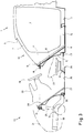
- a passenger compartment 1 which has side door openings 2 and carries a rear module (not shown) open to the front.
- the front opening is delimited by the upper windshield delimitation 3, the cowl pillars 4, the rear delimitations 5 of the front wheel cutouts and a boundary edge 6, 6 'of the floor 7 of the passenger cell 1 which projects into the passenger compartment 1 the circular arc extends from the lateral edges 8 into the base 7, as shown in FIGS. 1, 2 and 4.
- the lateral edges 8, which extend from the floor 7 to the lower corners 9 of the windshield opening 10, are preferably formed in a straight line and are covered to the outside by the side parts 11 of the passenger compartment 1.
- Both the boundary edge 6 of the base 7 and the lateral edges 8 are designed as an adhesive channel 12 (FIG.
- a front module 13 is shown in FIG. This is carried out with the inclusion of load-bearing elements 18, a pedal and steering system 19, a complete dashboard 20 with heating, ventilation and possibly air-conditioning system, a front hood 21, the headlights 22, possibly a spare wheel, the necessary insulating material and floor coverings Seats 23, the front axle system 24 with the wheel suspensions 25 and, in the case of front-wheel drive, also with the drive unit, consisting of engine and transmission, pre-assembled. In a rear-wheel drive motor vehicle, the drive unit is received by a rear module. A base part 26 is connected to the load-bearing elements 18.
- the adhesive edge 28 or bottom adhesive edge 29 is provided with centering projections 30 in a manner known per se (FIG. 8).
- the outer part of the base part 26 corresponds to the shape predetermined by the boundary edge 6 of the base 7 of the passenger compartment 1. It extends to the rear so that there is a cross member 31 space on which the front seats 23 are placed.
- the cross member 31 is provided at its outer ends with means 32 for attachment to the side members 15, specifically at the points 33.
- the adhesive edges 28 correspond in their course to the lateral edges 8 or the adhesive channel 12 of the passenger compartment 1 running along them.
- the arrangement of the bolts 16, 17 on the passenger compartment 1 corresponds to bolt receptacles 34, 35 on the front module 13.
- the boundary 27 of the bottom part 26 of the front module 13 with the bottom adhesive edge 29 is pushed into the adhesive channel 12 on the boundary edge 6 of the bottom 7 of the passenger cell 1.
- the adhesive edges 28 of the front module 13 are pushed into the adhesive channels 12 of the lateral edges 8 on the passenger compartment 1.
- the bolts 16 and 17 also fit into the bolt receptacles 34 and 35.
- FIG. 6 Another advantageous embodiment of the invention is shown in FIG. 6.
- the floor 7 of the passenger compartment 1 is accordingly provided with a trapezoidal recess, ie the boundary edge 6 'delimits the same trapezoid as is the case with the floor adhesive edge 29 of the floor part 26' of the front module 13.
- a good assembly is also ensured in such an embodiment, since the bottom adhesive edge 29 only has to be moved over a short distance in order to also completely immerse into the adhesive channel 12 on the lateral areas.
- the final non-positive connection between the passenger compartment 1 and the front module 13 takes place after the adhesive edges 28 and the floor adhesive edge 29 have been joined to the adhesive channel 12 by screwing the bolts 16 and 17 onto the bolt receptacles 34 and 35.
- the bolts 17 are in the bolt receptacle 35 easily accessible from below.
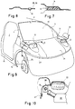
- flaps 36 are provided in the outer skin 37 of the front module 13 near the lower corners 9 of the windshield opening (FIGS. 9 and 10). These flaps 36 allow unobstructed access to the screw connection of the bolts 16 during assembly. At the same time, these flaps 36 can be used as a service opening, for example to get to the rear of the headlights 22 for replacing lamps or to fill the liquid container 38 of a windscreen washer system .
- connection along the line connections can also be made by another connection method, e.g. B. by welding, folding or the like.
- a front module for a passenger car including the front seats can also be completely pre-assembled outside the vehicle.
- a sufficiently rigid vehicle body is nevertheless achieved. The invention thus enables a considerably simpler assembly of, in particular, passenger cars compared to the previously known modular designs.
Abstract
Description
Die Erfindung betrifft ein Kraftfahrzeug in Modulbauweise, bei dem ein Frontmodul eine Fahrgastzelle nach vorn abschließt, das Frontmodul und die Fahrgastzelle punktuell kraftschlüssig miteinander verbunden sind und das Frontmodul zumindest die am vorderen Teil des Fahrzeuges untergebrachten Fahrwerks- und Bedienungsaggregate enthält.The invention relates to a motor vehicle in modular design, in which a front module closes a passenger cell to the front, the front module and the passenger cell are non-positively connected to one another and the front module contains at least the chassis and operating units housed on the front part of the vehicle.
Ein Kraftfahrzeug dieser Art ist mit GB-P 567 975 beschrieben und dargestellt. Bei diesem Kraftfahrzeug sind sowohl ein Frontmodul als auch ein Heckmodul durch ebene quer zur Fahrzeuglängsrichtung verlaufende Trennflächen von einem mittleren Fahrzeugkörper abgeteilt. Lediglich Zapfen an den Modulen und entsprechende Zapfenlöcher am mittleren Fahrzeugkörper stellen einen Formschluß zwischen diesen Sektionen her, während in der Nähe dieser Zapfen angeordnete Spannschrauben den notwendigen Kraftschluß aufbringen. Eine solche Bauweise ist nur bei Nutzkraftwagen möglich, bei denen eine komplette Fahrerhauszelle abgetrennt werden kann. Bei Personenkraftwagen, bei denen sowohl Fahrer als auch Mitfahrer in einer gemeinsamen Fahrgastzelle untergebracht sind, ist eine derartige glattflächige Teilung von Modulen nicht möglich.A motor vehicle of this type is described and shown with GB-P 567 975. In this motor vehicle, both a front module and a rear module are separated from a central vehicle body by flat dividing surfaces running transversely to the longitudinal direction of the vehicle. Only pins on the modules and corresponding pin holes on the middle vehicle body create a positive connection between these sections, while clamping screws arranged in the vicinity of these pins apply the necessary force. Such a construction is only possible with commercial vehicles in which a complete cab can be separated. In the case of passenger cars in which both driver and passenger are accommodated in a common passenger cell, such a smooth division of modules is not possible.
Mit der CH-PS 295 873 ist ein Personenkraftwagen beschrieben, welcher aus einem biege- und verdrehsteifen Wagenkasten, dem vorderen Fahrwerk, dem hinteren Fahrwerk sowie einer vorderen und einer hinteren Abschlußverkleidung besteht. Dabei soll der Wagenkasten vorn und hinten durch Endwände bzw. Öffnungen mit verstärkten Kanten begrenzt sein. Die Trennflächen können eben sein, aber auch gekrümmt bzw. geknickt sein und zwischen Wagenkasten und Fahrwerken werden Dreipunktverbindungen vorgeschlagen, die als Steck- oder Schraubverbindungen ausgeführt sind. Bei einem Kraftfahrzeug dieser Art haben die Bauteile des Wagenkastens allein alle auftretenden Kräfte zu übertragen. Die als Modul angesetzten Fahrwerke sowie die Verkleidungen nehmen daran nicht teil. Bei der punktuellen Übertragung der Kräfte von einem Modul zum anderen sind die Kräfte an den Krafteinleitungspunkten zwar genau bestimmbar, die allein kraftaufnehmenden Bauteile müssen aber entsprechend stark dimensioniert werden. Dies führt zu einem hohen Fahrzeuggewicht mit den daraus folgenden Nachteilen.With the CH-PS 295 873 a passenger car is described, which consists of a rigid and torsionally rigid body, the front chassis, the rear chassis and a front and a rear trim panel consists. The body should be limited at the front and rear by end walls or openings with reinforced edges. The separating surfaces can be flat, but can also be curved or kinked, and three-point connections are proposed between the car body and undercarriages, which are designed as plug-in or screw connections. In a motor vehicle of this type, the components of the car body alone have to transmit all the forces that occur. The running gear set as a module and the cladding do not take part in it. With the selective transfer of the forces from one module to the other, the forces at the force introduction points can be determined exactly, but the force-absorbing components alone have to be dimensioned accordingly strongly. This leads to a high vehicle weight with the resulting disadvantages.
Um auch bei Modulbauweise eine lineare Kraftübertragung realisieren zu können, ist es bekannt (DE 33 15 646), an Begrenzungslinien des einen Moduls eine U-förmige Rinne als Klebstoffträger vorzusehen, in welche Klebekanten des anderen Moduls eingelegt werden. Nach Aushärten des Klebers wird so eine lineare Kraftübertragung von einem Modul zum anderen erzielt. Damit kann bei Gewinn an Festigkeit und Steifigkeit erheblich Gewicht gespart werden. Derartige Verbindungen, die zusätzlich auch durch Schrauben punktuell gesichert sein können, sind jedoch bisher lediglich zwischen solchen Baueinheiten verwendet worden, die als funktional zusammengehörige Gruppe modular vormontiert waren, um dann als mittragendes Element in den eigentlich tragenden Fahrzeugkörper eingesetzt zu werden.In order to be able to implement a linear force transmission even in the case of a modular construction, it is known (
Aufgabe der vorliegenden Erfindung dagegen ist es, ein Kraftfahrzeug in Modulbauweise zu schaffen, dessen Frontmodul neben der Zusammenfassung der Frontaggregate auch tragende Funktionen der Fahrgastzelle übernimmt und damit bei der Funktion des Fahrzeuges die Modul-Struktur nicht mehr in Erscheinung tritt.The object of the present invention, on the other hand, is to provide a motor vehicle of modular construction, the front module of which, in addition to the combination of the front units, also carries out load-bearing functions of the passenger compartment and thus does not affect the module structure when the vehicle is functioning appears more.
Erfindungsgemäß wird diese Aufgabe dadurch gelöst, daß das Frontmodul den Bereich von Unterkante Windschutzscheibe bis in den Bereich des Bodens der Fahrgastzelle einschließlich des vorderen Bodens und der darauf befindlichen vorderen Sitze umfaßt, der Begrenzungsrand des Bodenteils des Frontmoduls sowie seitliche Ränder, die sich vom Bodenteil zum Bereich der unteren Ecken der Windschutzscheibenöffnung erstrecken, mit der Fahrgastzelle in an sich bekannter Weise mit einem entlang des Begrenzungsrandes und der seitlichen Ränder verlaufenden Steg in einen mit der Fahrgastzelle verbundenen Klebekanal eingreifen und mittels darin eingelagertem Kleber verklebt sind.According to the invention this object is achieved in that the front module comprises the area from the lower edge of the windshield to the area of the floor of the passenger compartment including the front floor and the front seats located thereon, the boundary edge of the bottom part of the front module and lateral edges which extend from the floor part to Extend the area of the lower corners of the windshield opening, engage with the passenger compartment in a manner known per se with a web running along the boundary edge and the lateral edges in an adhesive channel connected to the passenger compartment and are glued by means of adhesive embedded therein.
Der den Bodenteil umfassende Steg sowie der dazugehörige Teil des an der Fahrgastzelle befindlichen Klebekanals sind vorzugsweise in einer Ebene angeordnet und in Draufsicht kreisbogenförmig ausgeführt, wobei sich der Kreisbogen von den unteren Begrenzungen der seitlichen Ränder in den Boden der Fahrgastzelle erstreckt.The web comprising the bottom part and the associated part of the adhesive channel located on the passenger compartment are preferably arranged in one plane and are designed in the form of a circular arc in plan view, the circular arc extending from the lower boundaries of the lateral edges into the floor of the passenger compartment.
Der Bodenteil kann anstelle einer kreisbogenförmigen Draufsicht auch trapezförmig sein, wobei sich die größere Basis des Trapezes zwischen den unteren Begrenzungen der seitlichen Ränder befindet, während die kleinere Basis im Boden der Fahrgastzelle liegt und so die Seiten dieses Trapezes keilförmig in den Boden reichen.The bottom part can also be trapezoidal instead of an arc-shaped plan view, the larger base of the trapezoid being located between the lower boundaries of the side edges, while the smaller base lies in the floor of the passenger compartment, so that the sides of this trapezoid extend into the floor in a wedge shape.
Beide dieser vorzugsweise genannten Ausführungsformen ermöglichen das Einsetzen des Steges des Bodenteils in den Klebekanal des Bodens innerhalb eines kurzen Montageweges. Dadurch wird die Montage des Frontmoduls mit der Fahrgastzelle insgesamt vereinfacht und die Gefahr des Austretens von Klebstoff aus dem Klebekanal wird verringert. Ein in Draufsicht kreisbogenförmiger Steg und Klebekanal ermöglichen einen problemlosen Ausgleich von Winkeltoleranzen zwischen dem Frontmodul und der Fahrgastzelle, in dem die beiden Module innerhalb des Kreisbogens gegeneinander gedreht werden können. Damit können unabhängig von Fertigungstoleranzen beide seitlichen Ränder gleichermaßen in Eingriff mit den ihnen zugeordneten Klebekanälen gebracht werden.Both of these preferred embodiments allow the web of the base part to be inserted into the adhesive channel of the base within a short assembly path. This simplifies the assembly of the front module with the passenger compartment as a whole and reduces the risk of adhesive escaping from the adhesive duct. A bridge and adhesive channel in the form of a circular top view enable problem-free compensation of angular tolerances between the front module and the passenger compartment, in which the two modules can be rotated against each other within the circular arc. This means that both side edges can be brought into engagement with the adhesive channels assigned to them, regardless of manufacturing tolerances.
Auf dem hinteren Ende des sich in die Fahrgastzelle erstreckenden Bodenteils des Frontmoduls ist zweckmäßigerweise ein Querträger befestigt, der seitlich das Bodenteil überragt und mit den überragenden Enden an seitlichen Längsträgern der Fahrgastzelle verbunden ist.On the rear end of the floor part of the front module which extends into the passenger compartment, a cross member is expediently fastened, which projects laterally beyond the base part and is connected to the projecting ends on the side longitudinal members of the passenger compartment.
Auf diesem Querträger stützen sich vorzugsweise die vorderen Sitze ab, die somit ebenfalls zu dem Frontmodul des Kraftfahrzeuges gehören.The front seats, which thus also belong to the front module of the motor vehicle, are preferably supported on this cross member.
Erfindungsgemäß ist das Frontmodul neben seiner Klebeverbindung entlang der Begrenzungslinien am Bodenteil und an den seitlichen Rändern in an sich bekannter Weise an mehreren Punkten der Fahrgastzelle kraftschlüssig befestigt, wobei die Befestigungspunkte jeweils nahe der seitlichen Begrenzung des Bodenteils sowie nahe der unteren Ecken der Windschutzscheibenöffnung angeordnet sind.According to the invention, in addition to its adhesive connection along the boundary lines on the floor part and on the side edges, in a manner known per se, it is non-positively fastened at several points of the passenger compartment, the fastening points being arranged in each case near the side boundary of the floor part and near the lower corners of the windshield opening.
Um insbesondere die Befestigungspunkte nahe der unteren Ecken der Windschutzscheibenöffnung bei der Montage zugänglich zu machen, sind in der Außenhaut des Frontmoduls über diesen Punkten mit Klappen versehene Öffnungen vorgesehen, welche gleichzeitig als Wartungsöffnungen für darunter befindliche Aggregate, wie z. B. eine Scheibenwaschanlage, eine Klimaanlage, die Scheinwerfer oder dergleichen, dienen.In order in particular to make the fastening points near the lower corners of the windshield opening accessible during assembly, openings are provided with flaps in the outer skin of the front module above these points, which at the same time serve as maintenance openings for units located underneath, such as, for. B. a windshield washer, an air conditioner, the headlights or the like.
Ausführungsbeispiele der Erfindung sind nachstehend anhand von Zeichnungen näher beschrieben. Es zeigen:
- Fig. 1:
- eine Fahrgastzelle eines erfindungsgemäßen Kraftfahrzeuges in perspektivischer Ansicht;
- Fig. 2:
- ein Frontmodul eines erfindungsgemäßen Kraftfahrzeuges in perspektivischer Ansicht;
- Fig. 3:
- eine schematisierte Seitenansicht des Frontmoduls und der Fahrgastzelle;
- Fig. 4:
- eine schematisierte Draufsicht auf Frontmodul und Fahrgastzelle in der Anordnung gemäß
Figur 3; - Fig. 5:
- einen Schnitt entlang der Linie A - A in
Figur 4 in schematisierter Form; - Fig. 6:
- eine Draufsicht
analog Figur 4 eines anderen Ausführungsbeispiels; - Fig. 7:
- einen Schnitt entlang der Linie B - B in
Figur 4 in vergrößerter Darstellung; - Fig. 8:
- einen Schnitt entlang der Linie C - C in
Figur 4 in vergrößerter Darstellung; - Fig. 9:
- eine Teilansicht von schräg vorn auf ein erfindungsgemäßes Kraftfahrzeug;
- Fig. 10:
- den schematisierten Schnitt entlang der Linie D - D in
Figur 9.
- Fig. 1:
- a passenger compartment of a motor vehicle according to the invention in a perspective view;
- Fig. 2:
- a front module of a motor vehicle according to the invention in a perspective view;
- Fig. 3:
- a schematic side view of the front module and the passenger compartment;
- Fig. 4:
- a schematic plan view of the front module and passenger compartment in the arrangement according to Figure 3;
- Fig. 5:
- a section along the line A - A in Figure 4 in schematic form;
- Fig. 6:
- a plan view analogous to Figure 4 of another embodiment;
- Fig. 7:
- a section along the line B - B in Figure 4 in an enlarged view;
- Fig. 8:
- a section along the line C - C in Figure 4 in an enlarged view;
- Fig. 9:
- a partial view obliquely from the front of a motor vehicle according to the invention;
- Fig. 10:
- the schematic section along the line D - D in Figure 9.
Eine Fahrgastzelle 1, welche seitliche Türöffnungen 2 aufweist und ein nicht dargestelltes Heckmodul trägt, ist nach vorn offen. Die vordere Öffnung ist begrenzt von der oberen Windschutzscheibenbegrenzung 3, den Windlaufsäulen 4, den hinteren Begrenzungen 5 der vorderen Radausschnitte sowie einen in die Fahrgastzelle 1 hineinragenden Begrenzungsrand 6, 6' des Bodens 7 der Fahrgastzelle 1. Der Begrenzungsrand 6 ist vorteilhafterweise kreisbogenförmig ausgeführt, wobei sich der Kreisbogen von seitlichen Rändern 8 ausgehend in den Boden 7 erstreckt, wie dies die Figuren 1, 2 und 4 darstellen. Die seitlichen Ränder 8, die sich vom Boden 7 zu den unteren Ecken 9 der Windschutzscheibenöffnung 10 erstrecken, sind vorzugsweise geradlinig geformt und von den Seitenteilen 11 der Fahrgastzelle 1 nach außen abgedeckt. Sowohl der Begrenzungsrand 6 des Bodens 7 als auch die seitlichen Ränder 8 sind als Klebekanal 12 ausgebildet (Figur 7), der vor dem Zusammenbau der Fahrgastzelle 1 mit einem Frontmodul 13 in an sich bekannter Weise mit Kleber 14 gefüllt wird. Nahe der unteren Ecken 9 der Windschutzscheibenöffnung 10 sowie in Verlängerung von seitlichen Längsträgern 15 sind an der Fahrgastzelle 1 Bolzen 16 und 17 für eine kraftschlüssige Befestigung des Frontmoduls 13 vorgesehen.A
In Figur 2 ist ein Frontmodul 13 dargestellt. Dieses wird unter Einbeziehung von tragenden Elementen 18, einem Pedal- und Lenksystem 19, einer kompletten Armaturentafel 20 mit Heizungs-, Lüftungs- und eventuell Klimasystem, einer Fronthaube 21, den Scheinwerfern 22, eventuell einem Ersatzrad, dem erforderlichen Dämmaterial und Bodenbelägen, den vorderen Sitzen 23, dem Vorderachssystem 24 mit den Radaufhängungen 25 und, - bei Frontantrieb -, auch mit dem Antriebsaggegrat, bestehend aus Motor und Getriebe, vormontiert. Bei einem heckgetriebenen Kraftfahrzeug wird das Antriebsaggregat von einem Heckmodul aufgenommen. Mit den tragenden Elementen 18 verbunden ist ein Bodenteil 26. Beiderseits einer äußeren Begrenzung 27 des Bodenteils 26 verläuft schräg nach vorn oben bis in den Bereich der unteren Ecke 9 der Windschutzscheibenöffnung 10 eine Klebekante 28, die sich als Bodenklebekante 29 auch am gesamten nach hinten freien Bodenteil 26 fortsetzt. Die Klebekante 28 bzw. Bodenklebekante 29 ist in an sich bekannter Weise mit Zentrierwarzen 30 versehen (Figur 8). Das Bodenteil 26 entspricht in seiner äußeren Form der durch den Begrenzungsrand 6 des Bodens 7 der Fahrgastzelle 1 vorgegebenen Form. Es erstreckt sich soweit nach hinten, daß darauf ein Querträger 31 Raum findet, auf welchem die vorderen Sitze 23 aufgesetzt sind. Der Querträger 31 ist an seinen äußeren Enden mit Mitteln 32 zur Befestigung an den Längsträgern 15, und zwar an den Stellen 33, versehen. Die Klebekanten 28 entsprechen in ihrem Verlauf den seitlichen Rändern 8 bzw. dem daran entlang führenden Klebekanal 12 der Fahrgastzelle 1. Der Anordnung der Bolzen 16, 17 an der Fahrgastzelle 1 entsprechen Bolzenaufnahmen 34, 35 am Frontmodul 13.A
Werden Fahrgastzelle 1 und Frontmodul 13 zusammengefügt, dann wird die Begrenzung 27 des Bodenteils 26 des Frontmoduls 13 mit der Bodenklebekante 29 in den Klebekanal 12 am Begrenzungsrand 6 des Bodens 7 der Fahrgastzelle 1 geschoben. Gleichzeitig werden auch die Klebekanten 28 des Frontmoduls 13 in die Klebekanäle 12 der seitlichen Ränder 8 an der Fahrgastzelle 1 geschoben. Dabei fügen sich auch die Bolzen 16 und 17 in die Bolzenaufnahmen 34 und 35. Infolge der kreisbogenförmigen Begrenzung des Bodens 7 der Fahrgastzelle 1 am Begrenzungsrand 6 und damit am Klebekanal 12 sowie des Bodenteils 26 des Frontmoduls 13 entlang der Begrenzung 27 und damit der Klebekante 28 kann sich das Frontmodul 13 beim Verschrauben der Bolzen 16, 17 in den Bolzenaufnahmen 34, 35 in seiner Klebeverbindung unproblematisch ausrichten. Durch diese vorteilhafte Gestaltung gleichen sich unvermeidliche Fertigungstoleranzen aus.If
Eine andere vorteilhafte Ausführungsform der Erfindung ist in Figur 6 dargestellt. Bei dieser ist das Bodenteil 26' des Frontmoduls 13 trapezförmig ausgeführt, und zwar derart, daß die größere Basis des Trapezes unmittelbar unterhalb der Armaturentafel 20 liegt und die kleinere Basis des Trapezes im Inneren der Fahrgastzelle 1 liegt. Der Boden 7 der Fahrgastzelle 1 ist dementsprechend mit einer trapezförmigen Aussparung versehen, d. h., der Begrenzungsrand 6' umgrenzt das gleiche Trapez, wie dies von der Bodenklebekante 29 des Bodenteils 26' des Frontmoduls 13 geschieht. Auch bei einer solchen Ausführung ist eine gute Montage gewährleistet, da die Bodenklebekante 29 lediglich über eine kurze Strecke bewegt werden muß, um auch an den seitlichen Bereichen vollständig in den Klebekanal 12 einzutauchen.Another advantageous embodiment of the invention is shown in FIG. 6. This is the bottom part 26 'of the
Die endgültige kraftschlüssige Verbindung zwischen der Fahrgastzelle 1 und dem Frontmodul 13 erfolgt nach dem Fügen der Klebekanten 28 und der Bodenklebekante 29 mit dem Klebekanal 12 durch Verschrauben der Bolzen 16 und 17 an den Bolzenaufnahmen 34 und 35. Dabei sind die Bolzen 17 in der Bolzenaufnahme 35 von unten her gut erreichbar. Um auch die Bolzen 16 an der Bolzenaufnahme 34 an dem an sich sonst fertig montierten Frontmodul 13 zugänglich zu machen, sind nahe der unteren Ecken 9 der Windschutzscheibenöffnung 10 Klappen 36 in der Außenhaut 37 des Frontmoduls 13 vorgesehen (Figur 9 und 10). Diese Klappen 36 ermöglichen bei der Montage einen unbehinderten Zugriff auf die Verschraubung der Bolzen 16. Gleichzeitig können diese Klappen 36 als Serviceöffnung genutzt werden, um beispielsweise an die Rückseiten der Scheinwerfer 22 zum Auswechseln von Lampen zu gelangen oder den Flüssigkeitsbehälter 38 einer Scheibenwaschanlage auffüllen zu können.The final non-positive connection between the
Der Erfindung entspricht es natürlich auch, wenn an den Linienverbindungen zwischen Fahrgastzelle und Frontmodul anstelle der Klebekanten ein Klebekanal und somit anstelle des Klebekanals eine Klebekante vorgesehen wird.It is of course also in accordance with the invention if an adhesive channel is provided on the line connections between the passenger compartment and the front module instead of the adhesive edges and thus an adhesive edge is provided instead of the adhesive channel.
Die Verbindung entlang der Linienverbindungen kann anstelle der Klebeverbindung auch durch ein anderes Verbindungsverfahren erfolgen, z. B. durch Schweißen, Falzen oder dergleichen.The connection along the line connections can also be made by another connection method, e.g. B. by welding, folding or the like.
Bei einem Kraftfahrzeug nach der Erfindung kann ein Frontmodul auch für einen Personenkraftwagen einschließlich der vorderen Sitze komplett außerhalb des Fahrzeuges vormontiert werden. Trotzdem wird ein ausreichend steifer Fahrzeugkörper erzielt. Die Erfindung ermöglicht so eine erheblich einfachere Montage von insbesondere Personenkraftwagen gegenüber den bisher bekannten Modulbauweisen.In a motor vehicle according to the invention, a front module for a passenger car including the front seats can also be completely pre-assembled outside the vehicle. A sufficiently rigid vehicle body is nevertheless achieved. The invention thus enables a considerably simpler assembly of, in particular, passenger cars compared to the previously known modular designs.
Claims (8)
Applications Claiming Priority (2)
| Application Number | Priority Date | Filing Date | Title |
|---|---|---|---|
| DE4228120A DE4228120A1 (en) | 1992-08-25 | 1992-08-25 | Modular motor vehicle |
| DE4228120 | 1992-08-25 |
Publications (2)
| Publication Number | Publication Date |
|---|---|
| EP0584576A1 true EP0584576A1 (en) | 1994-03-02 |
| EP0584576B1 EP0584576B1 (en) | 1995-10-11 |
Family
ID=6466322
Family Applications (1)
| Application Number | Title | Priority Date | Filing Date |
|---|---|---|---|
| EP93112214A Expired - Lifetime EP0584576B1 (en) | 1992-08-25 | 1993-07-30 | Motor vehicle in modular construction |
Country Status (2)
| Country | Link |
|---|---|
| EP (1) | EP0584576B1 (en) |
| DE (2) | DE4228120A1 (en) |
Cited By (14)
| Publication number | Priority date | Publication date | Assignee | Title |
|---|---|---|---|---|
| WO1996013421A1 (en) * | 1994-10-26 | 1996-05-09 | Norbert Basler | Process for building a motor vehicle |
| EP0718175A1 (en) * | 1994-12-20 | 1996-06-26 | Robert Bosch Gmbh | Modular assembly for a motor vehicle |
| EP0752363A2 (en) * | 1995-07-03 | 1997-01-08 | Adam Opel Ag | Cover for the header box of a motor vehicle radiator |
| DE19701571A1 (en) * | 1997-01-17 | 1998-07-23 | Andreas Doernhoefer | Concept vehicle for highly variable modular car |
| DE19813548A1 (en) * | 1998-03-27 | 1999-09-30 | Opel Adam Ag | Crossbar for a motor vehicle |
| GB2378157A (en) * | 2001-08-01 | 2003-02-05 | Land Rover Uk Ltd | Vehicle construction |
| WO2004024539A1 (en) * | 2002-08-27 | 2004-03-25 | Daimlerchrysler Ag | Body comprising a support structure made of assembled partial modules |
| WO2006026942A1 (en) * | 2004-09-09 | 2006-03-16 | Wilhelm Karmann Gmbh | Module of a modularly designed motor vehicle frame |
| FR2893904A1 (en) * | 2005-11-30 | 2007-06-01 | Renault Sas | Motor vehicle`s body shell, has projection for positioning and centering shell on cradle, and bore receiving projection during reassembling of cradle, where longitudinal axis of projection is perpendicular to horizontal plane of shell |
| DE102008038747A1 (en) * | 2008-08-12 | 2010-02-25 | Bayerische Motoren Werke Aktiengesellschaft | Method for positioning and joining body parts |
| ITLU20100010A1 (en) * | 2010-08-09 | 2012-02-10 | Fabio Domenici | BODY STRUCTURE WITH REPLACEABLE MODULES |
| WO2016001612A1 (en) * | 2014-07-04 | 2016-01-07 | Renault S.A.S. | Motor vehicle comprising devices for attachment of a vehicle body on a vehicle chassis |
| WO2016192921A1 (en) * | 2015-06-03 | 2016-12-08 | Bayerische Motoren Werke Aktiengesellschaft | Group of motor vehicles |
| IT201800004711A1 (en) * | 2018-04-19 | 2018-07-19 | Vehicle chassis and module for said chassis |
Families Citing this family (10)
| Publication number | Priority date | Publication date | Assignee | Title |
|---|---|---|---|---|
| DE19606779A1 (en) * | 1996-02-23 | 1997-08-28 | Opel Adam Ag | Method for mounting and painting of vehicles with self-supporting bodies |
| DE19860794A1 (en) * | 1998-12-30 | 2000-07-06 | Volkswagen Ag | Modular motor vehicle body fabrication system uses the same driver's cabin module for all vehicle types, and small groups of different modules for front and rear bodies, screwed to cabin |
| DE29913407U1 (en) * | 1999-07-31 | 2000-12-21 | Kuka Schweissanlagen Gmbh | Tensioning device and side wall frame for a vehicle body |
| DE10018407B4 (en) * | 2000-04-13 | 2007-12-06 | Adam Opel Ag | Body of a motor vehicle with a seat module |
| DE10239992A1 (en) * | 2002-08-27 | 2004-03-18 | Daimlerchrysler Ag | Motor vehicle body has front end section of floor belonging to front end module and extends rearwards between side longitudinal support member sections over considerable length section of base module |
| DE102004035530B4 (en) * | 2004-07-22 | 2020-08-13 | Bayerische Motoren Werke Aktiengesellschaft | Vehicle body with at least one front end and one passenger cell |
| DE102005039400A1 (en) * | 2005-08-20 | 2007-02-22 | Audi Ag | Bodywork for car has fixing device carrier of smaller height than height of facing end of rear part or front part |
| DE102010045273A1 (en) | 2010-09-14 | 2012-03-15 | Detlef Alwes | Energy absorbing structure for reducing impact energy on objects, has two assemblies of object for receiving impact energy in case of collision on shear deformation elements |
| DE102011003258A1 (en) * | 2011-01-27 | 2012-08-02 | Rücker GmbH | Modular system for alternatively manufacturing electric passenger car or electric utility vehicle, has passenger car structure or lorry structure alternatively connected with single chassis or drive module by using bolts |
| US8727426B2 (en) * | 2012-03-16 | 2014-05-20 | GM Global Technology Operations LLC | Expandable vehicle system and method of expanding a vehicle |
Citations (3)
| Publication number | Priority date | Publication date | Assignee | Title |
|---|---|---|---|---|
| DE3315646A1 (en) * | 1983-04-29 | 1984-10-31 | Adam Opel AG, 6090 Rüsselsheim | PRE-ASSEMBLED UNIT FOR THE COCKPIT AREA OF MOTOR VEHICLES, ESPECIALLY PERSONAL VEHICLES, AND METHOD FOR INSTALLING SUCH A PRE-ASSEMBLED UNIT |
| FR2618746A1 (en) * | 1987-07-28 | 1989-02-03 | Peugeot | Removable motor vehicle structure and method for assembling a vehicle including such a structure |
| FR2622167A1 (en) * | 1987-10-27 | 1989-04-28 | Peugeot | Motor vehicle structure |
Family Cites Families (13)
| Publication number | Priority date | Publication date | Assignee | Title |
|---|---|---|---|---|
| FR1539047A (en) * | 1967-07-05 | 1968-09-13 | High security motor vehicle | |
| GB1237615A (en) * | 1969-08-28 | 1971-06-30 | Ford Motor Co | Motor vehicle bodies |
| DE2211976A1 (en) * | 1972-03-13 | 1973-09-27 | Daimler Benz Ag | STRUCTURAL STRUCTURE FOR A MOTOR VEHICLE, IN PARTICULAR FOR A PERSONAL CAR |
| DE2923874C2 (en) * | 1979-06-13 | 1984-01-05 | Audi Nsu Auto Union Ag, 7107 Neckarsulm | Method for producing a vehicle body and vehicle body produced according to the method |
| DE3223156A1 (en) * | 1982-06-22 | 1983-12-22 | Dr.Ing.H.C. F. Porsche Ag, 7000 Stuttgart | STRUCTURE FOR MOTOR VEHICLES, PARTICULARLY PERSONAL VEHICLES |
| DE3330140A1 (en) * | 1983-08-20 | 1985-03-07 | Adam Opel AG, 6090 Rüsselsheim | PRE-ASSEMBLED UNIT FOR THE COCKPIT AREA OF MOTOR VEHICLES, IN PARTICULAR PERSONAL VEHICLES |
| DE3702619A1 (en) * | 1987-01-29 | 1988-08-11 | Opel Adam Ag | Passenger car and method for the production of a car of this type |
| DE3809456C2 (en) * | 1987-03-27 | 1995-06-14 | Nissan Motor | Vehicle body and method of manufacturing the same |
| FR2615156B1 (en) * | 1987-05-13 | 1989-08-18 | Peugeot Aciers Et Outillage | MODULAR STRUCTURE FOR VEHICLE AND ITS APPLICATION TO THE AUTOMATIC ASSEMBLY THEREOF |
| DE3718841A1 (en) * | 1987-06-05 | 1988-12-22 | Audi Ag | Frame arrangement for motor vehicles |
| FR2621550B1 (en) * | 1987-10-07 | 1990-02-23 | Peugeot | AUTOMOTIVE VEHICLE STRUCTURE WITH MONOCOQUE BODY AND MOUNTING METHOD THEREOF |
| DE4018592A1 (en) * | 1990-06-09 | 1991-12-12 | Porsche Ag | BODY FOR A MOTOR VEHICLE, ESPECIALLY A PASSENGER VEHICLE |
| EP0512576B1 (en) * | 1991-05-10 | 1995-08-09 | Mazda Motor Corporation | Vehicle assembling method and vehicle body structure |
-
1992
- 1992-08-25 DE DE4228120A patent/DE4228120A1/en not_active Withdrawn
-
1993
- 1993-07-30 DE DE59300746T patent/DE59300746D1/en not_active Expired - Lifetime
- 1993-07-30 EP EP93112214A patent/EP0584576B1/en not_active Expired - Lifetime
Patent Citations (3)
| Publication number | Priority date | Publication date | Assignee | Title |
|---|---|---|---|---|
| DE3315646A1 (en) * | 1983-04-29 | 1984-10-31 | Adam Opel AG, 6090 Rüsselsheim | PRE-ASSEMBLED UNIT FOR THE COCKPIT AREA OF MOTOR VEHICLES, ESPECIALLY PERSONAL VEHICLES, AND METHOD FOR INSTALLING SUCH A PRE-ASSEMBLED UNIT |
| FR2618746A1 (en) * | 1987-07-28 | 1989-02-03 | Peugeot | Removable motor vehicle structure and method for assembling a vehicle including such a structure |
| FR2622167A1 (en) * | 1987-10-27 | 1989-04-28 | Peugeot | Motor vehicle structure |
Cited By (20)
| Publication number | Priority date | Publication date | Assignee | Title |
|---|---|---|---|---|
| WO1996013421A1 (en) * | 1994-10-26 | 1996-05-09 | Norbert Basler | Process for building a motor vehicle |
| AU713151B2 (en) * | 1994-10-26 | 1999-11-25 | Norbert Basler | A method of manufacturing a motor vehicle |
| EP0718175A1 (en) * | 1994-12-20 | 1996-06-26 | Robert Bosch Gmbh | Modular assembly for a motor vehicle |
| EP0752363A2 (en) * | 1995-07-03 | 1997-01-08 | Adam Opel Ag | Cover for the header box of a motor vehicle radiator |
| EP0752363A3 (en) * | 1995-07-03 | 1998-11-11 | Adam Opel Ag | Cover for the header box of a motor vehicle radiator |
| DE19701571A1 (en) * | 1997-01-17 | 1998-07-23 | Andreas Doernhoefer | Concept vehicle for highly variable modular car |
| DE19813548A1 (en) * | 1998-03-27 | 1999-09-30 | Opel Adam Ag | Crossbar for a motor vehicle |
| EP0945330A3 (en) * | 1998-03-27 | 2000-09-27 | Adam Opel Ag | Cross-beam for a motor vehicle body |
| GB2378157A (en) * | 2001-08-01 | 2003-02-05 | Land Rover Uk Ltd | Vehicle construction |
| WO2004024539A1 (en) * | 2002-08-27 | 2004-03-25 | Daimlerchrysler Ag | Body comprising a support structure made of assembled partial modules |
| WO2006026942A1 (en) * | 2004-09-09 | 2006-03-16 | Wilhelm Karmann Gmbh | Module of a modularly designed motor vehicle frame |
| FR2893904A1 (en) * | 2005-11-30 | 2007-06-01 | Renault Sas | Motor vehicle`s body shell, has projection for positioning and centering shell on cradle, and bore receiving projection during reassembling of cradle, where longitudinal axis of projection is perpendicular to horizontal plane of shell |
| DE102008038747A1 (en) * | 2008-08-12 | 2010-02-25 | Bayerische Motoren Werke Aktiengesellschaft | Method for positioning and joining body parts |
| ITLU20100010A1 (en) * | 2010-08-09 | 2012-02-10 | Fabio Domenici | BODY STRUCTURE WITH REPLACEABLE MODULES |
| WO2016001612A1 (en) * | 2014-07-04 | 2016-01-07 | Renault S.A.S. | Motor vehicle comprising devices for attachment of a vehicle body on a vehicle chassis |
| FR3024858A1 (en) * | 2014-08-18 | 2016-02-19 | Renault Sas | MOTOR VEHICLE COMPRISING DEVICES FOR FASTENING A VEHICLE BODY ON A VEHICLE CHASSIS |
| WO2016192921A1 (en) * | 2015-06-03 | 2016-12-08 | Bayerische Motoren Werke Aktiengesellschaft | Group of motor vehicles |
| CN107667054A (en) * | 2015-06-03 | 2018-02-06 | 宝马股份公司 | Motor vehicle group |
| US10363979B2 (en) | 2015-06-03 | 2019-07-30 | Bayerische Motoren Werke Aktiengesellschaft | Group of motor vehicles |
| IT201800004711A1 (en) * | 2018-04-19 | 2018-07-19 | Vehicle chassis and module for said chassis |
Also Published As
| Publication number | Publication date |
|---|---|
| DE4228120A1 (en) | 1994-03-03 |
| DE59300746D1 (en) | 1995-11-16 |
| EP0584576B1 (en) | 1995-10-11 |
Similar Documents
| Publication | Publication Date | Title |
|---|---|---|
| EP0584576B1 (en) | Motor vehicle in modular construction | |
| DE4319231C2 (en) | Motor vehicle body frame | |
| EP0124093B1 (en) | Pre-assembled modular unit for the driver's area of motor vehicles, particularly passenger cars, and method of installing such a pre-assembled modular unit | |
| DE102017010670C5 (en) | Side sill arrangement of a body of an electrically operated motor vehicle | |
| DE19730404B4 (en) | Subframe for motor vehicles | |
| EP1532040B1 (en) | Motor vehicle body comprising a support structure composed of large-size partial modules | |
| DE4330559C2 (en) | Modular motor vehicle | |
| EP0618106B1 (en) | Motor vehicle, in particular passenger car | |
| DE10060784A1 (en) | Rear module for passenger cars | |
| DE69926186T2 (en) | Floor group for motor vehicles | |
| DE102008055738A1 (en) | Module system for manufacturing body of car i.e. saloon car, has front car modules, main base modules and rear modules that are connected with each other by adapter component, and rear seat cross beam integrated into main base modules | |
| WO1999057002A1 (en) | Body structure of a motor vehicle | |
| EP0253967A1 (en) | Vehicle bumper | |
| EP0591715B1 (en) | Industrial vehicle, especially lorry with forward-mounted cab | |
| WO2022101180A1 (en) | Modular system for an energy storage device floor assembly for an electrically operatable passenger car, and method for producing such an energy storage device floor assembly | |
| EP1503930A1 (en) | Front wall module | |
| EP1619109A2 (en) | Vehicle body with a front structure and a passager compartment | |
| DE976897C (en) | Car body for cars and similar vehicles | |
| AT403465B (en) | CAB SERIES FOR FRONT HANDLEBAR LIFTS | |
| DE10332508A1 (en) | Cab for a commercial vehicle | |
| WO2022049170A1 (en) | Energy-store floor assembly for an electrically drivable passenger car | |
| EP0308574A1 (en) | Arrangement for transporting the steering and engine units of automotive front-driven special purpose motor vehicles | |
| DE102018133049B4 (en) | Side skirts for a motor vehicle | |
| EP0591727B1 (en) | Industrial vehicle, especially lorry with forward-mounted cab | |
| EP0838388B1 (en) | Body structure for a passenger vehicle |
Legal Events
| Date | Code | Title | Description |
|---|---|---|---|
| PUAI | Public reference made under article 153(3) epc to a published international application that has entered the european phase |
Free format text: ORIGINAL CODE: 0009012 |
|
| AK | Designated contracting states |
Kind code of ref document: A1 Designated state(s): DE FR GB |
|
| 17P | Request for examination filed |
Effective date: 19940423 |
|
| 17Q | First examination report despatched |
Effective date: 19941228 |
|
| GRAA | (expected) grant |
Free format text: ORIGINAL CODE: 0009210 |
|
| AK | Designated contracting states |
Kind code of ref document: B1 Designated state(s): DE FR GB |
|
| GBT | Gb: translation of ep patent filed (gb section 77(6)(a)/1977) |
Effective date: 19951016 |
|
| REF | Corresponds to: |
Ref document number: 59300746 Country of ref document: DE Date of ref document: 19951116 |
|
| ET | Fr: translation filed | ||
| PLBE | No opposition filed within time limit |
Free format text: ORIGINAL CODE: 0009261 |
|
| STAA | Information on the status of an ep patent application or granted ep patent |
Free format text: STATUS: NO OPPOSITION FILED WITHIN TIME LIMIT |
|
| 26N | No opposition filed | ||
| REG | Reference to a national code |
Ref country code: GB Ref legal event code: IF02 |
|
| REG | Reference to a national code |
Ref country code: GB Ref legal event code: 732E Free format text: REGISTERED BETWEEN 20090219 AND 20090225 |
|
| REG | Reference to a national code |
Ref country code: GB Ref legal event code: 732E Free format text: REGISTERED BETWEEN 20090305 AND 20090311 |
|
| REG | Reference to a national code |
Ref country code: GB Ref legal event code: 732E Free format text: REGISTERED BETWEEN 20091105 AND 20091111 |
|
| REG | Reference to a national code |
Ref country code: DE Ref legal event code: R081 Ref document number: 59300746 Country of ref document: DE Owner name: GM GLOBAL TECHNOLOGY OPERATIONS LLC (N. D. GES, US Free format text: FORMER OWNER: GM GLOBAL TECHNOLOGY OPERATIONS, INC., DETROIT, MICH., US Effective date: 20110323 Ref country code: DE Ref legal event code: R081 Ref document number: 59300746 Country of ref document: DE Owner name: GM GLOBAL TECHNOLOGY OPERATIONS LLC (N. D. GES, US Free format text: FORMER OWNER: GM GLOBAL TECHNOLOGY OPERATIONS, INC., DETROIT, US Effective date: 20110323 |
|
| PGFP | Annual fee paid to national office [announced via postgrant information from national office to epo] |
Ref country code: FR Payment date: 20110727 Year of fee payment: 19 |
|
| PGFP | Annual fee paid to national office [announced via postgrant information from national office to epo] |
Ref country code: DE Payment date: 20110727 Year of fee payment: 19 Ref country code: GB Payment date: 20110727 Year of fee payment: 19 |
|
| GBPC | Gb: european patent ceased through non-payment of renewal fee |
Effective date: 20120730 |
|
| REG | Reference to a national code |
Ref country code: FR Ref legal event code: ST Effective date: 20130329 |
|
| PG25 | Lapsed in a contracting state [announced via postgrant information from national office to epo] |
Ref country code: DE Free format text: LAPSE BECAUSE OF NON-PAYMENT OF DUE FEES Effective date: 20130201 Ref country code: FR Free format text: LAPSE BECAUSE OF NON-PAYMENT OF DUE FEES Effective date: 20120731 Ref country code: GB Free format text: LAPSE BECAUSE OF NON-PAYMENT OF DUE FEES Effective date: 20120730 |
|
| REG | Reference to a national code |
Ref country code: DE Ref legal event code: R119 Ref document number: 59300746 Country of ref document: DE Effective date: 20130201 |