EP1532040B1 - Motor vehicle body comprising a support structure composed of large-size partial modules - Google Patents
Motor vehicle body comprising a support structure composed of large-size partial modules Download PDFInfo
- Publication number
- EP1532040B1 EP1532040B1 EP03794855A EP03794855A EP1532040B1 EP 1532040 B1 EP1532040 B1 EP 1532040B1 EP 03794855 A EP03794855 A EP 03794855A EP 03794855 A EP03794855 A EP 03794855A EP 1532040 B1 EP1532040 B1 EP 1532040B1
- Authority
- EP
- European Patent Office
- Prior art keywords
- module
- body according
- basic module
- sections
- basic
- Prior art date
- Legal status (The legal status is an assumption and is not a legal conclusion. Google has not performed a legal analysis and makes no representation as to the accuracy of the status listed.)
- Expired - Lifetime
Links
- 239000002131 composite material Substances 0.000 description 5
- 238000010276 construction Methods 0.000 description 5
- 239000000853 adhesive Substances 0.000 description 2
- 230000001070 adhesive effect Effects 0.000 description 2
- 238000005516 engineering process Methods 0.000 description 2
- 238000004519 manufacturing process Methods 0.000 description 2
- 239000002184 metal Substances 0.000 description 2
- 238000004378 air conditioning Methods 0.000 description 1
- 230000013011 mating Effects 0.000 description 1
- 238000005058 metal casting Methods 0.000 description 1
- 230000001502 supplementing effect Effects 0.000 description 1
Images


Classifications
-
- B—PERFORMING OPERATIONS; TRANSPORTING
- B62—LAND VEHICLES FOR TRAVELLING OTHERWISE THAN ON RAILS
- B62D—MOTOR VEHICLES; TRAILERS
- B62D25/00—Superstructure or monocoque structure sub-units; Parts or details thereof not otherwise provided for
- B62D25/04—Door pillars ; windshield pillars
-
- B—PERFORMING OPERATIONS; TRANSPORTING
- B62—LAND VEHICLES FOR TRAVELLING OTHERWISE THAN ON RAILS
- B62D—MOTOR VEHICLES; TRAILERS
- B62D21/00—Understructures, i.e. chassis frame on which a vehicle body may be mounted
- B62D21/12—Understructures, i.e. chassis frame on which a vehicle body may be mounted assembled from readily detachable parts
-
- B—PERFORMING OPERATIONS; TRANSPORTING
- B62—LAND VEHICLES FOR TRAVELLING OTHERWISE THAN ON RAILS
- B62D—MOTOR VEHICLES; TRAILERS
- B62D25/00—Superstructure or monocoque structure sub-units; Parts or details thereof not otherwise provided for
- B62D25/02—Side panels
-
- B—PERFORMING OPERATIONS; TRANSPORTING
- B62—LAND VEHICLES FOR TRAVELLING OTHERWISE THAN ON RAILS
- B62D—MOTOR VEHICLES; TRAILERS
- B62D25/00—Superstructure or monocoque structure sub-units; Parts or details thereof not otherwise provided for
- B62D25/06—Fixed roofs
-
- B—PERFORMING OPERATIONS; TRANSPORTING
- B62—LAND VEHICLES FOR TRAVELLING OTHERWISE THAN ON RAILS
- B62D—MOTOR VEHICLES; TRAILERS
- B62D25/00—Superstructure or monocoque structure sub-units; Parts or details thereof not otherwise provided for
- B62D25/08—Front or rear portions
- B62D25/082—Engine compartments
-
- B—PERFORMING OPERATIONS; TRANSPORTING
- B62—LAND VEHICLES FOR TRAVELLING OTHERWISE THAN ON RAILS
- B62D—MOTOR VEHICLES; TRAILERS
- B62D25/00—Superstructure or monocoque structure sub-units; Parts or details thereof not otherwise provided for
- B62D25/20—Floors or bottom sub-units
- B62D25/2009—Floors or bottom sub-units in connection with other superstructure subunits
- B62D25/2018—Floors or bottom sub-units in connection with other superstructure subunits the subunits being front structures
-
- B—PERFORMING OPERATIONS; TRANSPORTING
- B62—LAND VEHICLES FOR TRAVELLING OTHERWISE THAN ON RAILS
- B62D—MOTOR VEHICLES; TRAILERS
- B62D25/00—Superstructure or monocoque structure sub-units; Parts or details thereof not otherwise provided for
- B62D25/20—Floors or bottom sub-units
- B62D25/2009—Floors or bottom sub-units in connection with other superstructure subunits
- B62D25/2036—Floors or bottom sub-units in connection with other superstructure subunits the subunits being side panels, sills or pillars
-
- B—PERFORMING OPERATIONS; TRANSPORTING
- B62—LAND VEHICLES FOR TRAVELLING OTHERWISE THAN ON RAILS
- B62D—MOTOR VEHICLES; TRAILERS
- B62D65/00—Designing, manufacturing, e.g. assembling, facilitating disassembly, or structurally modifying motor vehicles or trailers, not otherwise provided for
- B62D65/02—Joining sub-units or components to, or positioning sub-units or components with respect to, body shell or other sub-units or components
- B62D65/04—Joining preassembled modular units composed of sub-units performing diverse functions, e.g. engine and bonnet
Definitions
- the invention relates to a body for a motor vehicle specified in the preamble of claim 1. Art.
- a body is already out of the WO 96 13421 A as known, whose support structure is composed of two large-sized sub-modules.
- a base module forming the rear region of the support structure comprises lateral side members as well as a body floor, via which the basic module is connected to a front submodule.
- the base module is connected in the region of lateral upper roof pillars with a windshield frame, which is associated with the front module.
- the front module is thus crash-stable supported on the base module to form a front crumple zone of the motor vehicle.
- a front end region of the body floor belongs to the front end module and extends rearwardly between lateral longitudinal beam sections of the basic module over a considerable length range.
- a disadvantage of the present body is the fact that the front module is only sufficiently stable supported by the attachment of this windshield frame associated with the roof construction on the base module.
- the support structure is made as a chassis of extruded lightweight panels.
- the chassis comprises a base module with lateral side rails and with a body floor formed from lightweight panels, opposite is arranged to spring back the side rails.
- This base module is to be connected to a front module comprising a front end wall and a sloping pedal base.
- this front module includes two lightweight panels, which form the front end of the body floor with a composite chassis. The two lightweight panels extend over a considerable length range of the basic module to the rear.
- This basic module has a body floor extending between lateral side members, which is arranged so as to be recessed relative to the lateral side members or to side walls of the basic module.
- the base module is to be connected to a front module, which comprises an end region of the body floor extending rearwardly from a front end wall.
- the front wall itself is to be connected to the side walls of the basic module.
- From the FR 2 618 746 A is to take a body as known, at the base module to attach a front module.
- a front module For this purpose, two longitudinal members of the front-end module running close to the center of the vehicle in the longitudinal direction of the vehicle are inserted into corresponding receptacles on the underbody of the basic module.
- a body known whose support structure is composed of substantially four large-sized sub-modules whose support structure is composed of substantially four large-sized sub-modules.
- One of the sub-modules is designed as a laterally to front wall pillars heranvrades basic module with side rails and a body floor.
- the basic module is connected to a partial module designed as a front-end module which belongs to the front crumple zone of the motor vehicle and is supported on the basic module in a crash-stable manner is.
- a roof module or by provided at the front end of the basic module roof sections creates a stable connection of Vorbaumoduls on the base module.
- the invention has for its object to provide a bodywork for a motor vehicle, in which the frontal module is already set without roof construction in a more stable manner on the base module.
- upwardly projecting pillar portions are arranged at the front ends of the lateral side rail portions of the basic module, which are connectable to projecting at the lateral side rail portions of the front module upwardly column portions of the front boom module.
- the longitudinal beam sections of the front module and the basic module - via the associated column sections - are connected to each other in the vertical direction and there is a total of a stable angular attachment of the longitudinal beam and column sections of Vorbaumoduls and the basic module.
- the support structure for vehicles with different structure is used because the front module is already sufficiently stable without roof construction attached to the base module. This also results in a particularly good suitability of the support structure for open vehicles.
- the upwardly projecting column sections preferably extend approximately at right angles to the extension direction of the longitudinal members.
- the mutually associated, upwardly projecting column sections of the front module and the basic module can be connected to each other, for example, via each mating joining surfaces to front door pillars, so that on the one hand a particularly good connection of Vorbaumoduls results on the base module and on the other hand stiff and stable door pillars - preferably up At the height of the side wall edge of the support structure - are created. Between the door pillars preferably extends a front end wall which stiffen the door pillars in the vehicle transverse direction.
- connection between the front module and the base module is particularly stable when the mutually associated lateral side rail sections of the front module and the basic module are connected to each other via joining surfaces which extend over the at least approximately entire overlap length of the mutually associated side rail sections or the two modules.
- the lateral side rail portions of the front end module and the base module each have a box section closed in cross-section. After joining the mutually associated longitudinal beam sections thus lateral side members are created with a double box profile in cross-section, which are particularly stiff.
- the upwardly projecting column sections of the front module and the basic module preferably each comprise a box section closed in cross-section, so that particularly rigid door pillars are created with double cross-section box profile after joining the mutually laterally associated column sections.
- the support structure After assembly of the large-sized sub-modules, the support structure is to be clad with constraintsbeplankungs negligence, which hide the joints of the sub-modules with the specificallybeplankungs negligence. This ensures that the sub-modules on the one hand with sufficient tolerances manufacturing technology can be easily and thus inexpensively joined and on the other hand Covering the joints with a high quality impression is created.
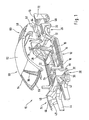
- FIG. 1 shows in a perspective exploded view a support structure 10 of a motor vehicle body, which is composed of a plurality of large-format sub-modules, which will be described in more detail below.
- the submodules of the support structure 10 are each made in the embodiment shown here from a plurality of assembled sheet metal parts; However, the sub-modules can also be prefabricated in other constructions, for example as so-called. Spaceframe, as plastic parts, metal castings, as components in so-called. Sandwich construction or the like.
- combinations of different designs for the assembled sub-modules depending on the application and load are conceivable.
- the individual modules are assembled in particular via adhesive bonds, welded joints or the like. Likewise, other common connections such as screw or the like. Imagine.
- a base module 12 of the support structure 10, which can be seen in conjunction with FIG. 1, comprises essentially a body floor 14, which is delimited laterally by longitudinal members 15.
- the basic module 12 extends with longitudinal beam sections 16 to column sections 18 of front wall columns 20, which project from the respective associated front ends of the side longitudinal beam sections 16 upwards.
- the body floor 14 of the base module 12 terminates at a considerable distance behind the front end of the base module 12 and behind the column sections 18 of the front wall pillars 20.
- the body floor 14 is here provided with a center tunnel 22 and extending outwardly therefrom cross members 24, which are firmly connected to the longitudinal members 15.
- the basic module 12 ends behind rear wheel arches 26, on the inside of which extensions 28 of the lateral side members 15 extend.
- the body floor 14 terminates at the rear on a cross member 32 which extends between the extensions 28 of the lateral side members 15 at the level of the rear wheel arches 26 in the vehicle transverse direction.
- the basic module 12 is equipped as far as possible prior to assembly with the other sub-modules.
- the interior trim, possibly the seat, the electrical and electronic equipment, or the underfloor system for example, with parts of the exhaust system already attached to the base module and possibly with adapters, connectors or the like. Provided that allow connection with other components.
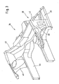
- Vorbaumodul 34 is connected, which belongs to the front crumple zone of the motor vehicle and crash-stable on the base module 12 is supported.
- the front module 34 comprises a front end region 36 of the body floor 14, which extends between lateral side member sections 38 of the front module 34.
- the front end region 36 of the body floor 14 and the lateral side rail sections 38 end toward the rear at least approximately at a height.
- the end wall 40 is bounded by column sections 42 of the front wall columns 20, which project upwards from the lateral side member sections 38 of the front module 34.
- front longitudinal members 44 and front side wall portions 46 can be seen, between which parts 48 of the wheel arch lining of the front wheel arches are arranged.
- the front module 34 is adjoined by a front module 35, which is partially shown in FIG.
- This front module 35 includes, for example the front bumper, the front end of the motor vehicle, the headlights, parts of the radiator and parts of the wheel arch trim.
- the front module 34 is also equipped as far as possible before assembly with the other submodules. In particular, not shown components and units such as the dashboard, the air conditioning, the pedal system, etc. may already be attached to the front module.
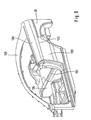
- a roof module 50 which can be seen in conjunction with FIG. 9 can be placed on the basic module 12 and the front module 34, which lateral lateral A columns 54, lateral roof columns 56, and C columns 58 in the region of the roof 52.
- the lower ends of the A-pillars 54 and the C-pillars 58 are connected to one another via a respective cross-member element 60.
- the A-pillars 54 are based on composite support structure 10 both on the base module 12 and on the front module 34 from. In other words, the A-pillars 54 are supported with their lower ends on both the upstanding column sections 18 and 42 of the base module 12 and the front module 34, which form the respective front wall pillar 20.
- Rear joining surfaces 62 of the lower ends of the C-pillars 58 are attached with joining surfaces 64 at the respectively associated upper end of the wall portions 30, for example by means of an adhesive bond.
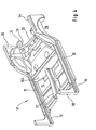
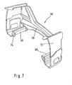
- the base module 12 is adjoined by a rear module 66, which can be seen together with FIG. 7, which belongs to the rear crumple zone of the motor vehicle together with the rear end region of the base module 12 and essentially lateral rear side rail sections 68, one of the side rail sections 68 connecting rear cross member 70 and rear side wall portions 72 includes.
- a rear module 66 which can be seen together with FIG. 7, which belongs to the rear crumple zone of the motor vehicle together with the rear end region of the base module 12 and essentially lateral rear side rail sections 68, one of the side rail sections 68 connecting rear cross member 70 and rear side wall portions 72 includes.
- the cross member 32 and the longitudinal beam extensions 28 of the base module 12 and by the side rail portions 68 and the rear cross member 70 of the rear module 66 is formed in composite support structure, a support frame, within which a spare wheel well, not shown attachable. It can be seen that the rear module 66 is connected to the base module 12 and the roof module 50 along a vertically extending vehicle transverse plane.
- a respective associated B-pillar 78 is fastened between the lateral roof pillar 56 of the roof module 50 and the lateral side member 15 of the basic module 12.
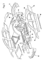
- FIG. 2 shows, in a further perspective exploded view, the support structure 10 composed of the submodules 12, 34, 50 and 66, which is clad with exterior paneling parts made of plastic, sheet metal or the like.
- front fender panels 80 are formed so that the joint 81 is covered between the upwardly projecting column sections 18 and 42 of the base module 12 and the Vorbaumoduls 34 and is not visible from the outside.
- attachment points of the A-pillars 54 of the roof module 50 to the base module 12 and the front module 34 are also covered by the front fender panels 80 and not visible.
- Lateral sill panels 82 are formed so that the joint 83 between the respective side rail portions 16 of the base module 12 and the longitudinal beam portions 38 of the front module 34 is not concealed from the outside visible.
- Rear fender panels 84 are also formed so that the joint 62,64 between the C-pillar 58 and the rear wall portion 30 is also not visible from the outside laminated. It can be seen that thus all joints of the large-sized sub-modules 12,34,50 and 66 covered with the trim parts 80,82,84 and are not visible from the outside. This ensures that the sub-modules with sufficient tolerances manufacturing technology can be easily and thus inexpensively joined and on the other hand, the cover of the joints a high quality impression is conveyed.
- the A-pillars 54, the side roof pillars 56 and the C-pillars 58 are lined with pillar trim parts 86, 88.
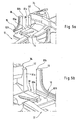
- FIGS. 5a and 5b show, in partial perspective views, the assembly of the basic module 12 and the front module 34
- FIG. 6 shows in perspective view the basic module 12 and the front module 34 after assembly.
- the front end region 36 of the body floor 14 belonging to the front module 34 extends rearwardly between the lateral side rail sections 16 over a considerable length of the base module 12.
- the mutually associated lateral side member sections 16, 38 of the front module 34 and of the base module 12 have matching joining surfaces 83 a, b at the respective joint 83 (FIG. 2), which extend over the at least approximately entire overlap length of the mutually associated side member sections 16,38 extend.
- the length of the joining surfaces 83a, b corresponds approximately to the length of the adjacent front end region 36 of the body floor 14.
- the lateral side rail sections 16, 38 of the front module 34 and the base module 12 each have a box profile closed in cross-section, so that after the assembly of each other associated side rail sections 16,38 lateral side members in the Cross-section double, about 8-shaped box profile arise.
- the box profile of the lateral longitudinal beam sections 16,38 of the front module 34 and the base module 12 each has a variable over its length, here stepped cross-section.
- the longitudinal beam sections 16, 38 are each designed as a partial shell, which are then connected to form a carrier.
- the upwardly projecting column sections 18, 42 of the basic module 12 and the front module 34 each comprise mutually adapted joining surfaces 81 a, b at the respective joint 81 (FIG. 2), via which the column sections 18, 42 are connected to the front wall pillar 20.
- the upwardly projecting column sections 18, 42 each comprise a box profile closed in cross-section, so that after assembly of the respectively associated column sections 18, 42, particularly rigid door pillars 20 having a cross-sectionally double, approximately 8-shaped box profile are created.
- the joining surfaces 81a, b of the column sections 18, 42 and the joining surfaces 83a, b of the side member sections 16, 38 run here at least approximately at right angles to one another.
- the position of the basic module 12 and the front end module 34 is thus determined in the vehicle longitudinal direction and in the vehicle vertical direction by the joining surfaces 83a, b and 81a, b.
- the position of the base module 12 and the front module 34 is not determined by the joining surfaces 83a, b and 81a, b, but for example by contact surfaces of the base module 12 and the Vorbaumoduls 34 in the region of the center tunnel 22.
- the center tunnel 22 is formed both in the front end portion 36 as well as in the body floor 14 and provided with joining surfaces.
- FIG. 9 is a fragmentary perspective view of the assembled support structure 10, which includes a left and a right side wall module 100 extending from behind the front side doors to the rear door pillars.
- the side wall module 100 is fastened to the base module 12 above the associated longitudinal member 15 and opposite the rear side wall 30.
- the side wall module 100 is supported in the vehicle transverse direction with a support assembly 102 relative to a cross member 104.
- the base module 12 and the side wall module 100 terminate at the level of a common joining surface 106, on which a coupé roof module 50 'different in this respect is fastened with a side wall region 108.
Landscapes
- Engineering & Computer Science (AREA)
- Chemical & Material Sciences (AREA)
- Combustion & Propulsion (AREA)
- Transportation (AREA)
- Mechanical Engineering (AREA)
- Manufacturing & Machinery (AREA)
- Body Structure For Vehicles (AREA)
Description
Die Erfindung betrifft eine Karosserie für einen Kraftwagen der im Oberbegriff des Patentanspruchs 1 angegebenen Art.The invention relates to a body for a motor vehicle specified in the preamble of claim 1. Art.
Eine derartige Karosserie ist bereits aus der
Als nachteilig bei der vorliegenden Karosserie ist der Umstand anzusehen, dass das Vorbaumodul erst durch die Befestigung des diesem zugeordneten Windschutzscheibenrahmens an der Dachkonstruktion hinreichend stabil an dem Grundmodul abgestützt ist.A disadvantage of the present body is the fact that the front module is only sufficiently stable supported by the attachment of this windshield frame associated with the roof construction on the base module.
Eine weitere Karosserie ist aus der
Weiter ist aus der
Aus der
Schließlich ist aus der
Der Erfindung liegt die Aufgabe zugrunde, eine Karosserie für einen Kraftwagen zu schaffen, bei der das Vorbaumodul bereits ohne Dachkonstruktion auf stabilere Weise am Grundmodul festgelegt ist.The invention has for its object to provide a bodywork for a motor vehicle, in which the frontal module is already set without roof construction in a more stable manner on the base module.
Die erfindungsgemäße Lösung dieser Aufgabe ergibt sich aus den Merkmalen des Hauptanspruchs. Vorteilhafte Ausgestaltungen der Erfindung sind den übrigen Ansprüchen zu entnehmen.The inventive solution to this problem arises from the features of the main claim. Advantageous embodiments of the invention are apparent from the remaining claims.
Bei der Tragstruktur der erfindungsgemäßen Karosserie sind an den vorderen Enden der seitlichen Längsträgerabschnitte des Grundmoduls nach oben abragende Säulenabschnitte angeordnet, welche mit an den seitlichen Längsträgerabschnitten des Vorbaumoduls nach oben abragenden Säulenabschnitten des Vorbaumoduls verbindbar sind. Hierdurch können die Längsträgerabschnitte des Vorbaumoduls und das Grundmoduls - über die zugehörigen Säulenabschnitte - auch in Höhenrichtung miteinander verbunden werden und es ergibt sich insgesamt eine stabile winklige Befestigung der Längsträger- und Säulenabschnitte des Vorbaumoduls und des Grundmoduls. Durch die sehr stabile Befestigung des Vorbaumoduls an dem Grundmodul ist die Tragstruktur für Fahrzeuge mit unterschiedlichem Aufbau verwendbar, da das Vorbaumodul bereits ohne Dachkonstruktion hinreichend stabil am Grundmodul befestigt ist. Hierdurch ergibt sich auch eine besonders gute Eignung der Tragstruktur für offene Kraftwagen. Dabei erstrecken sich die nach oben abragenden Säulenabschnitte bevorzugt etwa rechtwinklig zu der Erstreckungsrichtung der Längsträger.In the support structure of the body according to the invention upwardly projecting pillar portions are arranged at the front ends of the lateral side rail portions of the basic module, which are connectable to projecting at the lateral side rail portions of the front module upwardly column portions of the front boom module. As a result, the longitudinal beam sections of the front module and the basic module - via the associated column sections - are connected to each other in the vertical direction and there is a total of a stable angular attachment of the longitudinal beam and column sections of Vorbaumoduls and the basic module. Due to the very stable attachment of the front module to the base module, the support structure for vehicles with different structure is used because the front module is already sufficiently stable without roof construction attached to the base module. This also results in a particularly good suitability of the support structure for open vehicles. In this case, the upwardly projecting column sections preferably extend approximately at right angles to the extension direction of the longitudinal members.
Die einander zugeordneten, nach oben abragenden Säulenabschnitte des Vorbaumoduls und des Grundmoduls können beispielsweise über jeweils aneinander angepasste Fügeflächen miteinander zu vorderen Türsäulen verbunden werden, so dass sich einerseits eine besonders gute Anbindung des Vorbaumoduls an dem Grundmodul ergibt und andererseits steife und stabile Türsäulen - vorzugsweise bis auf Höhe der Bordwandkante der Tragstruktur - geschaffen sind. Zwischen den Türsäulen erstreckt sich bevorzugt eine vordere Stirnwand, welche die Türsäulen in Fahrzeugquerrichtung aussteift.The mutually associated, upwardly projecting column sections of the front module and the basic module can be connected to each other, for example, via each mating joining surfaces to front door pillars, so that on the one hand a particularly good connection of Vorbaumoduls results on the base module and on the other hand stiff and stable door pillars - preferably up At the height of the side wall edge of the support structure - are created. Between the door pillars preferably extends a front end wall which stiffen the door pillars in the vehicle transverse direction.
Die Verbindung zwischen Vorbaumodul und Grundmodul ist dabei besonders stabil, wenn die einander zugeordneten seitlichen Längsträgerabschnitte des Vorbaumoduls und des Grundmoduls über Fügeflächen miteinander verbunden sind, welche sich über die zumindest annähernd gesamte Überdeckungslänge der einander zugeordneten Längsträgerabschnitte bzw. der beiden Module erstrecken.The connection between the front module and the base module is particularly stable when the mutually associated lateral side rail sections of the front module and the basic module are connected to each other via joining surfaces which extend over the at least approximately entire overlap length of the mutually associated side rail sections or the two modules.
Zur Stabilität der Anbindung des Vorbaumoduls am Grundmodul trägt weiter bei, dass die seitlichen Längsträgerabschnitte des Vorbaumoduls und des Grundmoduls jeweils ein im Querschnitt geschlossenes Kastenprofil aufweisen. Nach dem Zusammenfügen der einander jeweils zugeordneten Längsträgerabschnitte sind somit seitliche Längsträger mit im Querschnitt doppeltem Kastenprofil geschaffen, welche besonders steif sind.For the stability of the connection of the front module on the base module further contributes that the lateral side rail portions of the front end module and the base module each have a box section closed in cross-section. After joining the mutually associated longitudinal beam sections thus lateral side members are created with a double box profile in cross-section, which are particularly stiff.
Die nach oben abragenden Säulenabschnitte des Vorbaumoduls und des Grundmoduls umfassen bevorzugt jeweils ein im Querschnitt geschlossenes Kastenprofil, so dass nach dem Zusammenfügen der einander jeweils seitlich zugeordneten Säulenabschnitte besonders steife Türsäulen mit im Querschnitt doppeltem Kastenprofil geschaffen sind.The upwardly projecting column sections of the front module and the basic module preferably each comprise a box section closed in cross-section, so that particularly rigid door pillars are created with double cross-section box profile after joining the mutually laterally associated column sections.
Nach dem Zusammenbau der großformatigen Teilmodule ist die Tragstruktur mit Außenbeplankungsteilen zu verkleiden, welche die Fügestellen der Teilmodule mit den Außenbeplankungsteilen kaschieren. Hierdurch ist gewährleistet, dass die Teilmodule einerseits mit hinreichenden Toleranzen fertigungstechnisch einfach und somit kostengünstig gefügt werden können und andererseits eine Abdeckung der Fügestellen mit einem hochwertigen Qualitätseindruck entsteht.After assembly of the large-sized sub-modules, the support structure is to be clad with Außenbeplankungsteilen, which hide the joints of the sub-modules with the Außenbeplankungsteilen. This ensures that the sub-modules on the one hand with sufficient tolerances manufacturing technology can be easily and thus inexpensively joined and on the other hand Covering the joints with a high quality impression is created.
Weitere Vorteile, Merkmale und Einzelheiten der Erfindung ergeben sich aus der nachfolgenden Beschreibung eines bevorzugten Ausführungsbeispieles sowie anhand der Zeichnungen; diese zeigen in
- Fig.1
- eine perspektivische Explosionsdarstellung auf die aus großformatigen Teilmodulen zusammengesetzte Tragstruktur der erfindungsgemäßen Kraftwagenkarosserie;
- Fig.2
- eine weitere perspektivische Explosionsdarstellung auf die aus Teilmodulen zusammengesetzte Tragstruktur, welche mit Außenbeplankungsteilen verkleidet ist;
- Fig.3
- eine Perspektivansicht auf ein als Vorbaumodul ausgebildetes Teilmodul der Tragstruktur;
- Fig.4
- eine Perspektivansicht auf ein als Grundmodul ausgebildetes Teilmodul der Tragstruktur;
- Fig.5a,b
- jeweils ausschnittsweise Perspektivansichten auf das Grundmodul und das Vorbaumodul vor dem Zusammenfügen;
- Fig.6
- eine Perspektivansicht auf das Grundmodul und das Vorbaumodul nach dem Zusammenfügen;
- Fig.7
- eine Perspektivansicht auf ein als Heckmodul ausgebildetes Teilmodul der Tragstruktur;
- Fig.8
- eine Perspektivansicht auf ein als Dachmodul ausgebildetes Teilmodul der Tragstruktur; und in
- Fig.9
- eine ausschnittsweise Perspektivansicht auf die zusammengesetzte Tragstruktur, welche jeweils ein linkes und rechtes Seitenwandmodul umfasst.
- Fig.1
- an exploded perspective view of the assembled from large-sized sub-modules support structure of the motor vehicle body according to the invention;
- Fig.2
- a further perspective exploded view of the assembled from sub-modules support structure, which is covered with Außenbeplankungsteilen;
- Figure 3
- a perspective view of a submodule designed as a front module of the support structure;
- Figure 4
- a perspective view of a designed as a basic module submodule of the support structure;
- 5a, b
- each partial perspective views of the base module and the front module before joining;
- Figure 6
- a perspective view of the base module and the front end module after assembly;
- Figure 7
- a perspective view of a formed as a rear module submodule of the support structure;
- Figure 8
- a perspective view of a formed as a roof module submodule of the support structure; and in
- Figure 9
- a fragmentary perspective view of the composite support structure, each comprising a left and right side wall module.
In Fig.1 ist in einer perspektivischen Explosionsdarstellung eine Tragstruktur 10 einer Kraftwagenkarosserie gezeigt, die aus mehreren großformatigen, im weiteren noch näher beschriebenen Teilmodulen zusammengesetzt ist. Die Teilmodule der Tragstruktur 10 sind in dem hier gezeigten Ausführungsbeispiel jeweils aus einer Mehrzahl von zusammengefügten Blechteilen hergestellt; gleichfalls können die Teilmodule jedoch auch in anderen Bauweisen, beispielsweise als sog. Spaceframe, als Kunststoffteile, Metallgussteile, als Bauteile in sog. Sandwich-Bauweise oder dgl. vorgefertigt sein. Insbesondere sind dabei auch Kombinationen unterschiedlicher Bauweisen für die zusammengefügten Teilmodule je nach Anwendung und Belastung denkbar. Die einzelnen Module sind insbesondere über Klebverbindungen, Schweißverbindungen oder dgl. zusammengefügt. Gleichfalls sind andere gängig Verbindungen wie Schraubverbindungen oder dgl. denkbar.1 shows in a perspective exploded view a
Ein in Zusammenschau von Fig.1 mit Fig.4 erkennbares Grundmodul 12 der Tragstruktur 10 umfasst im wesentlichen einen Karosserieboden 14, der seitlich von Längsträgern 15 begrenzt ist. Nach vorne reicht das Grundmodul 12 mit Längsträgerabschnitten 16 bis an Säulenabschnitte 18 von Vorderwandsäulen 20, welche von den jeweils zugeordneten vorderen Enden der seitlichen Längsträgerabschnitte 16 nach oben abragen. Der Karosserieboden 14 des Grundmoduls 12 endet in einem erheblichen Abstand hinter dem vorderen Ende des Grundmoduls 12 bzw. hinter den Säulenabschnitten 18 der Vorderwandsäulen 20. Dabei ist der Karosserieboden 14 hier mit einem Mitteltunnel 22 sowie mit von diesem sich nach außen erstreckenden Querträgern 24 versehen, welche mit den Längsträgern 15 fest verbunden sind. Hinten endet das Grundmodul 12 hinter hinteren Radhäusern 26, an deren Innenseite sich Verlängerungen 28 der seitlichen Längsträger 15 erstrecken. Oberhalb der hinteren Radhäuser 26 sind Wandbereiche 30 der jeweiligen hinteren Seitenwand angeordnet. Der Karosserieboden 14 endet hinten an einem Querträger 32, welcher sich zwischen den Verlängerungen 28 der seitlichen Längsträger 15 auf Höhe der hinteren Radhäusern 26 in Fahrzeugquerrichtung erstreckt. Das Grundmodul 12 wird bereits vor dem Zusammenfügen mit den anderen Teilmodulen so weit als möglich ausgestattet. So sind beispielsweise die Innenverkleidung, eventuell die Sitzanlage, die elektrische und elektronische Einrichtung, oder die Unterfluranlage z.B. mit Teilen der Auspuffanlage bereits an dem Grundmodul angebracht und ggf. mit Adaptern, Steckverbindungen oder dgl. versehen, die eine Verbindung mit weiteren Bauteilen ermöglichen.A
Mit dem Grundmodul 12 ist ein in Zusammenschau mit Fig.3 erkennbares Vorbaumodul 34 verbunden, welches zur vorderen Knautschzone des Kraftwagens gehört und crashstabil am Grundmodul 12 abgestützt ist. Hierzu umfasst das Vorbaumodul 34 einen vorderen Endbereich 36 des Karosseriebodens 14, welcher sich zwischen seitlichen Längsträgerabschnitten 38 des Vorbaumoduls 34 erstreckt. Wie in Zusammenschau mit den Figuren 3, 5a und 5b erkennbar, enden der vordere Endbereich 36 des Karosseriebodens 14 und die seitlichen Längsträgerabschnitte 38 nach hinten zumindest annähernd auf einer Höhe. Nach vorne endet der vordere Endbereich 36 des Karosseriebodens 14 an einer vorderen Stirnwand 40 der Fahrgastzelle, welche sich vom vorderen Endbereich 36 des Karosseriebodens 14 bis etwa auf Höhe der Bordwandkante der Tragstruktur 10 erstreckt. Seitlich wird die Stirnwand 40 von Säulenabschnitten 42 der Vorderwandsäulen 20 begrenzt, welche von den seitlichen Längsträgerabschnitten 38 des Vorbaumoduls 34 nach oben abragen. Am vorderen Ende des Vorbaumoduls 34 sind vordere Längsträger 44 sowie vordere Seitenwandbereiche 46 erkennbar, zwischen denen Teile 48 der Radhausverkleidung der vorderen Radhäuser angeordnet sind. Nach vorne schließt sich an das Vorbaumodul 34 ein Frontmodul 35 an, welches in Fig.2 teilweise dargestellt ist. Dieses Frontmodul 35 umfasst beispielsweise den vorderen Stoßfänger, den Bugbereich des Kraftwagens, die Scheinwerfer, Teile des Kühlers sowie Teile der Radhausverkleidung. Wie das Grundmodul 12 wird auch das Vorbaumodul 34 bereits vor dem Zusammenfügen mit den anderen Teilmodulen so weit als möglich ausgestattet. So können insbesondere nicht gezeigte Bauteile und Aggregate wie die Instrumententafel, die Klimaanlage, die Pedalanlage usw. bereits am Vorbaumodul angebracht sein.With the basic module 12 a recognizable in conjunction with Figure 3
Auf das Grundmodul 12 und das Vorbaumodul 34 ist ein in Zusammenschau mit Fig.9 erkennbares Dachmodul 50 aufsetzbar, welches hier seitliche A-Säulen 54, im Bereich des Dachs 52 seitliche Dachsäulen 56, und C-Säulen 58 umfasst. Die unteren Enden der A-Säulen 54 bzw. der C-Säulen 58 sind über jeweils ein Querträgerelement 60 miteinander verbunden. Die A-Säulen 54 stützen sich bei zusammengesetzter Tragstruktur 10 sowohl an dem Grundmodul 12 als auch am Vorbaumodul 34 ab. Mit anderen Worten sind die A-Säulen 54 mit ihren unteren Enden sowohl an den nach oben ragenden Säulenabschnitten 18 und 42 des Grundmoduls 12 und des Vorbaumoduls 34, welche die jeweilige Vorderwandsäule 20 bilden, abgestützt. Hinten sind Fügeflächen 62 der unteren Enden der C-Säulen 58 mit Fügeflächen 64 am jeweils zugeordneten oberen Ende der Wandbereiche 30 beispielsweise mittels einer Klebeverbindung befestigt.A
Hinten schließt sich an das Grundmodul 12 ein unter Zusammenschau mit Fig.7 erkennbares Heckmodul 66 an, welches bei zusammengesetzter Tragstruktur 10 zusammen mit dem hinteren Endbereich des Grundmoduls 12 zur hinteren Knautschzone des Kraftwagens gehört und im wesentlichen seitliche hintere Längsträgerabschnitte 68, einen die Längsträgerabschnitte 68 verbindenden hinteren Querträger 70 sowie hintere Seitenwandbereiche 72 umfasst. Durch den Querträger 32 und die Längsträgerverlängerungen 28 des Grundmoduls 12 sowie durch die Längsträgerabschnitte 68 und den hinteren Querträger 70 des Heckmoduls 66 ist bei zusammengesetzter Tragstruktur ein Tragrahmen gebildet, innerhalb dem eine nicht gezeigte Reserveradmulde anbringbar ist. Es ist ersichtlich, dass das Heckmodul 66 entlang einer vertikal verlaufenden Fahrzeugquerebene mit dem Grundmodul 12 und dem Dachmodul 50 verbunden ist. Die Befestigung des Heckmoduls 66 an dem Grundmodul 12 und dem Dachmodul 50 erfolgt über Flansche 74 an den Längsträgerverlängerungen 28 bzw. den zugeordneten Längsträgerabschnitten 68, sowie über weitere nicht gezeigte Fügestellen zwischen den Modulen 12,50 und 66. Nach hinten schließt sich an das Heckmodul 66 ein Heckendmodul 76 an, welches in Fig.2 teilweise erkennbar ist. Dieses Heckendmodul 76 umfasst beispielsweise den hinteren Stoßfänger oder die rückwärtige Beleuchtung des Kraftwagens. Es ist als selbstverständlich anzusehen, dass sowohl das Dachmodul 50 wie auch das Heckmodul 66 bereits vor dem Zusammenfügen der Tragstruktur 10 so weit als möglich mit Verkleidungen, Aggregaten und Bauteilen ausgestattet sein können.At the rear, the
Bei dem hier gezeigten fünftürigen Kraftwagen ist zwischen der seitlichen Dachsäule 56 des Dachmoduls 50 und dem seitlichen Längsträger 15 des Grundmoduls 12 eine jeweils zugeordnete B-Säule 78 befestigt.In the five-door motor vehicle shown here, a respective associated B-
In Fig.2 ist in einer weiteren perspektivischen Explosionsdarstellung die aus den Teilmodulen 12,34,50 und 66 zusammengesetzte Tragstruktur 10 dargestellt, welche mit Außenbeplankungsteilen aus Kunststoff, Blech oder dgl. verkleidet ist. So sind insbesondere vordere Kotflügelverkleidungen 80 so ausgebildet, dass die Fügestelle 81 zwischen den nach oben ragenden Säulenabschnitten 18 und 42 des Grundmoduls 12 und des Vorbaumoduls 34 abgedeckt und von außen nicht sichtbar ist. Außerdem sind durch die vordere Kotflügelverkleidungen 80 auch die Befestigungsstellen der A-Säulen 54 des Dachmoduls 50 an dem Grundmodul 12 und dem Vorbaumodul 34 ebenfalls überdeckt und nicht sichtbar. Seitliche Schwellerverkleidungen 82 sind so ausgebildet, dass die Fügestelle 83 zwischen den jeweiligen Längsträgerabschnitten 16 des Grundmoduls 12 und den Längsträgerabschnitten 38 des Vorbaumoduls 34 von außen nicht sichtbar kaschiert ist. Hintere Kotflügelverkleidungen 84 sind ebenfalls so ausgebildet, dass die Fügestelle 62,64 zwischen der C-Säule 58 und dem hinteren Wandbereich 30 ebenfalls von außen nicht erkennbar kaschiert ist. Es ist ersichtlich, dass somit alle Fügestellen der großformatigen Teilmodule 12,34,50 und 66 mit den Verkleidungsteilen 80,82,84 überdeckt und von außen nicht sichtbar sind. Hierdurch ist gewährleistet, dass die Teilmodule mit hinreichenden- Toleranzen fertigungstechnisch einfach und somit kostengünstig gefügt werden können und andererseits durch die Abdeckung der Fügestellen ein hochwertiger Qualitätseindruck vermittelt wird.FIG. 2 shows, in a further perspective exploded view, the
Die A-Säulen 54, die seitlichen Dachsäulen 56 und die C-Säulen 58 sind mit Säulenverkleidungsteilen 86,88 verkleidet.The A-pillars 54, the
In den Figuren 5a und 5b ist in ausschnittsweiser Perspektivansichten das Zusammenfügen des Grundmoduls 12 und des Vorbaumoduls 34, und in Fig.6 ist in Perspektivansicht das Grundmodul 12 und das Vorbaumodul 34 nach dem Zusammenfügen dargestellt. Es ist erkennbar, dass sich der zum Vorbaumodul 34 gehörende vordere Endbereich 36 des Karosseriebodens 14 zwischen den seitlichen Längsträgerabschnitten 16 über einen erheblichen Längenbereich des Grundmoduls 12 nach hinten erstreckt. Weiter ist erkennbar, dass die einander zugeordneten seitlichen Längsträgerabschnitte 16,38 des Vorbaumoduls 34 und des Grundmoduls 12 aneinander angepasste Fügeflächen 83a,b an der jeweiligen Fügestelle 83 (Fig.2) aufweisen, welche sich über die zumindest annähernd gesamte Überdeckungslänge der einander zugeordneten Längsträgerabschnitte 16,38 erstrecken. Dabei entspricht die Länge der Fügeflächen 83a,b etwa der Länge des angrenzenden vorderen Endbereichs 36 des Karosseriebodens 14. Die seitlichen Längsträgerabschnitte 16,38 des Vorbaumoduls 34 und des Grundmoduls 12 haben jeweils ein im Querschnitt geschlossenes Kastenprofil, so dass nach dem Zusammenfügen der einander jeweils zugeordneten Längsträgerabschnitte 16,38 seitliche Längsträger mit im Querschnitt doppeltem, etwa 8-förmigen Kastenprofil entstehen. Das Kastenprofil der seitlichen Längsträgeräbschnitte 16,38 des Vorbaumoduls 34 und des Grundmoduls 12 hat jeweils einen über seine Länge veränderlichen, hier gestuften Querschnitt. Natürlich wäre es in diesem Zusammenhang auch denkbar, dass die Längsträgerabschnitte 16,38 jeweils als Teilschale ausgebildet sind, welche dann zu einem Träger miteinander verbunden werden.FIGS. 5a and 5b show, in partial perspective views, the assembly of the
Die nach oben abragenden Säulenabschnitte 18,42 des Grundmoduls 12 und des Vorbaumoduls 34 umfassen jeweils aneinander angepasste Fügeflächen 81a,b an der jeweiligen Fügestelle 81 (Fig.2), über welche die Säulenabschnitte 18,42 zu der Vorderwandsäule 20 verbunden sind. Die nach oben abragenden Säulenabschnitte 18,42 umfassen jeweils ein im Querschnitt geschlossenes Kastenprofil, so dass nach dem Zusammenfügen der jeweils zugeordneten Säulenabschnitte 18,42 besonders steife Türsäulen 20 mit im Querschnitt doppeltem, etwa 8-förmigen Kastenprofil geschaffen sind. Die Fügeflächen 81a,b der Säulenabschnitte 18,42 und die Fügeflächen 83a,b der Längsträgerabschnitte 16,38 verlaufen hier zumindest annähernd rechtwinklig zueinander. Durch den winkeligen Verbund der Säulenabschnitte 18 mit den Längsträgerabschnitten 16 des Grundmoduls 12 bzw. den winkeligen Verbund der Säulenabschnitte 42 mit den Längsträgerabschnitten 38 des Vorbaumoduls 34 wird eine besonders steife Abstützung des Vorbaumoduls 34 am Grundmodul 12 geschaffen. Die Lage des Grundmoduls 12 und des Vorbaumoduls 34 wird also in Fahrzeuglängs- und in Fahrzeughochrichtung durch die Fügeflächen 83a,b und 81a,b bestimmt. In Fahrzeugquerrichtung wird die Lage des Grundmoduls 12 und des Vorbaumoduls 34 nicht durch die Fügeflächen 83a,b und 81a,b bestimmt, sondern beispielsweise durch Anlageflächen des Grundmoduls 12 und des Vorbaumoduls 34 im Bereich des Mitteltunnels 22. Der zum Vorbaumodul gehörende vordere Endbereich 36 des Karosseriebodens 14 ist mit dem zum Grundmodul 12 gehörenden Bereich des Karosseriebodens 14 überlappend verbunden, wie insbesondere aus Fig.6 ersichtlich. Der Mitteltunnel 22 ist dabei sowohl in den vorderen Endbereich 36 wie auch in den Karosserieboden 14 eingeformt und mit Fügeflächen versehen.The upwardly projecting
Schließlich ist in Fig.9 in ausschnittsweiser Perspektivansicht die zusammengesetzte Tragstruktur 10 gezeigt, welche jeweils ein linkes und rechtes, sich von hinter den vorderen Seitentüren bis zu hinteren Türsäulen erstreckendes Seitenwandmodul 100 umfasst. Das Seitenwandmodul 100 ist oberhalb des zugeordneten Längsträgers 15 und gegenüber der hinteren Seitenwand 30 am Grundmodul 12 befestigt. Außerdem ist das Seitenwandmodul 100 in Fahrzeugquerrichtung mit einer Stützanordnung 102 gegenüber einem Querträger 104 abgestützt.Finally, FIG. 9 is a fragmentary perspective view of the assembled
Das Grundmodul 12 und dem Seitenwandmodul 100 schließen auf Höhe einer gemeinsamen Fügefläche 106 ab, auf der ein hier andersartiges Coupé-Dachmodul 50' mit einem Seitenwandbereich 108 befestigt ist.The
Claims (16)
- Motor vehicle body, the support structure (10) of which is composed of large-size partial modules (12, 34, 50, 66), a basic module (12) comprising lateral longitudinal members (15) and a body floor (14) and reaching laterally as far as front wall columns (20), when the support structure (10) is assembled, the basic module (12) being connected to a front end module (34) which belongs to the front crumple zone of the motor vehicle and is supported in a crash stable manner on the basic module (12), a front end region (36) of body floor (14) belonging to the front end module (34) and extending rearward over a considerable length region of the basic module (12) between lateral longitudinal member sections (16), and the front end module (34) comprising longitudinal member sections (38) which laterally bound the front end region (36) of body floor (14) and can be connected to the lateral longitudinal member sections (16) of the basic module (12), characterized in that upwardly protruding column sections (18) which can be connected to upwardly protruding column sections (42) of the front end module (34) on the lateral longitudinal member sections (38) of the front end module (34) are arranged at the front ends of the lateral longitudinal member sections (16) of the basic module (12).
- Body according to Claim 1, characterized in that the mutually assigned, lateral longitudinal member sections (16, 38) of the front end module (34) and of the basic module (12) have joining surfaces (83a, b) which are matched to each other and extend over the at least approximately entire overlapping length of the mutually assigned longitudinal member sections (16, 38).
- Body according to Claim 2, characterized in that the length of the joining surfaces (83a, b) corresponds approximately to the length of the adjacent, front end region (36) of body floor (14) .
- Body according to Claim 1, characterized in that the lateral longitudinal member sections (38) of the front end module (34) and the front end region (36) of body floor (14) extend rearward to approximately the same distance.
- Body according to Claim 1, characterized in that the lateral longitudinal member sections (16, 38) of the front end module (34) and of the basic module (12) each have a box profile which is closed in cross section.
- Body according to Claim 5, characterized in that the box profile of the lateral longitudinal member sections (16, 38) of the front end module (34) and of the basic module (12) in each case has a cross section which can be varied over its length.
- Body according to Claim 1, characterized in that a front end wall (40) is fastened between the upwardly protruding column sections (42) of the front end module (34).
- Body according to Claim 1, characterized in that the upwardly protruding column sections (18, 42) of the front end module (34) and of the basic module (12) can be connected to each other via joining surfaces (81a, b), which are matched in each case to each other, to form the front wall columns (20).
- Body according to Claim 1, characterized in that the upwardly protruding column sections (18, 42) of the front end module (34) and of the basic module (12) each have a box profile which is closed in cross section, and extend to approximately level with the side wall edge of the support structure (10).
- Body according to Claim 1, characterized in that the front end region (36) of the vehicle body (14), which region belongs to the front end module (34), is connected in an overlapping manner to that region of body floor (14) which belongs to the basic module (12).
- Body according to Claim 1, characterized in that the basic module (12) ends behind rear wheel houses (26) and can be connected to a rear module (66) which, when the support structure (10) is assembled together with the rear end region of the basic module (12), belongs to the rear crumple zone of the motor vehicle.
- Body according to Claim 1, characterized in that a roof module (50) can be placed onto the basic module (12) and the front end module (34), the front roof columns (54) of which roof module are supported both on the basic module (12) and on the front end module (34).
- Body according to Claim 12, characterized in that the roof module (50) comprises a crossmember (60) which runs below the windscreen and via which the front wall columns (20) are connected to each other.
- Body according to Claim 12, characterized in that a B-column (78) can be fastened between the roof module (50) and the basic module (12).
- Body according to Claim 1, characterized in that a side wall module (100) can be fastened in each case to the basic module (12) above the longitudinal member (15) and extends from behind the front side doors as far as rear door columns (58).
- Body according to Claim 1, characterized in that the support structure (10) is to be lined with outer panel parts (80, 82, 84), the joining points (62, 64, 81, 83) of the partial modules (12, 34, 50, 66) being covered by the outer panel parts (80, 82, 84).
Applications Claiming Priority (3)
| Application Number | Priority Date | Filing Date | Title |
|---|---|---|---|
| DE10239992A DE10239992A1 (en) | 2002-08-27 | 2002-08-27 | Motor vehicle body has front end section of floor belonging to front end module and extends rearwards between side longitudinal support member sections over considerable length section of base module |
| DE10239992 | 2002-08-27 | ||
| PCT/EP2003/008818 WO2004024543A1 (en) | 2002-08-27 | 2003-08-08 | Motor vehicle body comprising a support structure composed of large-size partial modules |
Publications (2)
| Publication Number | Publication Date |
|---|---|
| EP1532040A1 EP1532040A1 (en) | 2005-05-25 |
| EP1532040B1 true EP1532040B1 (en) | 2007-10-03 |
Family
ID=31724202
Family Applications (1)
| Application Number | Title | Priority Date | Filing Date |
|---|---|---|---|
| EP03794855A Expired - Lifetime EP1532040B1 (en) | 2002-08-27 | 2003-08-08 | Motor vehicle body comprising a support structure composed of large-size partial modules |
Country Status (7)
| Country | Link |
|---|---|
| US (1) | US20060108834A1 (en) |
| EP (1) | EP1532040B1 (en) |
| JP (1) | JP2005537182A (en) |
| KR (1) | KR20050051651A (en) |
| CN (1) | CN1684866A (en) |
| DE (2) | DE10239992A1 (en) |
| WO (1) | WO2004024543A1 (en) |
Families Citing this family (31)
| Publication number | Priority date | Publication date | Assignee | Title |
|---|---|---|---|---|
| DE10239990B4 (en) * | 2002-08-27 | 2007-10-25 | Daimlerchrysler Ag | Car body with a support structure of large-sized sub-modules |
| DE102004035530B4 (en) * | 2004-07-22 | 2020-08-13 | Bayerische Motoren Werke Aktiengesellschaft | Vehicle body with at least one front end and one passenger cell |
| US7677649B2 (en) * | 2007-01-11 | 2010-03-16 | Ford Motor Company | Vehicle having an interlocking floor assembly |
| US7849601B2 (en) * | 2007-01-11 | 2010-12-14 | Ford Motor Company | Method of manufacturing a vehicle |
| US8177277B2 (en) * | 2007-01-11 | 2012-05-15 | Ford Motor Company | Vehicle having a body panel |
| US7618087B2 (en) * | 2007-01-11 | 2009-11-17 | Ford Motor Company | Vehicle having a front end body structure |
| US7591502B2 (en) * | 2007-01-11 | 2009-09-22 | Ford Motor Company | Tunable inner fender structure |
| US8123284B2 (en) * | 2007-01-11 | 2012-02-28 | Ford Motor Company | Vehicle body component and mating feature |
| US7810876B2 (en) * | 2007-01-11 | 2010-10-12 | Ford Motor Company | Vehicle having a rear end body structure |
| US7717465B2 (en) * | 2007-01-11 | 2010-05-18 | Ford Motor Company | Vehicle having an engine support structure |
| US7850226B2 (en) | 2007-01-11 | 2010-12-14 | Ford Motor Company | Vehicle having a passenger compartment body structure |
| US7798560B2 (en) * | 2007-01-11 | 2010-09-21 | Ford Motor Company | Vehicle body structure |
| US8038205B2 (en) * | 2007-01-11 | 2011-10-18 | Ford Motor Company | Vehicle having a passenger compartment body structure |
| US8317964B2 (en) * | 2007-01-11 | 2012-11-27 | Ford Motor Company | Method of manufacturing a vehicle |
| US7703841B2 (en) * | 2007-01-11 | 2010-04-27 | Ford Motor Company | Vehicle body assembly |
| DE102008036870A1 (en) * | 2008-08-07 | 2010-02-11 | Dr. Ing. H.C. F. Porsche Aktiengesellschaft | vehicle body |
| DE102010051271A1 (en) * | 2010-11-12 | 2012-05-16 | Gm Global Technology Operations Llc (N.D.Ges.D. Staates Delaware) | Motor vehicle body with reinforcing structure |
| DE102011014338A1 (en) * | 2011-03-18 | 2012-09-20 | GM Global Technology Operations LLC (n. d. Gesetzen des Staates Delaware) | Floor module for a motor vehicle with molded positive locking means |
| JP5928870B2 (en) * | 2011-11-29 | 2016-06-01 | スズキ株式会社 | Side frame peripheral structure |
| DE102013003702B4 (en) | 2013-03-04 | 2018-10-18 | Audi Ag | Body for a vehicle |
| US9371093B1 (en) * | 2014-12-03 | 2016-06-21 | Toyota Motor Engineering & Manufacturing North America, Inc. | Vehicles having upper side member reinforcement portions |
| DE102015210330A1 (en) * | 2015-06-03 | 2016-12-08 | Bayerische Motoren Werke Aktiengesellschaft | Group of motor vehicles |
| ITUA20164332A1 (en) * | 2016-06-13 | 2017-12-13 | Claudio Buccini | DEVICE FOR FITTING SEATS FOR VEHICLES |
| DE102016218794A1 (en) | 2016-09-29 | 2018-03-29 | Robert Bosch Gmbh | Stationary natural gas engine with at least one nitrogen oxide sensor |
| EP3434565B1 (en) * | 2017-07-26 | 2021-01-20 | Toyota Jidosha Kabushiki Kaisha | Vehicle side section structure |
| DE102018205826A1 (en) * | 2018-04-17 | 2019-10-17 | Röchling Automotive SE & Co. KG | Car body with body shell and vehicle floor and a fuse structure component |
| CN111845950B (en) * | 2019-04-24 | 2021-10-15 | 上海汽车集团股份有限公司 | An upper body of an MPV model or a VAN model |
| DE102019122195A1 (en) * | 2019-08-19 | 2021-02-25 | Bayerische Motoren Werke Aktiengesellschaft | Group of motor vehicles |
| JP7276012B2 (en) * | 2019-08-30 | 2023-05-18 | スズキ株式会社 | Underbody structure |
| JP7359043B2 (en) * | 2020-03-06 | 2023-10-11 | マツダ株式会社 | Vehicle side body structure |
| DE102020004925A1 (en) | 2020-08-13 | 2021-09-02 | Daimler Ag | Connection arrangement of a front structure with a respective side wall structure of a body of a motor vehicle |
Family Cites Families (12)
| Publication number | Priority date | Publication date | Assignee | Title |
|---|---|---|---|---|
| FR2618746B1 (en) * | 1987-07-28 | 1989-12-22 | Peugeot | REMOVABLE STRUCTURE OF A MOTOR VEHICLE AND METHOD FOR MOUNTING A VEHICLE COMPRISING SUCH A STRUCTURE |
| JPH064988B2 (en) * | 1988-10-11 | 1994-01-19 | マツダ株式会社 | Vehicle door lock device |
| KR960007333B1 (en) * | 1991-05-10 | 1996-05-31 | 마쓰다 가부시끼가이샤 | Manufacturing method of car |
| DE4228120A1 (en) * | 1992-08-25 | 1994-03-03 | Opel Adam Ag | Modular motor vehicle |
| DE4313562A1 (en) * | 1993-04-26 | 1994-10-27 | Opel Adam Ag | Body for motor vehicles |
| DE4330559C2 (en) * | 1993-09-09 | 1998-04-09 | Opel Adam Ag | Modular motor vehicle |
| DE4438214A1 (en) * | 1994-10-26 | 1996-05-02 | Norbert Basler | Method of manufacturing a motor vehicle |
| DE19833395C2 (en) * | 1998-07-24 | 2002-06-27 | Daimler Chrysler Ag | Self-supporting vehicle body |
| DE19860030A1 (en) * | 1998-12-23 | 2000-06-29 | Bayerische Motoren Werke Ag | Structure for motor vehicle has triangular shaped pillar connecting component located in region of A-pillar and orientated parallel to vehicle's longitudinal centre plane and with two diverging pillars extending from sill |
| US6460918B1 (en) * | 1999-10-19 | 2002-10-08 | Nissan Motor Co., Ltd. | Vehicle body structure |
| CA2303953A1 (en) * | 2000-01-06 | 2001-07-06 | The Crown Divisions | Vehicle conversion system and method |
| JP2001301653A (en) * | 2000-04-25 | 2001-10-31 | Nissan Motor Co Ltd | Automobile body assembly method and body structure |
-
2002
- 2002-08-27 DE DE10239992A patent/DE10239992A1/en not_active Ceased
-
2003
- 2003-08-08 WO PCT/EP2003/008818 patent/WO2004024543A1/en not_active Ceased
- 2003-08-08 KR KR1020057003414A patent/KR20050051651A/en not_active Ceased
- 2003-08-08 EP EP03794855A patent/EP1532040B1/en not_active Expired - Lifetime
- 2003-08-08 US US10/525,948 patent/US20060108834A1/en not_active Abandoned
- 2003-08-08 JP JP2004535068A patent/JP2005537182A/en not_active Abandoned
- 2003-08-08 CN CNA038230615A patent/CN1684866A/en active Pending
- 2003-08-08 DE DE50308321T patent/DE50308321D1/en not_active Expired - Lifetime
Also Published As
| Publication number | Publication date |
|---|---|
| US20060108834A1 (en) | 2006-05-25 |
| WO2004024543A1 (en) | 2004-03-25 |
| KR20050051651A (en) | 2005-06-01 |
| JP2005537182A (en) | 2005-12-08 |
| DE10239992A1 (en) | 2004-03-18 |
| CN1684866A (en) | 2005-10-19 |
| DE50308321D1 (en) | 2007-11-15 |
| EP1532040A1 (en) | 2005-05-25 |
Similar Documents
| Publication | Publication Date | Title |
|---|---|---|
| EP1532040B1 (en) | Motor vehicle body comprising a support structure composed of large-size partial modules | |
| DE10239990B4 (en) | Car body with a support structure of large-sized sub-modules | |
| EP1534578B1 (en) | Body comprising a support structure made of assembled partial modules | |
| DE19917177B4 (en) | Support structure for motor vehicles | |
| EP1532039B1 (en) | Motor vehicle body | |
| EP2861482B1 (en) | Body supporting structure for a vehicle body | |
| EP2399806B1 (en) | Rear end car bodywork | |
| EP1554170B1 (en) | Sidewall module of a motor vehicle | |
| EP2206638A1 (en) | Method for assembling a front end of a truck with driver cab and front end of a truck | |
| EP1534577A1 (en) | Body for a motor vehicle comprising a roof column | |
| DE10254348B4 (en) | Assembly for a cockpit area | |
| DE102006052992A1 (en) | Frame structure for motor vehicle i.e. passenger car, has two parallel sillboards provided on sides of tunnel, and dashboard cowl provided with closing plate, which is directly connected with sillboards and tunnel | |
| EP1921000A1 (en) | Front floor of a bodywork substructure | |
| DE10018898B4 (en) | Car with a support structure | |
| DE102005033030A1 (en) | Frontal bodywork for motor vehicle has accessory space defined at front of engine bay with accessory panel having stiffening strip | |
| EP1619109A2 (en) | Vehicle body with a front structure and a passager compartment | |
| EP0989053B1 (en) | Floor construction for the cab of a lorry | |
| DE19833398C2 (en) | Self-supporting vehicle body | |
| DE10147608A1 (en) | Inner side wall panel for motor vehicle bodies consists of inner and outer pre-fabricated modular side parts connected by overlapping B-column halves | |
| DE10105168A1 (en) | vehicle roof | |
| DE102010010477B4 (en) | stiffening structure | |
| WO2005023629A1 (en) | System of outside panels for an automotive body | |
| DE102023123429A1 (en) | Motor vehicle body with a front end with reinforced support of the suspension strut mounts | |
| DE10324793A1 (en) | Manufacturing method for passenger automobile with modular body construction and closed passenger cell with associated parts pre-fitted to body modules before final assembly | |
| DE102023123430A1 (en) | Motor vehicle body with a passenger cell consisting of an armoured base cell and a front section adjoining to the front |
Legal Events
| Date | Code | Title | Description |
|---|---|---|---|
| PUAI | Public reference made under article 153(3) epc to a published international application that has entered the european phase |
Free format text: ORIGINAL CODE: 0009012 |
|
| 17P | Request for examination filed |
Effective date: 20050223 |
|
| AK | Designated contracting states |
Kind code of ref document: A1 Designated state(s): AT BE BG CH CY CZ DE DK EE ES FI FR GB GR HU IE IT LI LU MC NL PT RO SE SI SK TR |
|
| 17Q | First examination report despatched |
Effective date: 20050525 |
|
| RBV | Designated contracting states (corrected) |
Designated state(s): DE ES FR GB IT SE |
|
| GRAP | Despatch of communication of intention to grant a patent |
Free format text: ORIGINAL CODE: EPIDOSNIGR1 |
|
| RAP1 | Party data changed (applicant data changed or rights of an application transferred) |
Owner name: DAIMLERCHRYSLER AG |
|
| GRAS | Grant fee paid |
Free format text: ORIGINAL CODE: EPIDOSNIGR3 |
|
| GRAA | (expected) grant |
Free format text: ORIGINAL CODE: 0009210 |
|
| AK | Designated contracting states |
Kind code of ref document: B1 Designated state(s): DE ES FR GB IT SE |
|
| REG | Reference to a national code |
Ref country code: GB Ref legal event code: FG4D Free format text: NOT ENGLISH |
|
| REF | Corresponds to: |
Ref document number: 50308321 Country of ref document: DE Date of ref document: 20071115 Kind code of ref document: P |
|
| RAP2 | Party data changed (patent owner data changed or rights of a patent transferred) |
Owner name: DAIMLER AG |
|
| GBV | Gb: ep patent (uk) treated as always having been void in accordance with gb section 77(7)/1977 [no translation filed] | ||
| PG25 | Lapsed in a contracting state [announced via postgrant information from national office to epo] |
Ref country code: ES Free format text: LAPSE BECAUSE OF FAILURE TO SUBMIT A TRANSLATION OF THE DESCRIPTION OR TO PAY THE FEE WITHIN THE PRESCRIBED TIME-LIMIT Effective date: 20080114 Ref country code: SE Free format text: LAPSE BECAUSE OF FAILURE TO SUBMIT A TRANSLATION OF THE DESCRIPTION OR TO PAY THE FEE WITHIN THE PRESCRIBED TIME-LIMIT Effective date: 20080103 |
|
| EN | Fr: translation not filed | ||
| PLBE | No opposition filed within time limit |
Free format text: ORIGINAL CODE: 0009261 |
|
| STAA | Information on the status of an ep patent application or granted ep patent |
Free format text: STATUS: NO OPPOSITION FILED WITHIN TIME LIMIT |
|
| 26N | No opposition filed |
Effective date: 20080704 |
|
| PG25 | Lapsed in a contracting state [announced via postgrant information from national office to epo] |
Ref country code: FR Free format text: LAPSE BECAUSE OF FAILURE TO SUBMIT A TRANSLATION OF THE DESCRIPTION OR TO PAY THE FEE WITHIN THE PRESCRIBED TIME-LIMIT Effective date: 20080718 |
|
| PG25 | Lapsed in a contracting state [announced via postgrant information from national office to epo] |
Ref country code: GB Free format text: LAPSE BECAUSE OF FAILURE TO SUBMIT A TRANSLATION OF THE DESCRIPTION OR TO PAY THE FEE WITHIN THE PRESCRIBED TIME-LIMIT Effective date: 20071003 |
|
| PG25 | Lapsed in a contracting state [announced via postgrant information from national office to epo] |
Ref country code: IT Free format text: LAPSE BECAUSE OF NON-PAYMENT OF DUE FEES Effective date: 20080831 |
|
| PGFP | Annual fee paid to national office [announced via postgrant information from national office to epo] |
Ref country code: DE Payment date: 20161031 Year of fee payment: 14 |
|
| REG | Reference to a national code |
Ref country code: DE Ref legal event code: R119 Ref document number: 50308321 Country of ref document: DE |
|
| PG25 | Lapsed in a contracting state [announced via postgrant information from national office to epo] |
Ref country code: DE Free format text: LAPSE BECAUSE OF NON-PAYMENT OF DUE FEES Effective date: 20180301 |