EP0583574A1 - Gas-fired boiler - Google Patents
Gas-fired boiler Download PDFInfo
- Publication number
- EP0583574A1 EP0583574A1 EP93109912A EP93109912A EP0583574A1 EP 0583574 A1 EP0583574 A1 EP 0583574A1 EP 93109912 A EP93109912 A EP 93109912A EP 93109912 A EP93109912 A EP 93109912A EP 0583574 A1 EP0583574 A1 EP 0583574A1
- Authority
- EP
- European Patent Office
- Prior art keywords
- heat exchanger
- water
- boiler according
- secondary heat
- cross
- Prior art date
- Legal status (The legal status is an assumption and is not a legal conclusion. Google has not performed a legal analysis and makes no representation as to the accuracy of the status listed.)
- Granted
Links
Images


Classifications
-
- F—MECHANICAL ENGINEERING; LIGHTING; HEATING; WEAPONS; BLASTING
- F28—HEAT EXCHANGE IN GENERAL
- F28D—HEAT-EXCHANGE APPARATUS, NOT PROVIDED FOR IN ANOTHER SUBCLASS, IN WHICH THE HEAT-EXCHANGE MEDIA DO NOT COME INTO DIRECT CONTACT
- F28D9/00—Heat-exchange apparatus having stationary plate-like or laminated conduit assemblies for both heat-exchange media, the media being in contact with different sides of a conduit wall
- F28D9/0031—Heat-exchange apparatus having stationary plate-like or laminated conduit assemblies for both heat-exchange media, the media being in contact with different sides of a conduit wall the conduits for one heat-exchange medium being formed by paired plates touching each other
-
- F—MECHANICAL ENGINEERING; LIGHTING; HEATING; WEAPONS; BLASTING
- F24—HEATING; RANGES; VENTILATING
- F24H—FLUID HEATERS, e.g. WATER OR AIR HEATERS, HAVING HEAT-GENERATING MEANS, e.g. HEAT PUMPS, IN GENERAL
- F24H1/00—Water heaters, e.g. boilers, continuous-flow heaters or water-storage heaters
- F24H1/22—Water heaters other than continuous-flow or water-storage heaters, e.g. water heaters for central heating
- F24H1/24—Water heaters other than continuous-flow or water-storage heaters, e.g. water heaters for central heating with water mantle surrounding the combustion chamber or chambers
- F24H1/26—Water heaters other than continuous-flow or water-storage heaters, e.g. water heaters for central heating with water mantle surrounding the combustion chamber or chambers the water mantle forming an integral body
- F24H1/28—Water heaters other than continuous-flow or water-storage heaters, e.g. water heaters for central heating with water mantle surrounding the combustion chamber or chambers the water mantle forming an integral body including one or more furnace or fire tubes
-
- F—MECHANICAL ENGINEERING; LIGHTING; HEATING; WEAPONS; BLASTING
- F24—HEATING; RANGES; VENTILATING
- F24H—FLUID HEATERS, e.g. WATER OR AIR HEATERS, HAVING HEAT-GENERATING MEANS, e.g. HEAT PUMPS, IN GENERAL
- F24H1/00—Water heaters, e.g. boilers, continuous-flow heaters or water-storage heaters
- F24H1/48—Water heaters for central heating incorporating heaters for domestic water
- F24H1/52—Water heaters for central heating incorporating heaters for domestic water incorporating heat exchangers for domestic water
-
- F—MECHANICAL ENGINEERING; LIGHTING; HEATING; WEAPONS; BLASTING
- F28—HEAT EXCHANGE IN GENERAL
- F28D—HEAT-EXCHANGE APPARATUS, NOT PROVIDED FOR IN ANOTHER SUBCLASS, IN WHICH THE HEAT-EXCHANGE MEDIA DO NOT COME INTO DIRECT CONTACT
- F28D9/00—Heat-exchange apparatus having stationary plate-like or laminated conduit assemblies for both heat-exchange media, the media being in contact with different sides of a conduit wall
- F28D9/0031—Heat-exchange apparatus having stationary plate-like or laminated conduit assemblies for both heat-exchange media, the media being in contact with different sides of a conduit wall the conduits for one heat-exchange medium being formed by paired plates touching each other
- F28D9/0037—Heat-exchange apparatus having stationary plate-like or laminated conduit assemblies for both heat-exchange media, the media being in contact with different sides of a conduit wall the conduits for one heat-exchange medium being formed by paired plates touching each other the conduits for the other heat-exchange medium also being formed by paired plates touching each other
-
- F—MECHANICAL ENGINEERING; LIGHTING; HEATING; WEAPONS; BLASTING
- F28—HEAT EXCHANGE IN GENERAL
- F28D—HEAT-EXCHANGE APPARATUS, NOT PROVIDED FOR IN ANOTHER SUBCLASS, IN WHICH THE HEAT-EXCHANGE MEDIA DO NOT COME INTO DIRECT CONTACT
- F28D9/00—Heat-exchange apparatus having stationary plate-like or laminated conduit assemblies for both heat-exchange media, the media being in contact with different sides of a conduit wall
- F28D9/04—Heat-exchange apparatus having stationary plate-like or laminated conduit assemblies for both heat-exchange media, the media being in contact with different sides of a conduit wall the conduits being formed by spirally-wound plates or laminae
Abstract
Description
Die Erfindung betrifft einen Gasheizkessel, gemäß Oberbegriff des Patentanspruches 1.The invention relates to a gas boiler, according to the preamble of
Heizkessel der genannten Art sind allgemein bekannt und in Benutzung, so daß es diesbezüglich keines besonderen druckschriftlichen Nachweises bedarf. Abhängig von der Leistungsgröße und Konstruktion solcher Heizkessel haben dabei die Nachschaltwärmetauscher unterschiedliche Konstruktionen bspw. in Form mehrerer parallel nebeneinander angeordneter Taschen, die vom Heizungswasser umströmt werden oder in Form von aus einem oder mehreren Rohren gebildeten, sogenannten Lamellenblöcken, wobei die Lamellen die Außenrippen der Rohre bilden. Bei Heizkesseln der erstgenannten Art erfolgt dabei die Brauchwasserbereitung in der Regel in separaten Brauchwasserspeichern und bei denen der zweiten Art, bei denen es sich in der Regel um solche kleinerer Leistung handelt, dadurch, daß man in den heizwasserführenden Rohren Rohre einsetzt, durch die das zu erwärmende Brauchwasser im Durchlauf geführt wird, wobei das Heizungswasser eine hohe Temperatur haben muß, was aber mit einer starken Verkalkungstendenz verbunden ist. Unabhängig davon, ob nun mit solchen Heizkesseln nur Heizungswasser oder auch Brauchwasser erwärmt werden soll, ist die Herstellung solcher Nachschaltwärmetauscher auf jeden Fall ziemlich aufwendig und, wenn es sich um Taschen handelt, auch deren Einbindung in den Kessel, da von Tasche zu Tasche dichte Verbindungen hergestellt werden oder die Taschen einzeln in entsprechende Anschlußöffnungen des Kesselgehäuses eingeschweißt werden müssen. Ein solcher Einbindungsaufwand besteht bei in Form von Lamellenblöcken ausgebildeten Nachschaltwärmetauschern zwar nicht, um aber überhaupt ausreichend große Wärmeübertragungsflächen zu erhalten, müssen das oder die Rohre mit beträchtlichem Aufwand mit einer Außenberippung versehen werden. Hinzu kommt noch, daß die Nachschaltwärmetauscher von den Heizgasen, im Querschnitt gesehen, im wesentlichen kreisförmig angeströmt werden, welcher Kreisform die oben erwähnten Nachschaltwärmetauscher aber nicht ideal entsprechen.Boilers of the type mentioned are generally known and in use, so that no special printed evidence is required in this regard. Depending on the size and design of such boilers, the secondary heat exchangers have different constructions, e.g. in the form of several pockets arranged parallel to one another, around which the heating water flows, or in the form of so-called lamella blocks formed from one or more pipes, the lamellas being the outer ribs of the pipes form. In boilers of the first type, the hot water is usually prepared in separate hot water tanks and those of the second type, which are generally of a lower capacity, by using pipes in the hot water pipes through which the warming process water is passed through, the heating water must be at a high temperature, but this is associated with a strong tendency to calcification. Regardless of whether heating boilers or process water are to be heated with such boilers, the production of such secondary heat exchangers is definitely quite complex and, if the bags are concerned, also their integration into the boiler, since tight connections from bag to bag be produced or the bags must be individually welded into corresponding connection openings of the boiler housing. There is no such integration effort in the case of secondary heat exchangers in the form of lamella blocks, but in order to obtain sufficiently large heat transfer surfaces at all, the pipe or pipes must be provided with external fins with considerable effort. In addition, the secondary gases flow from the heating gases, viewed in cross section, essentially in a circular flow, which circular shape the above-mentioned secondary heat exchangers do not ideally correspond to.
Unter Berücksichtigung der heutigen Tendenz zu steigenden Baukosten und Grundstückspreisen und der zwangsläufig damit verbundenen Wohnflächenreduzierung gewinnen also Heizgeräte bzw. Heizkessel mit kleiner Wärmeleistung zunehmend an Bedeutung, und der Erfindung liegt die Aufgabe zugrunde, einen Heizkessel zu schaffen, der diesen Tendenzen Rechnung trägt, entsprechend klein und kompakt bemessen werden kann, wobei insbesondere der Nachschaltwärmetauscher nicht nur einfach und rationell herstellbar, sondern bei hoher Konzentration und optimaler Anströmbarkeit der Wärmeübertragungsfläche auch einfach in den Heizkessel bzw. das Heizkesselgehäuse integrierbar sein soll.Taking into account the current trend towards rising construction costs and property prices and the inevitably associated with it Reduction of living space is therefore becoming increasingly important for heaters or boilers with low heat output, and the invention is based on the task of creating a boiler which takes these trends into account and can be dimensioned correspondingly small and compact, with the secondary heat exchanger in particular not only being simple and rational producible, but should also be easy to integrate into the boiler or the boiler housing with a high concentration and optimal flowability of the heat transfer surface.
Diese Aufgabe ist mit einen Gasheizkessel der gattungsgemäßen Art nach der Erfindung durch die im Kennzeichen des Hauptanspruches angeführte Merkmalskombination gelöst. Vorteilhafte Weiterbildungen ergeben sich nach den Unteransprüchen.This object is achieved with a gas boiler of the generic type according to the invention by the combination of features stated in the characterizing part of the main claim. Advantageous further developments result from the subclaims.
Spiralförmig gewickelte Wärmetauscher sind bspw. nach der DE-A-925 721 an sich bekannt. Zum speziell diesbezüglich weiteren einschlägig bekannten Stand der Technik wird auf folgende Druckschriften verwiesen:
US-A-2 085 256, DE-A-95 873, DE-A-288 039, DE-A-101 612 und DE-A-1 753 342. So günstig derartige spiralförmig gewickelte Wärmetauscher hinsichtlich der Strömungsführung, ihrer Kompaktheit und auch des Wärmetauschers sein mögen, ist überraschender Weise festzustellen, daß sich solche Wärmetauscher, soweit bekannt, als in Heizkesselgehäuse integrierte Nachschaltwärmetauscher nicht eingeführt haben, und zwar vermutlich deshalb, weil es außerordentlich schwierig ist, die beteiligten Bleche unter Aufrechterhaltung ihrer notwendigen Distanz zueinander, d.h., ohne Deformation überhaupt spiralförmig wickeln zu können.Spirally wound heat exchangers are known per se, for example according to DE-A-925 721. With regard to the further state of the art known in this regard, reference is made to the following publications:
US-A-2 085 256, DE-A-95 873, DE-A-288 039, DE-A-101 612 and DE-A-1 753 342. Such helically wound heat exchangers are so inexpensive in terms of flow, their compactness and Surprisingly, even the heat exchanger may be found that such heat exchangers, as far as is known, have not been introduced as secondary heat exchangers integrated in the boiler housing, presumably because it is extremely difficult to keep the plates involved while maintaining their necessary distance from one another, ie without being able to wind spiral deformation at all.
Die Anwendbarkeit derartiger, spiralförmig gewickelter Wärmetauscher für Heizkessel steht und fällt also in Rücksicht auf die notwendige und weitgehend maschinelle Serienfertigung mit einer Ausbildung, die eine komplikationslose Herstellung zuläßt. Ein solcher Nachschaltwärmetauscher ist aber nach der nicht vorveröffentlichten DE-A-42 21 528 nunmehr verfügbar und stellt damit ein wesentliches Element in Kombination mit den anderen Merkmalen zur Lösung der gestellten Aufgaben dar, das dort dem Heizkessel zugeordnet wird, wo es am einfachsten ist, nämlich in der ungekühlten, also nicht wasserführenden Abgassammelkammer, und zwar direkt hinter der Brennkammeröffnung, deren Öffnungsquerschnitt und -form im wesentlichen dem angeströmten Gesamtquerschnitt entspricht, d.h., dem der spiralförmig gewickelten Tasche und dem Durchströmquerschnitt für die Heizgase. Dadurch ergibt sich, was sich anhand von Beispielsdarstellungen noch zeigen wird, ein sehr kompakter Kleinheizkessel mit einer Leistung in der Größenordnung von bspw. 12 KW, der sich ohne weiteres aufgrund seiner kleinen Abmessungen auch an einer Wand installieren läßt.The applicability of such spirally wound heat exchangers for boilers thus stands and falls in consideration of the necessary and largely mechanical series production with a training that permits uncomplicated production. Such a post-heat exchanger is now available according to the unpublished DE-A-42 21 528 and thus represents an essential element in combination with the other features for solving the tasks, which is assigned to the boiler where it is simplest, namely in the uncooled, i.e. not water-bearing, exhaust gas collection chamber, namely directly behind the combustion chamber opening, the opening cross-section and shape of which essentially corresponds to the total cross-sectional area, ie, that of the spirally wound pocket and the flow cross-section for the heating gases. This results in what will be shown with the aid of example representations, a very compact small boiler with a power in the order of magnitude of, for example, 12 KW, which can also be easily installed on a wall due to its small dimensions.
Vorteilhafte Ausgestaltungen des erfindungsgemäßen Heizkessels bestehen in Folgendem:
Die mit dem Nachschaltwärmetauscher bestückte Abgassammelkammer ist dem wasserführenden Gehäuse abgedichtet und lösbar zugeordnet, wobei die Verbindung zwischen Gehäuse und Abgassammelkammer durch Spannschlösser hergestellt wird. Dadurch kann die Abgassammelkammer mit der eingebauten "Planspirale" im Bedarfsfall leicht ausgetauscht werden, wenn dies notwendig sein sollte, und bei abgenommener Abgassammelkammer ist auch der Brennkammerinnenraum problemlos einer Inspektion zugänglich.Advantageous embodiments of the boiler according to the invention consist of the following:
The exhaust gas collection chamber equipped with the secondary heat exchanger is sealed and releasably assigned to the water-carrying housing, the connection between the housing and the exhaust gas collection chamber being established by means of turnbuckles. As a result, the flue gas collection chamber with the built-in "plane spiral" can be easily replaced if necessary, should this be necessary, and when the flue gas collection chamber is removed, the combustion chamber interior is also easily accessible for inspection.
Eine Fertigung der Abgassammelkammer mit der Planspirale als separate Baueinheit ist aber, dies sei nebenbei bemerkt, auch dann ohne weiteres möglich, wenn keine lösbare Verbindung vorgesehen ist, d.h., dann wird die Abgassammelkammer einfach mit dem wasserführenden Gehäuse verschweißt.However, it is also possible to manufacture the exhaust gas collection chamber with the plane spiral as a separate structural unit without a detachable connection, i.e. the exhaust gas collection chamber is simply welded to the water-bearing housing.
Bezüglich der Funktion des Nachschaltwärmetauschers in Form einer Planspirale sind verschiedene Möglichkeiten gegeben. So kann der Abströmanschluß des Nachschaltwärmetauschers mit dem wasserführenden Innenraum des Gehäuses verbunden sein, wobei der Heizungsrücklauf im Inneren der Planspirale an diese angeschlossen ist. Hierbei dient die Planspirale als Zusatzheizfläche für die Erwärmung des Heizungswassers. Im gleichen Sinne ist es aber auch möglich, die Planspirale als Durchlauferhitzer für Brauchwasser zu nutzen. Der Nachschaltwärmetauscher kann aber auch aus zwei unabhängig voneinander durchströmbaren Taschen gebildet sein, von denen die eine mit dem wasserführenden Innenraum des Gehäuses in Verbindung steht und die andere mit Brauchwasserzu- und -abfuhranschlüssen versehen ist, wobei die beiden Taschen in bezug auf die axiale Gasdurchströmrichtung hintereinander angeordnet sind.There are various options for the function of the secondary heat exchanger in the form of a plane spiral. For example, the outflow connection of the secondary heat exchanger can be connected to the water-carrying interior of the housing, the heating return being connected to the inside of the plane spiral. The spiral coil serves as an additional heating surface for heating the heating water. In the same sense, however, it is also possible to use the plane spiral as a instantaneous water heater. The secondary heat exchanger can, however, also be formed from two pockets through which one can flow independently of one another, one of which is connected to the water-carrying interior of the housing and the other of which is connected to process water supply -discharge connections is provided, the two pockets being arranged one behind the other in relation to the axial gas flow direction.
Es ist aber auch eine Ausgestaltung dahingehend möglich, daß der mit dem wasserführenden Innenraum des Gehäuses in Verbindung stehende Nachschaltwärmetauscher doppelsträngig ausgebildet und zwischen diesen beiden Strängen, mit diesen beidseitig in flächigem Wärmeleitkontkat stehend, ein dritter Strang mit den Brauchwasserzu- und -abfuhranschlüssen angeordnet ist. Hierbei erfolgt also die Wärmeübertragung an das Brauchwasser nicht direkt durch die Heizgase, sondern indirekt durch das Heizungswasser, das beidseitig die dem Brauchwasserstrang benachbarten Stränge durchströmt. Eine diesbezügliche weitere Ausführungsform, bei der noch nicht einmal eine zusätzliche Tasche für die Durchleitung des Brauchwassers erforderlich ist, wird noch näher erläutert.However, it is also possible to design the secondary heat exchanger connected to the water-bearing interior of the housing to be double-stranded and to arrange a third strand with the hot water supply and drain connections between these two strands, which are in flat thermal conduction on both sides. In this case, the heat transfer to the process water does not take place directly through the heating gases, but indirectly through the heating water which flows through the strands adjacent to the process water line on both sides. A further embodiment in this regard, in which not even an additional pocket is required for the passage of the process water, is explained in more detail.
Bevorzugt wird eine Ausgestaltung dahingehend, daß die Abgassammelkammer unter dem wasserführenden Gehäuse angeordnet ist, das mit der Brennkammer in Form eines Winkel- oder Bogenstückes ausgebildet und der Brenner mit seiner Achse senkrecht oder geneigt zur Wickelachse des/der Nachschaltwärmetauscher orientiert angeordnet ist. Die Ausbildung von wasserführenden Gehäusen mit der zugehörigen Brennkammer in Form eines Winkel- oder Bogenstückes ist zwar an sich bekannt, gewinnt aber im vorliegenden Zusammenhang besondere Bedeutung, da sich dadurch die Kompaktheit des ganzen Kessels noch weiter steigern und sich der Brenner relativ nahe zur Planspirale anordnen läßt. Als Brenner kommt dabei nicht etwa ein ebenflächiger Gasbrenner (Strahlungsbrenner), sondern ein solcher bevorzugt zur Verwendung, dessen wirksame Brennerfläche bspw. Halbkugel- oder Ellipsoidform hat, d.h., ein Brenner, der nicht nur gegen die wassergekühlten Wände des Gehäuses, sondern auch direkt gegen die den Nachschaltwärmetauscher bildende Planspirale wirksam wird.An embodiment is preferred in such a way that the exhaust gas collection chamber is arranged under the water-carrying housing, which is formed with the combustion chamber in the form of an elbow or arc piece and the burner is arranged with its axis oriented perpendicular or inclined to the winding axis of the secondary heat exchanger (s). The formation of water-carrying housings with the associated combustion chamber in the form of an elbow or elbow is known per se, but is of particular importance in the present context, since this further increases the compactness of the entire boiler and places the burner relatively close to the plane spiral leaves. The burner used here is not a flat gas burner (radiation burner), but preferably one whose effective burner surface has, for example, a hemisphere or ellipsoid shape, i.e. a burner that not only against the water-cooled walls of the housing, but also directly against the spiral that forms the secondary heat exchanger takes effect.
Der erfindungsgemäße Gasheizkessel und weitere Einzelheiten werden nachfolgend anhand der zeichnerischen Darstellung von Ausführungsbeispielen näher erläutert.The gas boiler according to the invention and further details are explained in more detail below with the aid of exemplary embodiments.
Es zeigt
- Fig. 1
- einen Längsschnitt durch den Gasheizkessel in bevorzugter Ausführungsform;
- Fig. 2
- einen Querschnitt durch den Gasheizkessel längs Linie II-II in Fig. 1;
- Fig. 3
- einen der Fig. 1 entsprechenden Längsschnitt durch den Gasheizkessel mit zwei übereinander angeordneten Nachschaltwärmetauschern;
- Fig. 4-6
- im Schnitt entsprechend Fig. 1 andere Gestaltungsformen des wasserführenden Gehäuses;
- Fig. 7
- einen Schnitt durch den Gasheizkessel mit einem atmosphärischen Brenner;
- Fig. 8
- eine perspektivische Detaildarstellung der Planspirale;
- Fig. 9
- einen Schnitt durch eine besondere Ausführungsform der Planspirale mit Brauchwasserführung;
- Fig. 10
- einen Schnitt durch die bevorzugte Ausführungsform der Planspirale mit Brauchwasserführung;
- Fig. 11
- in Draufsicht eine besondere bauliche Einzelheit und
- Fig. 12 A-E
- verschiedene Ausführungsformen der Einzelheit nach Fig. 11.
- Fig. 1
- a longitudinal section through the gas boiler in a preferred embodiment;
- Fig. 2
- a cross section through the gas boiler along line II-II in Fig. 1;
- Fig. 3
- a longitudinal section corresponding to Figure 1 through the gas boiler with two superposed secondary heat exchangers.
- Fig. 4-6
- in section corresponding to Figure 1 other forms of water-bearing housing.
- Fig. 7
- a section through the gas boiler with an atmospheric burner;
- Fig. 8
- a detailed perspective view of the plane spiral;
- Fig. 9
- a section through a special embodiment of the plane spiral with hot water supply;
- Fig. 10
- a section through the preferred embodiment of the plane spiral with hot water supply;
- Fig. 11
- in plan view a special structural detail and
- Fig. 12 AE
- different embodiments of the detail according to FIG. 11.
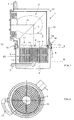
Der Gasheizkessel besteht grundsätzlich und in bekannter Weise aus einem wasserführenden Gehäuse 1, in dem eine mit Brenner 2 bestückte Brennkammer 3 und zwischen dieser und dem Abzugsanschlußstutzen 4 einer Abgassammelkammer 5 ein von den Wärmetauschmedien durchströmbarer Nachschaltwärmetauscher NT mit Zu- und Abströmanschlüssen 6, 7 für das zu erwärmende Medium angeordnet ist.The gas boiler basically and in a known manner consists of a water-carrying
Für einen solchen Gasheizkessel ist nun wesentlich, daß der mindestens eine Nachschaltwärmetauscher NT in Form einer axial gasdurchströmbaren, zwischen zwei parallelen Ebenen E spiralförmig gewickelten Tasche 9 ausgebildet und deren in bezug auf deren Querschnittsbreite B wesentlich größere Querschnittshauptachse HA paralle zur Wickelachse WA gerichtet und der Nachschaltwärmetauscher NT in der ungekühlten Abgassammelkammer 5 angeordnet und diese als separate Baueinheit dem wasserführenden Gehäuse 1 zugeordnet ist, wobei der vom wärmezuführenden Medium angeströmte Gesamtquerschnitt des Nachschaltwärmetauschers NT im wesentlichen dem Öffnungsquerschnitt 8 der gegen den Nachschaltwärmetauscher NT offenen und im Querschnitt kreisförmigen Brennkammer 3 entspricht.For such a gas boiler, it is now essential that the at least one secondary heat exchanger NT is designed in the form of a
Dargestellt ist in Fig. 1 die bevorzugte Ausführungsform, bei der die Abgassammelkammer 5 dem wasserführenden Gehäuse 1 unter Zwischenschaltung einer Ringdichtung 18 abgedichtet lösbar zugeordnet ist, wobei die beiden Teile durch Spannschlösser 16 zusammengehalten sind.1 shows the preferred embodiment in which the exhaust
Bei diesem Ausführungsbeispiel dient die Planspirale bzw. die zu einer im Sinne der Fig. 2 zu einer Spirale gewickelte Tasche 9 als NT zur Durchleitung des Heizungsrücklaufes, der am Zuströmanschluß 6 angeschlossen ist und nach Passage der Planspirale vom Zentrum aus durch ein Leitungsstück 17 in den Innenraum 10 des Gehäuses 1 gelangt und erwärmt diesen durch den Abströmanschluß 7 (Vorlauf) verläßt. Sofern die Planspirale zur Bereitung von Brauchwasser dienen soll, ist der Zuströmanschluß 6 der Kaltwasseranschluß, und der Abströmanschluß 7 sitzt statt des Leitungsstückes 17 direkt an der Planspirale und dient als Warmwasserabzugsanschluß von dem Warmwasser entweder direkt oder über einen Brauchwasserpufferspeicher (nicht dargestellt) gezapft werden kann.In this embodiment, the plane spiral or the
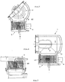
Das gleiche Bauprinzip zeigen die anderen Ausführungsbeispiele nach den Fig. 3 bis 6, in denen sich entsprechende Elemente mit entsprechenden Bezugszeichen versehen sind. Hierbei sind allerdings die als separate Baueinheiten erkennbaren Abgassammelkammern 5 direkt mit dem jeweiligen wasserführenden Gehäuse 1 verschweißt dargestellt, was ein äußeres Leitungsstück 17 entbehrlich macht, da hier, wie mit Pfeilen angedeutet, eine Direktverbindung zwischen Planspirale und wasserführendem Innenraum 10 hergestellt werden kann.The same construction principle is shown in the other exemplary embodiments according to FIGS. 3 to 6, in which corresponding elements are included corresponding reference numerals are provided. Here, however, the exhaust
Eine Ausgestaltung derart, daß der Nachschaltwärmetauscher NT aus zwei unabhängig voneinander durchströmbaren Taschen 9, 9' gebildet ist, von denen die eine mit dem wasserführenden Innenraum 10 des Gehäuses 1 in Verbindung steht und die andere 9' mit Brauchwasserzu- und -abfuhranschlüssen 6', 7' versehen ist, wobei die beiden Taschen 9, 9' in bezug auf die axiale Gasdurchströmrichtung hintereinander angeordnet sind, ist in Fig. 3 verdeutlicht. Wie mit Pfeilen verdeutlicht, dient die untere Tasche 9 für die Erwärmung des rücklaufenden Heizungswassers und die obere Tasche 9' für die des Brauchwassers.An embodiment such that the post-heat exchanger NT is formed from two
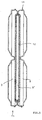
Eine besondere Ausführungsform der Planspirale zeigt im Schnitt die Fig. 9. Hiernach ist der mit dem wasserführenden Innenraum 10 des Gehäuses 1 in Verbindung stehende Nachschaltwärmetauscher NT doppelsträngig ausgebildet und zwischen diesen beiden Strängen 11, mit diesen beidseitig in flächigem Wärmeleitkontakt stehend, ist ein dritter Strang 12 mit den Brauchwasserzu- und - abfuhranschlüssen 6', 7' angeordnet. Alle drei Stränge 11, 12 werden hierbei gemeinsam zu einer Spirale gewickelt. Die Wärmeübertragung an das Brauchwasser bzw. die brauchwasserführende Tasche erfolgt hierbei nicht direkt durch das Heizgas, sondern durch Wärmeleitkontakt der beidseitig an der Tasche 9' flächig anliegenden Taschen 9. Bei dieser Ausführungsform ist es im übrigen auch möglich, die Stränge 11, 12 separat zu wickeln und den Strang 11 in Spiralform zwischen die ebenfalls bereits in Spiralform befindlichen Stänge 12 einzuschieben, wofür unten die Stränge 11 keine Wülste, wie dargestellt, aufweisen dürfen.A special embodiment of the plane spiral is shown in section in FIG. 9. Thereafter, the secondary heat exchanger NT, which is connected to the water-carrying
Bei allen Ausführungsbeispielen bis auf das der Fig. 6, die einen atmosphärischen Gasheizkessel darstellt, ist das wasserführende Gehäuse 1 gewissermaßen auf die Planspirale bzw. Planspiralen enthaltende Abgassammelkammer 5 aufgesattelt, d.h., die Abgassammelkammer 5 ist unter dem wasserführenden Gehäuse 1 angeordnet, das mit der Brennkammer 3 in Form eines Winkel- oder Bogenstückes 13, 13' ausgebildet und der Brenner 2 mit seiner Achse 14 senkrecht oder geneigt zur Wickelachse 15 des/der Nachschaltwärmetauscher NT orientiert angeordnet ist. Als Brenner werden dabei solche mit den dargestellten Formen benutzt, deren wirksame Brennerfläche aus Metallgewebe besteht. Auf diese Weise wirkt der Brenner mit seiner Wärmestrahlung nicht nur unmittelbar gegen die wassergekühlten Wände des Gehäuses 1, sondern auch gegen die Planspirale, und der Heizkessel erhält geringe Höhenabmessungen. Bei einer Leistungsgröße für bspw. 7 bis 12 KW sind die in den Fig. 1 bis 5 gezeigten Heizkessel etwa nur doppelt so groß, wie dargestellt.In all of the exemplary embodiments except for that of FIG. 6, which represents an atmospheric gas heating boiler, the water-carrying
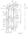
Was nun die den Nachschaltwärmetauscher NT bildende Planspirale selbst betrifft, so wird dazu auf Fig. 8 verwiesen, wonach die in bezug auf die Wickelachse 15 innere Wand 20 oben und unten nach außen abgekröpfte, maximal der Breite B des wasserführenden Innenraumes 21 entsprechende Ränder 22 aufweist. Die äußere Wand 23 hat nach innen abgekröpfte Ränder 24 mit maximal halber Breite B, welche Ränder 24 die Ränder 22 der inneren Wand 20 übergreifen oder mit diesen fluchten und mit diesen flüssigkeitsdicht verbunden sind. In den gasführenden, zu- und abströmseitig offenen Innenraum 25' weisende Wellenprägungen 27 beider Wände 20, 23 sind mit Distanz D zu den Rändern 22, 24 in den Wänden 20, 23 im wesentlichen parallel zur Wickelachse 15 sich gegenseitig abstützend, angeordnet und ausgebildet, und der wasserführende Innenraum 25 ist an beiden Enden der Planspirale bis auf die angesetzten Vor- und Rücklaufanschlußöffnungen verschlossen. Ein solcher NT stellt sich in Draufsicht gemäß Fig. 2 dar, aus der auch erkennbar ist, daß das innere Wickelende der Spirale natürlich nicht im Zentrum der Spirale beginnt, sondern an einem Füllkörper 26, der auch als Hohlkörper ausgebildet sein kann und den Rücklaufanschluß bildet. Eine Wicklung vom Zentrum aus verbietet sich von selbst, da dafür die Biegeradien zu klein wären. Im dargestellten Ausführungsbeispiel nach Fig. 8 handelt es sich um einen NT mit relativ großer Höhe H, und in Rücksicht darauf ist die innere Wand 20 mit einer sich senkrecht zur Wickelachse 15 erstreckenden mittigen Wellenprägung 27 versehen, die in ihrer Tiefe der Breite B des wasserführenden Innenraumes 25 entspricht. Diese Wellenprägung 27 stützt die Wand 23 mittig ab und teilt den wasserführenden Innenraum 25, so daß dieser vom Füllkorper 26 (Rücklaufanschluß) aus in zwei entsprechenden spiralförmigen Parallelströmen durchströmt wird und aus den beiden Öffnungen in den wasserführenden Innenraum 10 des Heizkessels gelangt. Die aus der Brennkammer 3 des Heizkessels in den NT eintretenden Heizgase durchströmen den nach beiden Seiten offenen, gasführenden Innenraum 25' parallel zur Wickelachse 15. Durch diese Ausbildung der Tasche 9 läßt sich diese kontinuierlich wickeln und verschweißen, wird danach mit einem angepaßten Hüllblech 19 umgeben und damit in die Abgassammelkammer 5 eingesetzt, wobei das Hüllblech 19 (siehe Fig. 1 bis 6) den Einbau in die Abgassammelkammer 5 vorteilhaft erleichtert. Ausbildung und Herstellung der Planspiralen sind dabei immer gleich, und zwar unabhängig davon, ob die Planspirale zur Durchleitung von Heizungswasser oder von Brauchwasser dienen soll.With regard to the plane spiral forming the post-heat exchanger NT itself, reference is made to FIG. 8, according to which the
Sofern der NT gleichzeitig zur Erwärmung von Brauchwasser dienen soll, wie zu Fig. 9 bereits vorbeschrieben, besteht dieser in bevorzugter Ausführungsform gemäß Fig. 10 darin, daß die spiralförmig gewickelte Tasche 9 aus zwei Taschenteilen 9' gebildet ist, die mit ihren gegeneinander gerichteten Flanken 28 einen Brauchwasserkanal 29 begrenzen, wobei die beiden Taschenteile 9' im Querschnittsprofil bis auf die an- und abströmseitigen Verschlußränder 30 formidentisch ausgebildet sind.If the NT is also to be used for heating domestic water, as already described for FIG. 9, this consists in a preferred embodiment according to FIG. 10 in that the
Die den Brauchwasserkanal 29 begrenzenden Flanken 28 der beiden Taschenteile 9' sind, wie dargestellt, an ihren Rändern mit gegeneinander gerichteten und miteinander verschweißten obere und untere Verschlüsse des Brauchwasserkanales 29 bildenden Wulstprägungen 31 versehen. Im dadurch gegebenen Zwickel 31' ist eine Schweißnaht aus Zusatzschweißmaterial (nicht dargestellt) verlegt.The
Ferner sind bei diesem Ausführungsbeispiel die gasbeaufschlagten Flanken F der beiden Taschenteile 9' mit sich in Wickelrichtung erstreckenden Nuteinprägungen 32 versehen, wobei zwischen den Nuteinprägungen 32 der benachbarten Flanke F profilangepaßte Distanzdrähte 33 angeordnet sind.Furthermore, in this exemplary embodiment, the gas-charged flanks F of the two pocket parts 9 'are provided with
Die Nuteinprägungen 32 haben dabei eine wesentlich geringere Tiefe als die Wellenprägungen 27 der gasbeaufschlagten Flanken F, denn sonst wäre die Heizgaspassage unterbunden. Da die Wellenprägungen 27 eine relativ geringe Höhe von ewa nur 3 bis 4 mm bei einer Blechstärke von etwa 0,8 bis 1 mm haben, würde der Gaspassagequerschnitt der Gesamtspirale bei dieser Kompaktausbildung zu klein, d.h., daß man auf diese Weise durch die Anordnung der Distanzdrähte, ohne die Höhe der Wellenprägungen vergrößern zu müssen, den Gaspassagequerschnitt entsprechend vergrößern müßte. Abgesehen davon führen die Distanzdrähte zu einer verbesserte Gaswirbelung.The groove embossments 32 have a much smaller depth than the
Wie zu Fig. 8 bereits vorbeschrieben und bei einer Höhe H der Tasche 9 bzw. der Taschenteile 9' von etwa 110 bis 130 mm, sind auch bei dieser Ausführungsform die Wickelachsenseitigen Flanken WF der beiden Taschenteile 9' jeweils mittig und mit einer bis zur benachbarten wasserseitigen Wand W eingetieften und sich in Wickelrichtung erstreckenden Stützprägung versehen.As already described for FIG. 8 and at a height H of the
Die Verschlußränder 30 sind, wie dargestellt, ausgebildet, d.h., diese sind mit kurzen, nach außen gerichteten Abkröpfungen 31'' versehen, die nach dem Zusammenführen der beteiligten Wände beim Wickeln gleichzeitig ohne Zusatzwerkstoff einfach niedergeschmolzen werden, wodurch exponiert hervorstehende Verbindungsränder vermieden werden, die insbesondere gasanströmseitig nachteilig wären. Diese Ausführungsform wird im übrigen auch bei allen vorbeschriebenen anderen Ausführungsformen des NT bevorzugt.The closure edges 30 are, as shown, formed, that is, they are provided with short, outwardly directed bends 31 '' which, after the walls involved have been brought together during winding, are simply melted down without filler material, thereby avoiding exposed protruding connecting edges would be particularly disadvantageous on the gas inflow side. This embodiment is also preferred in all of the other embodiments of the NT described above.
Um den vorbeschriebenen Gasheizkessel, ohne dabei Wesentliches ändern zu müssen, auch als Brennwertkessel nutzen oder gezielt eine spezielle Abgastemperatur einstellen zu können, sind am Hüllblech 19 Gasausströmöffnungen 40 angeordnet, denen außen am Hüllblech 19 mindestens eine verstellbare Schließblende 41 zugeordnet ist, wobei "mindestens eine" die grundsätzliche Möglichkeit beinhaltet, jede der Gasausströmöffnungen 40 mit einer separaten Schließblende auszustatten, was jedoch mit einem beträchtlichen Aufwand verbunden wäre. Im übrigen könnten die Gas ausströmöffnungen 40 auch längs mindestens zweier Umfangsmantellinien 42 angeordnet werden, was nicht besonders dargestellt ist, da ohne weiteres vorstellbar.In order to be able to use the gas boiler described above as a condensing boiler or to set a specific exhaust gas temperature without having to make any essential changes, 19
Bevorzugt wird eine Ausführungsform gemäß Fig. 12 B, bei der die Schließblende 41 in Form eines parallel zur Hüllblechachse 43 verstellbaren Ringes 44 ausgebildet ist. Gleiches gilt auch für die besondere Ausführungsform nach Fig. 12 E, bei der die Gasausströmöffnungen 40 als zur Hüllblechachse 43 achsparallele Schlitze 45 ausgebildet sind und die achsparallel am Hüllblech 19 verstellbare ringförmige Schließblende 41 eine Breite B hat, die der Länge L der Schlitze 45 entspricht.An embodiment according to FIG. 12B is preferred in which the
Die Verschiebe- bzw. Verstellrichtungen der Schließblenden sind mit Pfeilen P verdeutlicht. Die Ausführungsform nach Fig. 12 E hat dabei die Besonderheit, daß, abgesehen von totaler Schließung (dargestellt) oder Öffnung der Schlitze 45, je nachdem, ob die Schließblende 41 (gestrichelt angedeutet) nach oben oder unten verschoben wird, Abgas aus dem periphären Durchströmspalt 46 weiter oben oder weiter unten aus dem Hüllbelch 19 direkt in die Abgassammelkammer ausströmen kann. Diese achsparallele Verschiebbarkeit der Schließblende trägt im übrigen am einfachsten der in Fig. 11 verdeutlichten Form des Hüllbleches 19 Rechnung, die sich durch die Spiralform der die Planspirale bildenden Tasche ergibt.The directions of displacement or adjustment of the closing panels are indicated by arrows P. The embodiment according to FIG. 12 E has the peculiarity that, apart from total closure (shown) or opening of the
Abgesehen davon ist es aber auch gemäß Fig. 12 C möglich, die Schließblende 41 in Form eines um das Hüllblech 19 drehbaren Ringes 44 '' auszubilden und diesen mit den Gasausströmöffnungen 40 des Hüllbleches 19 in Form und Anordnung entsprechenden Durchströmöffnungen 40 ' zu versehen. Die am Hüllblech 19 vorhandene Stufe 19' (siehe Fig. 11) stellt dabei für eine Drehung kein Hindernis dar, da man bspw. den Ring 44'' auch als radial etwas aufspreizbare Manschette ausbilden und aufgespreizt verstellen und danach wieder festspannen kann.Apart from this, it is also possible according to FIG. 12 C to design the closing
Um sicherzustellen, daß die jeweilige Schließblende ihre Stellung bei wechselnden Temperaturbelastungen beibehält, ist diese mit mindestens einem Fixierungselement 47 versehen, wofür bspw. eine einfache kleine Blechschraube genügt.In order to ensure that the respective closing panel maintains its position in the event of changing temperature loads, it is provided with at least one fixing
Claims (14)
dadurch gekennzeichnet,
daß der mindestens eine Nachschaltwärmetauscher (NT) in Form einer axial gasdurchströmbaren, zwischen zwei parallelen Ebenen (E) spiralförmig gewickelten Tasche (9) ausgebildet und deren in bezug auf deren Querschnittsbreite (B) vielfach größere Querschnittshauptachse (HA) parallel zur Wickelachse (WA) gerichtet und der Nachschaltwärmetauscher (NT) in der ungekühlten Abgassammelkammer (5) angeordnet und diese als separate Einheit dem wasserführenden Gehäuse (1) zugeordnet ist, wobei der vom wärmezuführenden Medium angeströmte Gesamtquerschnitt des Nachschaltwärmetauschers (NT) im wesentlichen dem Öffnungsquerschnitt (8) der gegen den Nachschaltwärmetauscher (NT) offenen und im Querschnitt kreisförmigen Brennkammer (3) entspricht.Gas boiler, consisting of a water-bearing housing (1) in which a combustion chamber (3) equipped with a burner (2) and between this and the exhaust connection piece (4) of an exhaust gas collection chamber (5) a secondary heat exchanger (NT) through which the heat exchange media can flow and with and outflow connections (6, 7) for the medium to be heated,
characterized,
that the at least one secondary heat exchanger (NT) is designed in the form of an axially gas-flowable pocket (9) which is spirally wound between two parallel planes (E) and whose cross-sectional width (B) is often larger in cross-section main axis (HA) parallel to the winding axis (WA) directed and the secondary heat exchanger (NT) arranged in the uncooled exhaust gas collection chamber (5) and this is assigned as a separate unit to the water-carrying housing (1), the total cross-section of the secondary heat exchanger (NT) flowing from the heat-supplying medium essentially being the opening cross-section (8) of the opposite the post-heat exchanger (NT) corresponds to an open combustion chamber (3) with a circular cross section.
dadurch gekennzeichnet,
daß die mit dem Nachschaltwärmetauscher (NT) bestückte Abgassammelkammer (5) dem Gehäuse (1) abgedichtet lösbar zugeordnet ist.Boiler according to claim 1,
characterized,
that the exhaust gas collecting chamber (5) equipped with the secondary heat exchanger (NT) is assigned to the housing (1) in a sealed, detachable manner.
dadurch gekennzeichnet,
daß der Abströmanschluß (7) des Nachschaltwärmetauschers (NT) mit dem wasserführenden Innenraum (10) des Gehäuses (1) verbunden ist.Boiler according to claim 1 or 2,
characterized,
that the outflow connection (7) of the secondary heat exchanger (NT) is connected to the water-carrying interior (10) of the housing (1).
dadurch gekennzeichnet,
daß der Nachschaltwärmetauscher (NT) aus zwei unabhängig voneinander durchströmbaren Taschen (9, 9') gebildet ist, von denen die eine mit dem wasserführenden Innenraum (10) des Gehäuses (1) in Verbindung steht und die andere (9') mit Brauchwasserzu- und -abfuhranschlüssen (6', 7') versehen ist.Boiler according to one of claims 1 to 3,
characterized,
that the secondary heat exchanger (NT) is formed from two pockets (9, 9 ') which can flow through independently of one another, one of which is connected to the water-carrying interior (10) of the housing (1) and the other (9') with process water supply and discharge connections (6 ', 7') is provided.
dadurch gekennzeichnet,
daß der mit dem wasserführenden Innenraum (10) des Gehäuses (1) in Verbindung stehende Nachschaltwärmetauscher (NT) doppelsträngig ausgebildet und zwischen diesen beiden Strängen (11), mit diesen beidseitig in flächigem Wärmeleitkontakt stehend, ein dritter Strang (12) mit den Brauchwasserzu- und -abfuhranschlüssen (6', 7') angeordnet ist.Boiler according to claim 4,
characterized,
that the secondary heat exchanger (NT) connected to the water-carrying interior (10) of the housing (1) is double-stranded and a third strand (12) with the hot water supply between these two strands (11), which is in flat thermal contact with them on both sides. and discharge connections (6 ', 7') is arranged.
dadurch gekennzeichnet,
daß die spiralförmig gewichelte Tasche (9) aus zwei Taschenteilen (9') gebildet ist, die mit ihren gegeneinander gerichteten Flanken (28) einen Brauchwasserkanal (29) begrenzen.Boiler according to one of claims 1 to 3,
characterized,
that the spirally coiled pocket (9) is formed from two pocket parts (9 ') which, with their mutually facing flanks (28), delimit a process water channel (29).
dadurch gekennzeichnet,
daß die beiden Taschenteile (9') im Querschnittsprofil bis auf die an- und abströmseitigen Verschlußränder (30) formidentisch ausgebildet sind.Boiler according to claim 8,
characterized,
that the two pocket parts (9 ') are of identical shape in cross-sectional profile except for the upstream and downstream closing edges (30).
dadurch gekennzeichnet,
daß die den Brauchwasserkanal (29) begrenzenden Flanken (28) der beiden Taschenteile (9') an ihren Rändern mit gegeneinander gerichteten und miteinander verschweißten obere und untere Verschlüsse des Brauchwasserkanales (29) bildenden Wulstprägungen (31) versehen sind.Boiler according to claim 7,
characterized,
that the sides (28) of the two pocket parts (9 ') delimiting the process water channel (29) are provided at their edges with mutually directed and welded upper and lower closures of the process water channel (29) forming bead embossments (31).
dadurch gekennzeichnet,
daß die gasbeaufschlagten Flanken (F) der beiden Taschenteile (9') mit sich in Wickelrichtung erstreckenden Nuteinprägungen (32) versehen und zwischen den Nuteinprägungen (32) der benachbarten Flanken (F) profilangepaßte Distanzdrähte (33) angeordnet sind.Boiler according to one of claims 6 to 8,
characterized,
that the gas-loaded flanks (F) of the two pocket parts (9 ') are provided with groove impressions (32) extending in the winding direction and profile-adapted spacer wires (33) are arranged between the groove impressions (32) of the adjacent flanks (F).
dadurch gekennzeichnet,
daß die Abgassammelkammer (5) unter dem wasserführenden Gehäuse (1) angeordnet ist, das mit der Brennkammer (3) in Form eines Winkel- oder Bogenstückes (13, 13') ausgebildet und der Brenner (2) mit seiner Achse (14) senkrecht oder geneigt zur Wickelachse (15) des/der Nachschaltwärmetauscher (NT) orientiert angeordnet ist.Boiler according to one of claims 1 to 9,
characterized,
that the exhaust gas collection chamber (5) is arranged under the water-carrying housing (1), which is formed with the combustion chamber (3) in the form of an angle or arc piece (13, 13 ') and the burner (2) with its axis (14) perpendicular or is arranged at an angle to the winding axis (15) of the secondary heat exchanger (NT).
dadurch gekennzeichnet,
daß der mindestens eine spiralförmig gewickelte Nachschaltwärmetauscher (NT) in einem Hüllblech (19) angeordnet und mit diesem in der Abgassammelkammer (5) eingesetzt ist.Boiler according to one of claims 1 to 10,
characterized,
that the at least one spirally wound secondary heat exchanger (NT) is arranged in a cladding sheet (19) and is inserted with it in the exhaust gas collecting chamber (5).
dadurch gekennzeichnet,
daß am Hüllblech (19) längs mindestens einer der mittleren Umfangsmantellinien (42) ringsum mehrere Gasausströmöffnungen (40) angeordnet sind und diesen außen am Hüllblech (19) mindestens eine verstellbare Schließblende (41) zugeordnet ist.Boiler according to claim 11,
characterized,
that a plurality of gas outflow openings (40) are arranged around the enveloping plate (19) along at least one of the central circumferential surface lines (42) and at least one adjustable closing diaphragm (41) is assigned to the outside of the enveloping plate (19).
dadurch gekennzeichnet,
daß der in der Brennkammer (3) angeordnete Brenner (2) als Strahlungsbrenner eine sphärische Form hat und ein Teil (F) der Brennerfläche über den Anströmquerschnitt des Nachschaltwärmetauschers (NT) angeordnet ist.Boiler according to one of claims 1 to 12,
characterized,
that the burner (2) arranged in the combustion chamber (3) has a spherical shape as a radiation burner and part (F) of the burner surface is arranged over the inflow cross section of the secondary heat exchanger (NT).
dadurch gekennzeichnet,
daß die Heizwasser führende(n) Tasche(n) aus Leichtmetallblech, wie Alu-Blech, und die Brauchwasser führende(n) Tasche(n) aus Edelstahlblech gebildet ist (sind).Boiler according to one of claims 4, 5 and 10 to 13,
characterized,
that the pocket (s) carrying heating water is made of light metal sheet, such as aluminum sheet, and the pocket (s) carrying hot water is made of stainless steel sheet.
Applications Claiming Priority (4)
| Application Number | Priority Date | Filing Date | Title |
|---|---|---|---|
| DE9210972U | 1992-08-17 | ||
| DE9210972U DE9210972U1 (en) | 1992-08-17 | 1992-08-17 | Gas boiler |
| DE19924229146 DE4229146C1 (en) | 1992-09-01 | 1992-09-01 | Gas boiler |
| DE4229146 | 1992-09-01 |
Publications (2)
| Publication Number | Publication Date |
|---|---|
| EP0583574A1 true EP0583574A1 (en) | 1994-02-23 |
| EP0583574B1 EP0583574B1 (en) | 1995-12-13 |
Family
ID=25918114
Family Applications (1)
| Application Number | Title | Priority Date | Filing Date |
|---|---|---|---|
| EP93109912A Expired - Lifetime EP0583574B1 (en) | 1992-08-17 | 1993-06-22 | Gas-fired boiler |
Country Status (5)
| Country | Link |
|---|---|
| EP (1) | EP0583574B1 (en) |
| AT (1) | ATE131591T1 (en) |
| DE (1) | DE59301157D1 (en) |
| DK (1) | DK0583574T3 (en) |
| ES (1) | ES2080560T3 (en) |
Cited By (2)
| Publication number | Priority date | Publication date | Assignee | Title |
|---|---|---|---|---|
| EP1095229A1 (en) * | 1998-06-15 | 2001-05-02 | AOS Pty. Ltd. | Water jacket assembly |
| CN107850341A (en) * | 2015-07-23 | 2018-03-27 | 庆东纳碧安株式会社 | Heat exchanger |
Citations (4)
| Publication number | Priority date | Publication date | Assignee | Title |
|---|---|---|---|---|
| DE1753242A1 (en) * | 1968-03-07 | 1971-07-15 | Hans Viessmann | Boilers, especially for the use of gaseous fuels |
| EP0028830A1 (en) * | 1979-11-12 | 1981-05-20 | Huber, Markus Gerätebau | Central-heating boiler with infinitely adjustable heating surfaces in the shape of a spiral and cleanable from the outside |
| EP0123995A1 (en) * | 1983-04-27 | 1984-11-07 | Etablissement Agura | Condensing boiler with a spirally coiled heat exchanger part |
| DE3613103A1 (en) * | 1986-04-18 | 1987-10-22 | Hans Weiss | Arrangement for heat transfer in a heat generator |
-
1993
- 1993-06-22 EP EP93109912A patent/EP0583574B1/en not_active Expired - Lifetime
- 1993-06-22 AT AT93109912T patent/ATE131591T1/en not_active IP Right Cessation
- 1993-06-22 DK DK93109912.1T patent/DK0583574T3/en active
- 1993-06-22 ES ES93109912T patent/ES2080560T3/en not_active Expired - Lifetime
- 1993-06-22 DE DE59301157T patent/DE59301157D1/en not_active Expired - Fee Related
Patent Citations (4)
| Publication number | Priority date | Publication date | Assignee | Title |
|---|---|---|---|---|
| DE1753242A1 (en) * | 1968-03-07 | 1971-07-15 | Hans Viessmann | Boilers, especially for the use of gaseous fuels |
| EP0028830A1 (en) * | 1979-11-12 | 1981-05-20 | Huber, Markus Gerätebau | Central-heating boiler with infinitely adjustable heating surfaces in the shape of a spiral and cleanable from the outside |
| EP0123995A1 (en) * | 1983-04-27 | 1984-11-07 | Etablissement Agura | Condensing boiler with a spirally coiled heat exchanger part |
| DE3613103A1 (en) * | 1986-04-18 | 1987-10-22 | Hans Weiss | Arrangement for heat transfer in a heat generator |
Cited By (6)
| Publication number | Priority date | Publication date | Assignee | Title |
|---|---|---|---|---|
| EP1095229A1 (en) * | 1998-06-15 | 2001-05-02 | AOS Pty. Ltd. | Water jacket assembly |
| EP1095229A4 (en) * | 1998-06-15 | 2004-03-10 | Rheem Australia Pty Ltd | Water jacket assembly |
| CN107850341A (en) * | 2015-07-23 | 2018-03-27 | 庆东纳碧安株式会社 | Heat exchanger |
| CN108518855A (en) * | 2015-07-23 | 2018-09-11 | 庆东纳碧安株式会社 | Heat exchanger |
| CN107850341B (en) * | 2015-07-23 | 2021-04-09 | 庆东纳碧安株式会社 | Heat exchanger |
| CN108518855B (en) * | 2015-07-23 | 2021-04-13 | 庆东纳碧安株式会社 | Heat exchanger |
Also Published As
| Publication number | Publication date |
|---|---|
| ES2080560T3 (en) | 1996-02-01 |
| DK0583574T3 (en) | 1996-01-29 |
| DE59301157D1 (en) | 1996-01-25 |
| ATE131591T1 (en) | 1995-12-15 |
| EP0583574B1 (en) | 1995-12-13 |
Similar Documents
| Publication | Publication Date | Title |
|---|---|---|
| EP1979696B1 (en) | Heating device | |
| EP2440855A2 (en) | Sectional boiler | |
| EP2096372A2 (en) | Heating device | |
| EP0576963A1 (en) | Residual heat exchanger for mounting in the boiler casing | |
| EP0583574B1 (en) | Gas-fired boiler | |
| EP2157382A2 (en) | Heating device | |
| EP2438382B1 (en) | Sectional boiler | |
| DE102004046587A1 (en) | heat exchangers | |
| DE4229146C1 (en) | Gas boiler | |
| DE102007010585A1 (en) | Water register e.g. for furnace, heat exchanger, has pipe input, pipe output, flue gas channel, heat exchanger and line connections | |
| DE102008035852A1 (en) | Device for heating a heat carrier for in particular laundry machines and preferred uses of the device | |
| DE2107108A1 (en) | Articulated boiler with a combustion chamber located in the lower part | |
| EP0120435B1 (en) | Shape of fuel gas passages in boilers | |
| DE19505235B4 (en) | condensing boilers | |
| EP0387628B1 (en) | Heater | |
| EP0632239A1 (en) | Hot gas passage | |
| DE4316323C2 (en) | Gas boiler | |
| DE3205121A1 (en) | Heating boiler | |
| DE2324649C2 (en) | Heat exchangers for motor-independent heating systems in motor vehicles | |
| AT406518B (en) | Heating boiler | |
| DE3205122A1 (en) | Heating boiler for liquid or gaseous fuels | |
| WO2000009959A1 (en) | Heating boiler | |
| EP0296276A2 (en) | Boiler | |
| DE1912629C3 (en) | Combustion chamber for a water heater | |
| AT221259B (en) | Tubular heat exchanger element |
Legal Events
| Date | Code | Title | Description |
|---|---|---|---|
| PUAI | Public reference made under article 153(3) epc to a published international application that has entered the european phase |
Free format text: ORIGINAL CODE: 0009012 |
|
| AK | Designated contracting states |
Kind code of ref document: A1 Designated state(s): AT BE CH DE DK ES FR GB IT LI NL SE |
|
| 17P | Request for examination filed |
Effective date: 19931228 |
|
| 17Q | First examination report despatched |
Effective date: 19950428 |
|
| GRAA | (expected) grant |
Free format text: ORIGINAL CODE: 0009210 |
|
| AK | Designated contracting states |
Kind code of ref document: B1 Designated state(s): AT BE CH DE DK ES FR GB IT LI NL SE |
|
| REF | Corresponds to: |
Ref document number: 131591 Country of ref document: AT Date of ref document: 19951215 Kind code of ref document: T |
|
| ET | Fr: translation filed | ||
| REF | Corresponds to: |
Ref document number: 59301157 Country of ref document: DE Date of ref document: 19960125 |
|
| REG | Reference to a national code |
Ref country code: DK Ref legal event code: T3 |
|
| REG | Reference to a national code |
Ref country code: ES Ref legal event code: FG2A Ref document number: 2080560 Country of ref document: ES Kind code of ref document: T3 |
|
| REG | Reference to a national code |
Ref country code: CH Ref legal event code: NV Representative=s name: SCHMAUDER & WANN PATENTANWALTSBUERO |
|
| ITF | It: translation for a ep patent filed |
Owner name: MODIANO & ASSOCIATI S.R.L. |
|
| GBT | Gb: translation of ep patent filed (gb section 77(6)(a)/1977) |
Effective date: 19960321 |
|
| PLBE | No opposition filed within time limit |
Free format text: ORIGINAL CODE: 0009261 |
|
| STAA | Information on the status of an ep patent application or granted ep patent |
Free format text: STATUS: NO OPPOSITION FILED WITHIN TIME LIMIT |
|
| 26N | No opposition filed | ||
| PGFP | Annual fee paid to national office [announced via postgrant information from national office to epo] |
Ref country code: BE Payment date: 19990526 Year of fee payment: 7 |
|
| PGFP | Annual fee paid to national office [announced via postgrant information from national office to epo] |
Ref country code: NL Payment date: 19990603 Year of fee payment: 7 |
|
| PGFP | Annual fee paid to national office [announced via postgrant information from national office to epo] |
Ref country code: ES Payment date: 19990609 Year of fee payment: 7 |
|
| PGFP | Annual fee paid to national office [announced via postgrant information from national office to epo] |
Ref country code: GB Payment date: 19990614 Year of fee payment: 7 |
|
| PGFP | Annual fee paid to national office [announced via postgrant information from national office to epo] |
Ref country code: SE Payment date: 19990617 Year of fee payment: 7 Ref country code: CH Payment date: 19990617 Year of fee payment: 7 |
|
| PGFP | Annual fee paid to national office [announced via postgrant information from national office to epo] |
Ref country code: DK Payment date: 19990625 Year of fee payment: 7 |
|
| PGFP | Annual fee paid to national office [announced via postgrant information from national office to epo] |
Ref country code: FR Payment date: 19990629 Year of fee payment: 7 |
|
| PGFP | Annual fee paid to national office [announced via postgrant information from national office to epo] |
Ref country code: AT Payment date: 19990630 Year of fee payment: 7 |
|
| PG25 | Lapsed in a contracting state [announced via postgrant information from national office to epo] |
Ref country code: GB Free format text: LAPSE BECAUSE OF NON-PAYMENT OF DUE FEES Effective date: 20000622 Ref country code: DK Free format text: LAPSE BECAUSE OF NON-PAYMENT OF DUE FEES Effective date: 20000622 Ref country code: AT Free format text: LAPSE BECAUSE OF NON-PAYMENT OF DUE FEES Effective date: 20000622 |
|
| PG25 | Lapsed in a contracting state [announced via postgrant information from national office to epo] |
Ref country code: SE Free format text: LAPSE BECAUSE OF NON-PAYMENT OF DUE FEES Effective date: 20000623 Ref country code: ES Free format text: THE PATENT HAS BEEN ANNULLED BY A DECISION OF A NATIONAL AUTHORITY Effective date: 20000623 |
|
| PG25 | Lapsed in a contracting state [announced via postgrant information from national office to epo] |
Ref country code: LI Free format text: LAPSE BECAUSE OF NON-PAYMENT OF DUE FEES Effective date: 20000630 Ref country code: CH Free format text: LAPSE BECAUSE OF NON-PAYMENT OF DUE FEES Effective date: 20000630 Ref country code: BE Free format text: LAPSE BECAUSE OF NON-PAYMENT OF DUE FEES Effective date: 20000630 |
|
| BERE | Be: lapsed |
Owner name: VIESSMANN HANS Effective date: 20000630 |
|
| PG25 | Lapsed in a contracting state [announced via postgrant information from national office to epo] |
Ref country code: NL Free format text: LAPSE BECAUSE OF NON-PAYMENT OF DUE FEES Effective date: 20010101 |
|
| GBPC | Gb: european patent ceased through non-payment of renewal fee |
Effective date: 20000622 |
|
| REG | Reference to a national code |
Ref country code: CH Ref legal event code: PL |
|
| EUG | Se: european patent has lapsed |
Ref document number: 93109912.1 |
|
| REG | Reference to a national code |
Ref country code: DK Ref legal event code: EBP |
|
| PG25 | Lapsed in a contracting state [announced via postgrant information from national office to epo] |
Ref country code: FR Free format text: LAPSE BECAUSE OF NON-PAYMENT OF DUE FEES Effective date: 20010228 |
|
| NLV4 | Nl: lapsed or anulled due to non-payment of the annual fee |
Effective date: 20010101 |
|
| REG | Reference to a national code |
Ref country code: FR Ref legal event code: ST |
|
| PGFP | Annual fee paid to national office [announced via postgrant information from national office to epo] |
Ref country code: DE Payment date: 20010704 Year of fee payment: 9 |
|
| REG | Reference to a national code |
Ref country code: ES Ref legal event code: FD2A Effective date: 20020204 |
|
| PG25 | Lapsed in a contracting state [announced via postgrant information from national office to epo] |
Ref country code: DE Free format text: LAPSE BECAUSE OF NON-PAYMENT OF DUE FEES Effective date: 20030101 |
|
| PG25 | Lapsed in a contracting state [announced via postgrant information from national office to epo] |
Ref country code: IT Free format text: LAPSE BECAUSE OF NON-PAYMENT OF DUE FEES;WARNING: LAPSES OF ITALIAN PATENTS WITH EFFECTIVE DATE BEFORE 2007 MAY HAVE OCCURRED AT ANY TIME BEFORE 2007. THE CORRECT EFFECTIVE DATE MAY BE DIFFERENT FROM THE ONE RECORDED. Effective date: 20050622 |