EP0120435B1 - Shape of fuel gas passages in boilers - Google Patents
Shape of fuel gas passages in boilers Download PDFInfo
- Publication number
- EP0120435B1 EP0120435B1 EP84102993A EP84102993A EP0120435B1 EP 0120435 B1 EP0120435 B1 EP 0120435B1 EP 84102993 A EP84102993 A EP 84102993A EP 84102993 A EP84102993 A EP 84102993A EP 0120435 B1 EP0120435 B1 EP 0120435B1
- Authority
- EP
- European Patent Office
- Prior art keywords
- profiles
- heating gas
- wall
- gas flue
- webs
- Prior art date
- Legal status (The legal status is an assumption and is not a legal conclusion. Google has not performed a legal analysis and makes no representation as to the accuracy of the status listed.)
- Expired
Links
Images

Classifications
-
- F—MECHANICAL ENGINEERING; LIGHTING; HEATING; WEAPONS; BLASTING
- F24—HEATING; RANGES; VENTILATING
- F24H—FLUID HEATERS, e.g. WATER OR AIR HEATERS, HAVING HEAT-GENERATING MEANS, e.g. HEAT PUMPS, IN GENERAL
- F24H1/00—Water heaters, e.g. boilers, continuous-flow heaters or water-storage heaters
- F24H1/22—Water heaters other than continuous-flow or water-storage heaters, e.g. water heaters for central heating
- F24H1/24—Water heaters other than continuous-flow or water-storage heaters, e.g. water heaters for central heating with water mantle surrounding the combustion chamber or chambers
- F24H1/26—Water heaters other than continuous-flow or water-storage heaters, e.g. water heaters for central heating with water mantle surrounding the combustion chamber or chambers the water mantle forming an integral body
- F24H1/263—Water heaters other than continuous-flow or water-storage heaters, e.g. water heaters for central heating with water mantle surrounding the combustion chamber or chambers the water mantle forming an integral body with a dry-wall combustion chamber
Definitions
- the invention relates to a heating gas train for heating boilers according to the preamble of the main claim.
- Such heating gas flues for heating boilers are known, for example, from DE-A 1 778 832.
- the longitudinal ribs are formed by a cylindrically rolled sheet metal blank, which is often folded to form the longitudinal ribs, a sealed space being present between the folded tube and the adjacent water-cooled wall to increase the heating surface temperature and thus to reduce the risk of condensate formation , in which an insulating layer can optionally be arranged, d. H. there is no direct heat-conducting connection between the folded tube and the water-cooled wall.
- Heating gas flues which are divided into individual channels by longitudinal ribs, have proven themselves and have been introduced on the market.
- Such heating boilers are operated today with so-called sliding temperature and are therefore referred to as low-temperature boilers.
- Such heating boilers can even be completely switched off in the most modern design and provided with a corrosion protection insert which consists of a cast body which is pressed or shrunk into the tubular insert made of sheet steel (DE-A 2 948 864).
- a corrosion protection insert which consists of a cast body which is pressed or shrunk into the tubular insert made of sheet steel (DE-A 2 948 864).
- a corrosion protection insert which consists of a cast body which is pressed or shrunk into the tubular insert made of sheet steel (DE-A 2 948 864).
- a corrosion protection insert which consists of a cast body which is pressed or shrunk into the tubular insert made of sheet steel (DE-A 2 948 864).
- the invention is based on the object, while maintaining the above construction principle, to improve a heating gas flue of the type mentioned in that heating boilers provided with such trains, taking into account the corrosion protection requirements, can also be operated as low-temperature boilers with a sliding temperature and ensure that in certain areas there are different heat transfers.
- This object is achieved with a heating gas flue of the type mentioned according to the invention by the features stated in the characterizing part of the main claim.
- Advantageous further developments result from the subclaims.
- U-shaped profiles are known from DE-A 15 01 676 and 20 25 472, but these profiles form the wall itself in the boilers in question, which separates the water-carrying from the gas-carrying space.
- the reason for the design of the heating gas flues according to the invention was the aforementioned limits, this should not rule out that the solution principle according to the invention cannot also be used for heating boilers with smaller output ranges.
- the design principle according to the invention can also be used not only for trains which have only a water-cooled wall, but also for trains which have water-cooled walls on the opposite side.
- the profiles are used on the one hand to form the heating gas flues, but on the other hand their webs placed on the water-carrying wall simultaneously form a largely condensation-preventing double wall on the water-carrying draft wall, wherein, as will be explained in more detail, a specifically metered heat transfer to the wall takes place.
- a specifically metered heat transfer to the wall takes place. which also has the effect during start-up processes during operation, particularly in the low-temperature area of the boiler, that the areas lying towards the fume cupboard side can heat up more quickly because of the lower heat transfer there, which counteracts or largely prevents the accumulation of condensate.
- the draft wall is rounded to form a tube or partial tube and closed with a longitudinal weld seam
- a multitude of heating gas flues with approximately triangular cross sections are created around the pot-like combustion chamber to be used later, each alternating with their distal base points against the combustion chamber and are directed against the wall.
- the rear cover 25 is provided with a flue gas outlet connection 26.
- the deflection chamber 27 is arranged in the tube formed by the wall on the burner side (burner not shown).
- the pot-like combustion chamber 28 sits in the free space between the heating gas flues 8, and the flue gas collecting chamber 28 'is located behind it.
- This boiler structure is not absolutely essential, just as the combustion chamber 28 must be cylindrical and the heating gas flues 8 must be arranged in a ring structure. Possibly.
- the walls of the combustion chamber can also be designed as water-carrying double walls, the interior of which is connected in a suitable manner to the other interior of the housing 22. This would be the case in which the heating gas flues 8 are delimited on both sides by water-cooled walls 3, 3 '.
- the sheet metal blanks for the rib profiles 1 look like they can be seen in FIG. 2 before they are deformed into U-profiles.
- the side slots are used to compensate for thermal expansion, but are not absolutely necessary.
- annular shell 30 can advantageously be arranged either completely or, as shown, in part freely projecting in the area of the flue gas collecting chamber 28 ', but for which it is essential that its inner edge is welded to the profiles 1, to ensure a flow of heat from the profiles into the shell 30, so that this can also heat up quickly.
- thermally connected in some areas is to be understood as the slot welding connection described above, but it is also possible, and this is also preferred because of the much lower expenditure, that the base webs 2 with, for example, a tungsten electrode (i.e. without the addition of additional welding material ) to be welded or melted.
- the attachment of longitudinal welding slots 16 of different sizes and distances can be omitted, and the attachment takes place in such a way that the tacking area or the resulting thermal bridge 5 becomes narrower or smaller from front to back. This can be accomplished easily and simply by means of a correspondingly regulated supply of current to the electrode, the weld or tack seam being interrupted in the sense of the different distances of the slots according to FIG. 2.
- the flow channels of the heating gas flue which are U-shaped in cross section are formed by rectangular profiles 10, i. H. two adjacent profiles 10 delimit a single channel.
- T-shaped profiles 11 according to FIG. 11 U-profiles can also be arranged at a distance from one another, the free surfaces of the wall 3 being covered with correspondingly wide intermediate webs 12 in order to avoid this Maintain double wall principle in all areas.
- 7, 8 are advantageously provided when pressing the profiles in the transition areas 13 of the legs 9 to the webs 2 profile crankings 14, which serve to accommodate the connecting edges 15 of adjacent webs 2 or the intermediate webs 12. This is advantageous in order to prevent arching when welding the webs 2 or the intermediate webs 12.
- the legs 9 of the profiles 10, 11, which can form the longitudinal ribs 1, as indicated in Fig. 7, at intervals with flag-like outbreaks conditions 19 are provided. 7, 8, the wall of the combustion chamber 28 which is not water-cooled in this case is designated by 3 ′′.
- the combustion chamber is water-cooled, there is (such boilers are known) an additional water-cooled wall 3 'with respect to the heating gas flue, which are also covered with the profiles described according to the same principle (FIG. 9) .
- the arrangement can be such that the longitudinal edges 17 of the opposing profiles 10, 11 end approximately in the same intermediate plane or protrude somewhat into the space 18 of the other profiles.
- an arrangement according to FIG. 9 is advantageously chosen such that the longitudinal edges 17 run closely above the welded points of the heat-conducting bridge 5.
- legs 9 can also have a common web 2 and the entire profile can also be designed, for example, as an extruded profile with a suitable wall thickness.
- the heating gas flues are shown in a straight extension, which of course can also be used in this form depending on the structural conditions on the boiler. It should be noted, however, that trains in this design, based on modern boiler designs, generally have more or less curved walls 3 and 3 ', respectively. that is, the exemplary embodiments shown also apply to such curved surfaces.
- An essential aspect of the entire heating gas train formation is, as described, to a certain extent draining heating gas-carrying areas to the extent that condensate formation is largely prevented, but on the other hand ensures that any condensate deposits are evaporated as quickly as possible when the boiler starts up again. Test boilers provided with such train designs and operated over a longer period of time have shown that these requirements are met absolutely satisfactorily.
Abstract
Description
Die Erfindung betrifft einen Heizgaszug für Heizungskessel gemäß Oberbegriff des Hauptanspruches.The invention relates to a heating gas train for heating boilers according to the preamble of the main claim.
Derartige Heizgaszüge für Heizungskessel sind bspw. nach der DE-A 1 778 832 bekannt.Such heating gas flues for heating boilers are known, for example, from DE-A 1 778 832.
Bei diesem vorbekannten Heizkessel sind die Längsrippen durch einen zylindrisch gerollten Blechzuschnitt gebildet, der vielfach zur Ausbildung der Längsrippen gefaltet ist, wobei zwischen dem gefalteten Rohrzug und der benachbarten wassergekühlten Wand zur Erhöhung der Heizflächentemperatur und damit zur Verringerung der Gefahr des Kondensatbildung ein abgedichteter Zwischenraum vorhanden ist, in dem ggf. noch eine Isolierschicht angeordnet werden kann, d. h. eine direkte wärmeleitende Verbindung zwischen dem gefalteten Rohrzug und der wassergekühlten Wand besteht nicht.In this known boiler, the longitudinal ribs are formed by a cylindrically rolled sheet metal blank, which is often folded to form the longitudinal ribs, a sealed space being present between the folded tube and the adjacent water-cooled wall to increase the heating surface temperature and thus to reduce the risk of condensate formation , in which an insulating layer can optionally be arranged, d. H. there is no direct heat-conducting connection between the folded tube and the water-cooled wall.
Durch Längsrippen in Einzelkanäle gegliederte Heizgaszüge haben sich gut bewährt und auf dem Markt eingeführt. Solche Heizungskessel werden heute mit sog. gleitender Temperatur gefahren und werden deshalb als Niedertemperaturkessel bezeichnet. Solche Heizungskessel sind in modernster Ausführung sogar ganz abschaltbar und mit einer Korrosionsschutzeinlage versehen, die aus einem Gußkörper besteht, welcher in den rohrförmigen Einsatz aus Stahlblech eingepreßt bzw. eingeschrumpft ist (DE-A 2 948 864). Wie sich gezeigt hat. haben derartige Heizungskessel nach oben eine deutliche Leistungsgrenze, d. h. der Rohrzug bzw. insbesondere der eingepaßte Gußeinsatz lassen sich wirtschaftlich nur bis zu einem maximalen Durchmesser herstellen und, wenn dieser überschritten wird, ergibt sich ein Meßverhältnis zwischen den Zugheizflächen (Nachschaltheizflächen) und dem Brennkammervolumen. Diese Grenzen liegen in der Großenordnung zwischen etwa 40-60 cm des Durchmessers und bezuglich der Leistung bei etwa 105-146 000 kJ.Heating gas flues, which are divided into individual channels by longitudinal ribs, have proven themselves and have been introduced on the market. Such heating boilers are operated today with so-called sliding temperature and are therefore referred to as low-temperature boilers. Such heating boilers can even be completely switched off in the most modern design and provided with a corrosion protection insert which consists of a cast body which is pressed or shrunk into the tubular insert made of sheet steel (DE-A 2 948 864). As has been shown. such boilers have a clear performance limit upwards, i. H. the pipe pull or, in particular, the fitted casting insert can only be produced economically up to a maximum diameter and, if this is exceeded, there is a measurement ratio between the train heating surfaces (secondary heating surfaces) and the combustion chamber volume. These limits are in the order of magnitude between about 40-60 cm in diameter and in terms of performance at about 105-146,000 kJ.
Will man also einerseits dieses Bauprinzip beibehalten, andererseits aber konstruktionsbedingte Leistungsgrenzen und damit Größenabmessungen überschreiten, so verlangt dies das Beschreiten, anderer Wege, insbesondere was die Ausbildung der Heizgaszüge betrifft.So if you want to keep this construction principle on the one hand, but on the other hand you want to exceed performance limits and therefore size dimensions, you have to do it in other ways, especially with regard to the design of the heating gas flues.
Der Erfindung liegt die Aufgabe zugrunde, unter Beibehaltung des obigen Bauprinzips einen Heizgaszug der eingangs genannten Art dahingehend zu verbessern, daß unter Berücksichtigung der Korrosionsschutzbedürfnisse mit derartigen Zügen versehene Heizungskessel auch als Niedertemperaturkessel mit gleitender Temperatur betrieben werden können und dafür gesorgt ist, daß in bestimmten Bereichen unterschiedliche Wärmeübergänge vorliegen. Diese Aufgabe ist mit einem Heizgaszug der eingangs genannten Art nach der Erfindung durch die im Kennzeichen des Hauptanspruches angeführten Merkmale gelöst. Vorteilhafte Weiterbildungen ergeben sich nach den Unteransprüchen.The invention is based on the object, while maintaining the above construction principle, to improve a heating gas flue of the type mentioned in that heating boilers provided with such trains, taking into account the corrosion protection requirements, can also be operated as low-temperature boilers with a sliding temperature and ensure that in certain areas there are different heat transfers. This object is achieved with a heating gas flue of the type mentioned according to the invention by the features stated in the characterizing part of the main claim. Advantageous further developments result from the subclaims.
U-förmig ausgebildete Profile sind zwar nach den DE-A 15 01 676 und 20 25 472 bekannt, diese Profile bilden aber bei den betreffenden Kesseln die Wand selbst, die den wasserführenden vom gasführenden Raum trennt. Obgleich Anlaß für die erfindungsgemäße Ausbildung der Heizgaszüge die vorerwähnten Grenzen waren, soll dies nicht ausschließen, daß das erfindungsgemäße Lösungsprinzip nicht auch für Heizungskessel mit kleineren Leistungsbereichen zur Anwendung kommen kann. Das erfindungsgemäße Ausbildungsprinzip ist auch nicht nur für Züge anwendbar, die nur eine wassergekühlte Wand haben, sondern auch für solche, die gegenüberliegend wassergekühlte Wände aufweisen.U-shaped profiles are known from DE-A 15 01 676 and 20 25 472, but these profiles form the wall itself in the boilers in question, which separates the water-carrying from the gas-carrying space. Although the reason for the design of the heating gas flues according to the invention was the aforementioned limits, this should not rule out that the solution principle according to the invention cannot also be used for heating boilers with smaller output ranges. The design principle according to the invention can also be used not only for trains which have only a water-cooled wall, but also for trains which have water-cooled walls on the opposite side.
Durch diese erfindungsgemäße Ausbildung sind die Profile einerseits zur Ausbildung der Heizgaszüge herangezogen, andererseits bilden aber deren an der wasserführenden Wand angelegten Stege gleichzeitig eine weitgehend kondensatverhindernde Doppelwand an der wasserführenden Zugwand, wobei, was noch näher erläutert wird, ein gezielt dosierter Wärmeübergang zur Wand erfolgt, was bei Anfahrvorgängen aber auch im Betrieb, insbesondere im Niedertemperaturbereich des Kessels, die Wirkung hat, daß sich die zur Abzugsseite hin liegenden Bereiche wegen des dort geringeren Wärmeüberganges schneller aufheizen können, wodurch einem Kondensatanfall entgegengewirkt bzw. dieser weitgehend unterbunden wird.By means of this design according to the invention, the profiles are used on the one hand to form the heating gas flues, but on the other hand their webs placed on the water-carrying wall simultaneously form a largely condensation-preventing double wall on the water-carrying draft wall, wherein, as will be explained in more detail, a specifically metered heat transfer to the wall takes place. which also has the effect during start-up processes during operation, particularly in the low-temperature area of the boiler, that the areas lying towards the fume cupboard side can heat up more quickly because of the lower heat transfer there, which counteracts or largely prevents the accumulation of condensate.
Da bei dieser Lösung nur Profilstreifen zu verarbeiten sind, können mit dieser auch größervolumige Kessel der erwähnten Art in dieser Weise ausgebildet werden. Die Anbringung der Profile ist denkbar einfach, da diese, von bestimmten Ausführungsbeispielen abgesehen, mit ihren Basisstegen unmittelbar nebeneinander auf die zu bestückende Zugwand aufgelegt und mit ihren angelegten Stegen angeschweißt werden. Danach werden bei einer bestimmten Ausführungsform (U-Profile) jeweils die Schenkel eines Profiles gegeneinander zusammengedrückt, was mit einem geeigneten keilförmigen Werkzeug erfolgt, das zwischen die freien Schenkel zweier benachbarter U-Profile eingedrückt wird, wobei ggf. auch dafür Sorge getragen werden kann, daß die sich ergebenden Zugkanäle zur Abzugsseite hin in Anpassung an das abnehmende Gasvolumen verengen. Bei diesem Herstellungsvorgang (nach Anbringung der Profile wird die Zugwand zu einem Rohr oder Teilrohr gerundet und mit einer Längsschweißnaht geschlossen) entsteht rings um die später einzusetzende topfartige Brennkammer eine Vielzahl von Heizgaszügen mit etwa dreieckigen Querschnitten, die jeweils abwechselnd mit ihren basisfernen Spitzen gegen die Brennkammer und gegen die Wand gerichtet sind.Since only profile strips can be processed in this solution, larger-volume boilers of the type mentioned can also be formed in this way. The attachment of the profiles is very simple since, apart from certain exemplary embodiments, they are placed with their base webs directly next to one another on the train wall to be fitted and welded with their webs. Thereafter, in a certain embodiment (U-profiles), the legs of a profile are pressed together, which is done with a suitable wedge-shaped tool that is pressed between the free legs of two adjacent U-profiles, whereby care can also be taken if necessary, that the resulting draft channels narrow towards the exhaust side in adaptation to the decreasing gas volume. In this manufacturing process (after the profiles have been attached, the draft wall is rounded to form a tube or partial tube and closed with a longitudinal weld seam), a multitude of heating gas flues with approximately triangular cross sections are created around the pot-like combustion chamber to be used later, each alternating with their distal base points against the combustion chamber and are directed against the wall.
Das erfindungsgemäße Lösungsprinzip läßt sich jedoch noch, was die Ausbildung von im Querschnitt U-förmigen Zugkanälen betrifft, durch mehrere Ausführungsvarianten im Sinne der Unteransprüche 4 bis 8 verwirklichen.However, the principle of the solution according to the invention can still be used as regards the formation of traction channels which are U-shaped in cross section. by several design variants within the meaning of subclaims 4 to 8.
Der erfindungsgemäße Heizgaszug und besondere Ausführungsformen werden nachfolgend anhand der zeichnerischen Darstellung von Ausführungsbeispielen näher erläutert.The hot gas flue according to the invention and special embodiments are explained in more detail below with the aid of exemplary embodiments.
Es zeigt schematisch
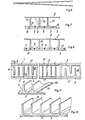
- Fig. 1 einen Querschnitt durch einen Heizungskessel allerdings nur beispielhafter Art ;
- Fig. 2 einen Blechzuschnitt für die U-Profile ;
- Fig. 3 einen Längsschnitt durch den Heizungskessel ;
- Fig. 4 im Schnit die U-Profile nach Anbringung auf dem noch planen, später das Rohr bildenden Blechzuschnitt ;
- Fig. 5 im Schnitt die U-Profile gemäß Fig. 4 nach ihrer Verformung ;
- Fig. 6 eine besondere Ausführungsform hinsichtlich der Zurichtung der U-Profile gemäß Fig. 5 in Draufsicht und
- Fig. 7-11 im Schnitt besondere und bevorzugte Ausführungsformen der Profile und ihrer gegenseitigen Zuordnung an allein oder beidseitig wasserführenden Zugwänden.
- Figure 1 shows a cross section through a heating boiler, however, only of an exemplary nature.
- 2 shows a sheet metal blank for the U-profiles;
- 3 shows a longitudinal section through the heating boiler.
- Fig. 4 in section the U-profiles after mounting on the still plan, later forming the tube sheet metal blank;
- 5 shows in section the U-profiles according to FIG. 4 after their deformation;
- Fig. 6 shows a special embodiment with regard to the preparation of the U-profiles according to FIG. 5 in plan view and
- Fig. 7-11 in section special and preferred embodiments of the profiles and their mutual assignment on water conductors alone or on both sides.
Der Heizungskessel gemäß Fig. 3 ist nur ein Beispiel und besteht in an sich bekannter Weise aus einem wasserführenden Gehäuse 22, dessen Vorder- und Rückwand 23, 24 flüssigkeitsdicht von der rohrförmigen Wand 3 durchgriffen werden, wobei die überstehenden Enden mit Deckeln oder Türen verschlossen sind. Der hintere Deckel 25 ist mit einem Rauchgasabzugstutzen 26 versehen. Im von der Wand gebildeten Rohr ist brennerseitig (Brenner nicht dargestellt) die Umlenkkammer 27 angeordnet. Im Freiraum zwischen den Heizgaszügen 8 sitzt die topfartige Brennkammer 28, und dahinter befindet sich die Rauchgassammelkammer 28'. Dieser Kesselaufbau ist nicht unbedingt zwingend, genausowenig wie die Brennkammer 28 zylindrisch sein muß und die Heizgaszüge 8 im Ringverband angeordnet sein müssen. Ggf. können hinter der Brennkammer 28 bzw. den Heizgaszügen 8 zusätzliche Nachsschaltheizflächen angeordnet werden. Ferner können auch die Wände der Brennkammer als wasserführende Doppelwände ausgebildet sein, deren Innenraum mit dem anderen Innenraum des Gehäuses 22 in geeigneter Weise verbunden ist. Dies wäre der Fall, bei dem die Heizgaszüge 8 beidseitig von wassergekühlten Wänden 3, 3' begrenzt werden.3 is only an example and consists in a manner known per se of a water-carrying
Die Blechzuschnitte für die Rippenprofile 1 sehen vor der Verformung zu U-Profilen so aus, wie aus Fig. 2 erkennbar. Die seitlichen Schlitze dienen zum Ausgleich von Wärmedehnungen, sind aber nicht unbedingt erforderlich.The sheet metal blanks for the rib profiles 1 look like they can be seen in FIG. 2 before they are deformed into U-profiles. The side slots are used to compensate for thermal expansion, but are not absolutely necessary.
Nach Hochkanten der die freien Schenkel 29 bildenden Flächen werden die so gebildeten Profile im Sinne der Fig. 4 auf die später das Rohr bildende, noch planen oder schwach vorgewölbten Blechzuschnitte der Wand 3 dicht nebeneinander aufgelegt und im Bereich der Längsschweißschlitze 16 mit der Wand verschweißt. Wie aus Fig. 2 erkennbar, nimmt die Länge dieser Schlitze 26 nach hinten ab, während ihre Distanz zueinander zunimmt, d. h. es entstehen in Verbindung mit dem Blechzuschnitt Wärmeleitbrücken 5 unterschiedlicher Größe. Dies gilt auch für alle noch nachfolgend zu beschreibenden Ausführungsbeispiele. Nun wird zwischen die freien Schenkel 9 jeweils zweier benachbarter Profile 1 ein keilförmiges Werkzeug (als Dreieck vereinfacht in Fig. 4 dargestellt) eingedrückt, so daß sich danach die Profile im Querschnitt, wie aus Fig. 5 bzw. Fig. 1 ersichtlich, darstellen. Ggf. können in den sich bildenden Zwickeln 30' (Fig. 5) zusätzlich Längsschweißnähte verlegt werden. Ferner ist es möglich, die Abwinkelung der Schenkel im Sinne der Fig. 6 vorzunehmen.After the edges of the surfaces forming the
Vorteilhaft kann am hinteren Ende des Rohres eine ringförmige Schale 30 entweder ganz oder, wie dargestellt, zum Teil frei herausragend im Bereich der Rauchgassammelkammer 28' angeordnet werden, für die aber wesentlich ist, daß diese mit ihrem inneren Rand mit den Profilen 1 verschweißt sind, um einen Wärmezufluß aus den Profilen in die Schale 30 zu gewährleisten, so daß sich auch diese schnell aufheizen kann.At the rear end of the tube, an
Unter der Angabe « in Teilbereichen wärmeleitend verbunden » ist einmal die vorbeschriebene Schlitzschweißverbindung zu verstehen, zum anderen ist es aber auch möglich, und dies wird auch wegen des wesentlich geringeren Aufwandes bevorzugt, die Basisstege 2 mit bspw. einer Wolframelektrode (d. h. ohne Zufuhr von Zusatzschweißwerkstoff) anzuschweißen bzw. anzuschmelzen. Die Anbringung von Längsschweißschlitzen 16 unterschiedlicher Größe und Distanz kann dabei entfallen, und die Anheftung geschieht dabei in der Weise, daß der Heftbereich bzw. die sich ergebende Wärmeleitbrücke 5 von vorn nach hinten schmaler bzw. geringer wird. Dies läßt sich ohne weiteres und einfach durch entsprechend geregelte Stromzufuhr zur Elektrode bewerkstelligen, wobei die Schweiß- bzw. Heftnaht im Sinne der unterschiedlichen Distanzen der Schlitze gemäß Fig. 2 unterbrochen, ist.The term "thermally connected in some areas" is to be understood as the slot welding connection described above, but it is also possible, and this is also preferred because of the much lower expenditure, that the
Bei der Ausführungsform nach Fig. 7 sind die im Querschnitt U-förmigen Strömungskanäle des Heizgaszuges durch rechtwinklige Profile 10 gebildet, d. h. zwei benachbarte Profile 10 begrenzen einen Einzelkanal. Gleiches gilt für die T-förmigen Profile 11 gemäß Fig. 11. Wie aus Fig. 8 ersichtlich, können aber auch U-Profile mit Abstand zueinander angeordnet werden, wobei die freibleibenden Flächen der Wand 3 mit entsprechend breiten Zwischenstegen 12 abgedeckt werden, um das Doppelwandprinzip in allen Flächenbereichen aufrechtzuerhalten. Bei den Profilen gemäß Fig. 7, 8 werden vorteilhaft beim Pressen der Profile in den Übergangsbereichen 13 der Schenkel 9 zu den Stegen 2 Profilkröpfungen 14 vorgesehen, die zur Aufnahme der Anschlußränder 15 benachbart angeordneter Stege 2 bzw. der Zwischenstege 12 dienen. Dies ist vorteilhaft, um ein Hochwölben beim Schweißen der Stege 2 bzw. der Zwischenstege 12 zu verhindern.In the embodiment according to FIG. 7, the flow channels of the heating gas flue which are U-shaped in cross section are formed by
Die Schenkel 9 der Profile 10, 11, die die Längsrippen 1 bilden können, wie in Fig. 7 angedeutet, in Abständen mit fahnenartigen Ausbiegungen 19 versehen werden. Mit 3" ist in diesen Fig. 7, 8 übrigens die Wand der in diesem Fall nicht wassergekühlten Brennkammer 28 bezeichnet.The
Wenn die Brennkammer im Gegensatz zu Fig. 3 wassergekühlt ist, so liegt (derartige Kessel sind bekannt) in bezug auf den Heizgaszug eine zusätzliche wassergekühlte Wand 3' vor, die ebenfalls mit den beschriebenen Profilen nach dem gleichen Prinzip besetzt sind (Fig. 9). Je nach freiem Querschnitt eines derartigen Zuges und je nach Länge der Schenkel 9 kann die Anordnung derart erfolgen, daß die Längsränder 17 der sich gegenüberstehenden Profile 10, 11 etwa in der gleichen Zwischenebene enden oder etwas in den Zwischenraum 18 der jeweils anderen Profile einragen. Vorteilhaft wird jedoch eine Anordnung gemäß Fig. 9 derart gewählt, daß die Längsränder 17 dicht über den geschweißten Stellen der Wärmeleitbrücke 5 verlaufen. Da sich diese Längsränder 17 beim Wiederanfahren bzw. generell beim Betrieb im Niedertemperaturbereich des Kessels sehr schnell aufheizen, jedenfalls wesentlich schneller als die der Kühlung unterliegenden Wärmeleitbrücken, kann sich die Aufheizung der Längsränder 17 via Strahlung auch auf etwa an den Wärmeleitbrücken gebildetes Kondensat auswirken, so daß dieses schneller verdampft.If, in contrast to FIG. 3, the combustion chamber is water-cooled, there is (such boilers are known) an additional water-cooled wall 3 'with respect to the heating gas flue, which are also covered with the profiles described according to the same principle (FIG. 9) . Depending on the free cross section of such a train and depending on the length of the
Wie aus Fig. 10 erkennbar, können auch mehrere Schenkel 9 einen gemeinsamen Steg 2 haben und das ganze Profil bspw. auch als Strangpreßprofil mit geeigneter Wandstärke ausgebildet sein.As can be seen from FIG. 10,
In den Fig. 7 bis 11 sind die Heizgaszüge in gerader Erstreckung dargestellt, die je nach den konstruktiven Gegebenheiten am Heizkessel selbstverständlich auch in dieser Form zur Anwendung kommen kann. Es sei aber darauf hingewiesen, daß Züge in dieser Ausbildung orientiert an modernen Heizkesselkonstruktionen in der Regel mehr oder weniger stark gekrümmte Wände 3 bzw. 3' aufweisen, d. h., die gezeigten Ausführungsbeispiele gelten auch für solche gekrümmten Flächen. Wesentlicher Gesichtspunkt bei der ganzen Heizgaszugausbildung ist also, wie beschrieben, zusammenfassend gewissermaßen eine Trockenlegung heizgasführender Bereiche dahingehend, daß weitgehend eine Kondensatbildung verhindert wird, andererseits aber dafür gesorgt, daß etwaige Kondensatniederschläge beim Wiederanlaufen des Kessels schnellstmöglich verdampft werden. Mit derartigen Zugausbildungen versehene und über längere Zeitspanne betriebene Versuchskessel haben gezeigt, daß diese Forderungen absolut zufriedenstellend erfüllt werden.7 to 11, the heating gas flues are shown in a straight extension, which of course can also be used in this form depending on the structural conditions on the boiler. It should be noted, however, that trains in this design, based on modern boiler designs, generally have more or less
Claims (8)
Priority Applications (1)
| Application Number | Priority Date | Filing Date | Title |
|---|---|---|---|
| AT84102993T ATE38091T1 (en) | 1983-03-21 | 1984-03-19 | HEATING GAS TRAINING ON BOILERS. |
Applications Claiming Priority (2)
| Application Number | Priority Date | Filing Date | Title |
|---|---|---|---|
| DE3310072 | 1983-03-21 | ||
| DE3310072A DE3310072C2 (en) | 1983-03-21 | 1983-03-21 | Heating gas flue training on heating boilers |
Publications (3)
| Publication Number | Publication Date |
|---|---|
| EP0120435A2 EP0120435A2 (en) | 1984-10-03 |
| EP0120435A3 EP0120435A3 (en) | 1986-01-22 |
| EP0120435B1 true EP0120435B1 (en) | 1988-10-19 |
Family
ID=6194097
Family Applications (1)
| Application Number | Title | Priority Date | Filing Date |
|---|---|---|---|
| EP84102993A Expired EP0120435B1 (en) | 1983-03-21 | 1984-03-19 | Shape of fuel gas passages in boilers |
Country Status (3)
| Country | Link |
|---|---|
| EP (1) | EP0120435B1 (en) |
| AT (1) | ATE38091T1 (en) |
| DE (2) | DE3310072C2 (en) |
Families Citing this family (4)
| Publication number | Priority date | Publication date | Assignee | Title |
|---|---|---|---|---|
| DE3535341A1 (en) * | 1985-10-03 | 1987-04-09 | Viessmann Hans | BOILER FOR LIQUID OR GASEOUS FUELS |
| AT399571B (en) * | 1992-02-21 | 1995-06-26 | Windhager Ohg Anton | Low-temperature heating boiler for hot-water central heating systems and the like |
| DE4400400A1 (en) * | 1994-01-08 | 1995-07-13 | Viessmann Werke Kg | Three-pass boiler |
| DE19622567A1 (en) * | 1996-06-05 | 1997-12-11 | Stahl Und Apparatebau Josef Sc | Heating boiler insert for ribbed circular combustion chamber |
Family Cites Families (6)
| Publication number | Priority date | Publication date | Assignee | Title |
|---|---|---|---|---|
| DE1501676A1 (en) * | 1966-09-05 | 1969-10-23 | Variotherm S A | Inner finned tube for pressurized gas or pressurized oil heated boilers, especially of collective heating systems |
| DE1778832A1 (en) * | 1968-06-11 | 1971-08-26 | Thyssen Industrie | Hot water boilers, in particular heating boilers |
| DE2852650A1 (en) * | 1978-12-06 | 1980-07-17 | Interliz Anstalt | Oil or gas fired boiler - has hollow triangular sections in annular flue joined to outside wall |
| DE2856338B2 (en) * | 1978-12-27 | 1981-01-22 | Hans 3559 Battenberg Viessmann | Heating boilers for liquid or gaseous fuels |
| DE2948864C2 (en) * | 1979-12-05 | 1982-10-14 | Hans 3559 Battenberg Vießmann | Heating boilers for the combustion of liquid or gaseous fuels |
| DE3225762A1 (en) * | 1982-07-09 | 1984-01-12 | Hans Dr.h.c. 3559 Battenberg Vießmann | Heating boiler |
-
1983
- 1983-03-21 DE DE3310072A patent/DE3310072C2/en not_active Expired
-
1984
- 1984-03-19 AT AT84102993T patent/ATE38091T1/en active
- 1984-03-19 EP EP84102993A patent/EP0120435B1/en not_active Expired
- 1984-03-19 DE DE8484102993T patent/DE3474716D1/en not_active Expired
Also Published As
| Publication number | Publication date |
|---|---|
| ATE38091T1 (en) | 1988-11-15 |
| EP0120435A2 (en) | 1984-10-03 |
| DE3310072C2 (en) | 1986-12-18 |
| DE3310072A1 (en) | 1984-10-04 |
| DE3474716D1 (en) | 1988-11-24 |
| EP0120435A3 (en) | 1986-01-22 |
Similar Documents
| Publication | Publication Date | Title |
|---|---|---|
| DE3007867A1 (en) | CATALYTIC CONVERTER FOR ENGINE EXHAUST GASES | |
| DE2613186C3 (en) | Heating boilers for liquid or gaseous fuels | |
| EP0576963A1 (en) | Residual heat exchanger for mounting in the boiler casing | |
| EP0120435B1 (en) | Shape of fuel gas passages in boilers | |
| DE4232880A1 (en) | Fossil-fuelled steam-generator - has tubes forming flue walls joined together gas-tight at bottom and leaving intervening gaps further up | |
| DE3205121C2 (en) | Heating boiler | |
| EP0706010B1 (en) | Heating appliance having a nozzle assembly | |
| DE3205122C2 (en) | Heating boiler | |
| DE3225762C2 (en) | ||
| EP0168637A2 (en) | Gas-fired heater, especially a condensing heater, with a spirally formed smoke duct, method for making such a heater and heater made by such a method | |
| EP0387627B1 (en) | Heater | |
| EP0503146B1 (en) | Flat heating gas draft tube especially for condensing boiler | |
| DE4107948C1 (en) | Heating gas flue pocket of two sheet metal blanks - top, conically tapering inlet duct, and conically widening, lower outlet duct | |
| EP0387628B1 (en) | Heater | |
| EP0430061B1 (en) | Boiler | |
| DE4229146C1 (en) | Gas boiler | |
| EP0583574B1 (en) | Gas-fired boiler | |
| EP0680586A1 (en) | Heating boiler | |
| EP0662592B1 (en) | Three-pass boiler | |
| DE7136314U (en) | Heating boiler | |
| DE3310098A1 (en) | Heating boiler | |
| DE102009050517A1 (en) | Burning grill kit | |
| DE3205119A1 (en) | Heating boiler for liquid or gaseous fuels | |
| DE8308336U1 (en) | HEATING BOILER | |
| CH677199A5 (en) | Sheet metal flue liner |
Legal Events
| Date | Code | Title | Description |
|---|---|---|---|
| PUAI | Public reference made under article 153(3) epc to a published international application that has entered the european phase |
Free format text: ORIGINAL CODE: 0009012 |
|
| AK | Designated contracting states |
Designated state(s): AT BE CH DE FR GB IT LI LU NL SE |
|
| PUAL | Search report despatched |
Free format text: ORIGINAL CODE: 0009013 |
|
| AK | Designated contracting states |
Designated state(s): AT BE CH DE FR GB IT LI LU NL SE |
|
| 17P | Request for examination filed |
Effective date: 19860715 |
|
| 17Q | First examination report despatched |
Effective date: 19861209 |
|
| GRAA | (expected) grant |
Free format text: ORIGINAL CODE: 0009210 |
|
| AK | Designated contracting states |
Kind code of ref document: B1 Designated state(s): AT BE CH DE FR GB IT LI LU NL SE |
|
| PG25 | Lapsed in a contracting state [announced via postgrant information from national office to epo] |
Ref country code: GB Free format text: LAPSE BECAUSE OF NON-PAYMENT OF DUE FEES Effective date: 19881019 |
|
| REF | Corresponds to: |
Ref document number: 38091 Country of ref document: AT Date of ref document: 19881115 Kind code of ref document: T |
|
| REF | Corresponds to: |
Ref document number: 3474716 Country of ref document: DE Date of ref document: 19881124 |
|
| ET | Fr: translation filed | ||
| ITF | It: translation for a ep patent filed |
Owner name: MODIANO & ASSOCIATI S.R.L. |
|
| PG25 | Lapsed in a contracting state [announced via postgrant information from national office to epo] |
Ref country code: LU Free format text: LAPSE BECAUSE OF NON-PAYMENT OF DUE FEES Effective date: 19890331 |
|
| GBV | Gb: ep patent (uk) treated as always having been void in accordance with gb section 77(7)/1977 [no translation filed] | ||
| PLBE | No opposition filed within time limit |
Free format text: ORIGINAL CODE: 0009261 |
|
| STAA | Information on the status of an ep patent application or granted ep patent |
Free format text: STATUS: NO OPPOSITION FILED WITHIN TIME LIMIT |
|
| 26N | No opposition filed | ||
| PG25 | Lapsed in a contracting state [announced via postgrant information from national office to epo] |
Ref country code: DE Effective date: 19891201 |
|
| ITTA | It: last paid annual fee | ||
| EAL | Se: european patent in force in sweden |
Ref document number: 84102993.7 |
|
| PGFP | Annual fee paid to national office [announced via postgrant information from national office to epo] |
Ref country code: BE Payment date: 19990303 Year of fee payment: 16 |
|
| PGFP | Annual fee paid to national office [announced via postgrant information from national office to epo] |
Ref country code: SE Payment date: 19990305 Year of fee payment: 16 |
|
| PGFP | Annual fee paid to national office [announced via postgrant information from national office to epo] |
Ref country code: CH Payment date: 19990326 Year of fee payment: 16 |
|
| PGFP | Annual fee paid to national office [announced via postgrant information from national office to epo] |
Ref country code: NL Payment date: 19990331 Year of fee payment: 16 Ref country code: FR Payment date: 19990331 Year of fee payment: 16 Ref country code: AT Payment date: 19990331 Year of fee payment: 16 |
|
| PG25 | Lapsed in a contracting state [announced via postgrant information from national office to epo] |
Ref country code: AT Free format text: LAPSE BECAUSE OF NON-PAYMENT OF DUE FEES Effective date: 20000319 |
|
| PG25 | Lapsed in a contracting state [announced via postgrant information from national office to epo] |
Ref country code: SE Free format text: LAPSE BECAUSE OF NON-PAYMENT OF DUE FEES Effective date: 20000320 |
|
| PG25 | Lapsed in a contracting state [announced via postgrant information from national office to epo] |
Ref country code: LI Free format text: LAPSE BECAUSE OF NON-PAYMENT OF DUE FEES Effective date: 20000331 Ref country code: CH Free format text: LAPSE BECAUSE OF NON-PAYMENT OF DUE FEES Effective date: 20000331 Ref country code: BE Free format text: LAPSE BECAUSE OF NON-PAYMENT OF DUE FEES Effective date: 20000331 |
|
| BERE | Be: lapsed |
Owner name: VIESSMANN HANS Effective date: 20000331 |
|
| PG25 | Lapsed in a contracting state [announced via postgrant information from national office to epo] |
Ref country code: NL Free format text: LAPSE BECAUSE OF NON-PAYMENT OF DUE FEES Effective date: 20001001 |
|
| EUG | Se: european patent has lapsed |
Ref document number: 84102993.7 |
|
| REG | Reference to a national code |
Ref country code: CH Ref legal event code: PL |
|
| PG25 | Lapsed in a contracting state [announced via postgrant information from national office to epo] |
Ref country code: FR Free format text: LAPSE BECAUSE OF NON-PAYMENT OF DUE FEES Effective date: 20001130 |
|
| NLV4 | Nl: lapsed or anulled due to non-payment of the annual fee |
Effective date: 20001001 |
|
| REG | Reference to a national code |
Ref country code: FR Ref legal event code: ST |