EP0583546A1 - Handling truck, in particular driverless vehicle - Google Patents
Handling truck, in particular driverless vehicle Download PDFInfo
- Publication number
- EP0583546A1 EP0583546A1 EP93106034A EP93106034A EP0583546A1 EP 0583546 A1 EP0583546 A1 EP 0583546A1 EP 93106034 A EP93106034 A EP 93106034A EP 93106034 A EP93106034 A EP 93106034A EP 0583546 A1 EP0583546 A1 EP 0583546A1
- Authority
- EP
- European Patent Office
- Prior art keywords
- cylinder
- drive wheel
- industrial truck
- truck according
- valve
- Prior art date
- Legal status (The legal status is an assumption and is not a legal conclusion. Google has not performed a legal analysis and makes no representation as to the accuracy of the status listed.)
- Withdrawn
Links
Images


Classifications
-
- B—PERFORMING OPERATIONS; TRANSPORTING
- B62—LAND VEHICLES FOR TRAVELLING OTHERWISE THAN ON RAILS
- B62B—HAND-PROPELLED VEHICLES, e.g. HAND CARTS OR PERAMBULATORS; SLEDGES
- B62B3/00—Hand carts having more than one axis carrying transport wheels; Steering devices therefor; Equipment therefor
- B62B3/04—Hand carts having more than one axis carrying transport wheels; Steering devices therefor; Equipment therefor involving means for grappling or securing in place objects to be carried; Loading or unloading equipment
- B62B3/06—Hand carts having more than one axis carrying transport wheels; Steering devices therefor; Equipment therefor involving means for grappling or securing in place objects to be carried; Loading or unloading equipment for simply clearing the load from the ground
- B62B3/0625—Hand carts having more than one axis carrying transport wheels; Steering devices therefor; Equipment therefor involving means for grappling or securing in place objects to be carried; Loading or unloading equipment for simply clearing the load from the ground using rigid mechanical lifting mechanisms, e.g. levers, cams or gears
-
- B—PERFORMING OPERATIONS; TRANSPORTING
- B60—VEHICLES IN GENERAL
- B60G—VEHICLE SUSPENSION ARRANGEMENTS
- B60G17/00—Resilient suspensions having means for adjusting the spring or vibration-damper characteristics, for regulating the distance between a supporting surface and a sprung part of vehicle or for locking suspension during use to meet varying vehicular or surface conditions, e.g. due to speed or load
- B60G17/02—Spring characteristics, e.g. mechanical springs and mechanical adjusting means
- B60G17/027—Mechanical springs regulated by fluid means
-
- B—PERFORMING OPERATIONS; TRANSPORTING
- B66—HOISTING; LIFTING; HAULING
- B66F—HOISTING, LIFTING, HAULING OR PUSHING, NOT OTHERWISE PROVIDED FOR, e.g. DEVICES WHICH APPLY A LIFTING OR PUSHING FORCE DIRECTLY TO THE SURFACE OF A LOAD
- B66F9/00—Devices for lifting or lowering bulky or heavy goods for loading or unloading purposes
- B66F9/06—Devices for lifting or lowering bulky or heavy goods for loading or unloading purposes movable, with their loads, on wheels or the like, e.g. fork-lift trucks
- B66F9/075—Constructional features or details
- B66F9/07586—Suspension or mounting of wheels on chassis
-
- B—PERFORMING OPERATIONS; TRANSPORTING
- B60—VEHICLES IN GENERAL
- B60G—VEHICLE SUSPENSION ARRANGEMENTS
- B60G2300/00—Indexing codes relating to the type of vehicle
- B60G2300/02—Trucks; Load vehicles
- B60G2300/022—Fork lift trucks, Clark
Definitions
- the invention relates to an industrial truck, in particular driverless vehicle, according to the preamble of patent claim 1.
- the precautions described therefore enable an optimal wheel load on the drive wheels. Their traction and braking ability is matched to the respective load, so that slipping or blocking of the drive wheels is avoided.
- the stopping distances that can be achieved in the event of braking are relatively short. Under certain circumstances, an increased steering force at higher loads has to be accepted if steering assistance is not provided.
- Driverless transport vehicles are often equipped with two steerable drive wheels. If the drive wheels have a different orientation from the support rollers and, as is usually the case, the support rollers are designed as swivel rollers, there is an even higher required driving force, in particular when changing the direction of travel, for example in order to overcome the swivel resistance of the support rollers.
- the vehicle may also break away to the side.
- the invention has for its object to provide an industrial truck, in particular driverless vehicle, which can be easily manipulated even if functions fail.
- a double-acting hydraulic cylinder which, when loaded in one direction, the spring preload on the drive wheel raised and when driving in the opposite direction, the drive wheel lifts off the ground.
- the hydraulic cylinder is expediently arranged such that it increases the spring preload when there is pressure in the upper cylinder chamber and that the drive wheel lifts off the ground when the lower cylinder chamber is pressurized.
- both cylinder spaces are connected to the lifting cylinder arrangement on both sides of the piston.
- a one-sided connection of the biasing cylinder is already known, as stated above.
- the pressure force cannot be arbitrarily high, because on the one hand the support rollers are relieved too much and on the other hand the wheel pressure would become too great.
- a corresponding limitation can be made by means of stops.
- the double-acting hydraulic cylinder in the desired manner and letting it act.
- the cylinder is attached to the chassis at one end and its piston rod has two stops at a distance from one another
- the spring arrangement is arranged between the vertically movable support of the drive wheel and a height-adjustable abutment component which is in the upper position supported on the chassis and lifted off the chassis when the cylinder is adjusted in the first direction of action and the first stop interacts with the abutment component and the second stop raises the carrier when the cylinder is adjusted in the second direction of action.
- the carrier for example in the form of a plate, is preferably designed as a rocker arm, as is known per se, which is mounted on the chassis so as to be pivotable about a horizontal axis. Since the rocker arm describes a small circular arc in the area of attack of the piston rod, it is expedient if the double-acting hydraulic cylinder is pivotably pivoted on the chassis.
- the plane in which the springs are arranged preferably extends parallel to the vertical plane through the pivot axis of the rocker.
- an embodiment of the invention provides that the outlet of the pump can be connected to the cylinder chamber determining the second direction of action via a shut-off valve. If, however, the hydraulic pump has failed, one embodiment of the invention provides that the cylinder space determining the second direction of action is connected to a coupling for connecting an external hydraulic pump.
- the external hydraulic pump can be a hand pump with a tank.
- hydraulic supports can be used for this purpose, which can be connected to the outlet of the pump via a control switching valve.
- a switching valve for the double-acting hydraulic cylinder is connected to the outputs of the control switching valve such that the drive wheel is raised when the supports are lowered and when the supports are raised the drive wheel is lowered when both switching valves are in a predetermined switching position. So that the functions described can still be performed in the event of a fault, all valves for the hydraulic circuit can be operated manually.
- actuation via an external pump is expediently also provided for the hydraulic drive of the supports, should it e.g. malfunction if they are just extended.
- the vehicle can only be towed if the supports are also raised.
- a driverless fork lift 10 according to FIG. 1 has four Support rollers 12, 14, 16, 18 and an intermediate drive wheel 20.
- the support rollers 12, 14 are designed as swivel rollers.
- a collision protection 26 is arranged at the end opposite the forks 22, 24, arranged.
- the vehicle 10a according to FIG. 2 also contains hydraulic supports 28, 30, 32, 34 on each outer side. As can be seen from FIG. 3, the load-carrying means 36 of the vehicle 10a can also move a load 38 cantilevered to the side. For better stabilization of the vehicle 10a, the hydraulic supports 28 to 34 are extended, so that the tipping edge of the vehicle 10a lies on the outside.
- the drive wheels 20a, 20b are adjusted to a raised position.
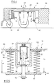
- the drive wheel 20 is attached to a rocker 40 which is pivotally mounted at 42 about a horizontal axis.
- a wheel hub gear 44, on which the drive wheel 20 is mounted, is with Using a roller bearing 46 rotatable about a vertical axis 48. The twisting is done for steering purposes.
- the drive for the drive wheel 20 and the brake are not shown. They are traditional.
- the rocker 40 is supported by two springs 50, 52 on an outwardly facing flange 54 of an abutment component 56 guided by guides 51, 53 on the chassis 66.
- the abutment component 56 surrounds a double-acting hydraulic cylinder 58 with a piston 60 and a piston rod 62.
- the hydraulic cylinder 58 is articulated at 64 to the chassis 66 of the vehicle 10.
- the piston rod 62 passes through an opening of the abutment component 56 and has a first stop 68 which interacts with the associated section of the abutment component 56 when the piston rod 62 is moved downward.
- the piston rod 62 also passes through an opening of the rocker 40 and at the end has a second stop 70 which cooperates with the rocker 40 when the piston rod 62 moves upwards.
- the suspension of the drive wheel 20 enables a vertical movement of the rocker 40 of ⁇ a to compensate for uneven floors.
- the control of the hydraulic cylinder 58 can be seen in FIG. 8. 5, flange 54 abuts the bottom of chassis section 66 and springs 50, 52 are at their maximum Expansion L F1 .
- the distance of the rocker 40 from the chassis 66 is designated L1.
- the vehicle 10 according to FIG. 1 has a lifting cylinder 72 for lifting a load handler, for example a fork. 3 can be actuated by the lifting cylinder 72.
- a hydraulic motor-driven pump 74 with tank 76 supplies the lifting cylinder 72 via a switching valve 78.
- the two-way valve 78 optionally enables the lifting cylinder 72 to be connected to the pump 74 or the tank 76.
- a pressure relief valve 78 ′ enables the delivery medium to be discharged to the tank 76 high pressure.
- the outlet of the pump 74 is connected to the lower cylinder space of the cylinder 58 via a line 80 with a shut-off valve 82.
- the lower cylinder chamber is connected via a line 84 with shut-off valve 86 to the upper cylinder chamber, which is also connected via a line 88 to the lifting cylinder 72.
- a spring-loaded, hydraulically reinforced brake device 90 which is electromagnetically released, is connected via a line 92 to line 88, so that the preload of the brake 90 is dependent on the pressure in the hydraulic cylinder 72.
- a coupling part 94 is provided on the vehicle for connection a line 96 of a hand pump 98.
- the external hand pump 98 can optionally be connected.
- the operation of the hydraulic cylinder 58 in the event of a failure is considered below for two different cases.
- the energy supply and the hydraulic pump 74 are ready for operation.
- the pump 74 and the energy supply are no longer ready for operation.
- the shut-off valve 82 is opened, the shut-off valve 86 is closed, the directional control valve 78 is actuated electromagnetically and the pump 74 is switched on.
- the lifting cylinder 72 lowers and the annular space of the hydraulic cylinder 58 is supplied with oil.
- the piston 60 or the piston rod 62 is moved upward, as a result of which the abutment component can bear against the chassis 66 due to the spring force of the springs 50, 52.
- the stop 70 comes into engagement with the rocker 40, so that the drive wheel 20 is lifted off the ground.
- L F and L1 are reduced to L F3 and L3 when the piston 60 reaches the upper stop (see Fig. 7).
- the drive wheel is now without contact with the ground and that Vehicle can be moved or towed freely.
- the shut-off valve 82 is closed, the pump 74 is switched off and the directional valve 78 is brought into the zero position again. If the load is to remain on the vehicle during towing, the pump 74 is switched on until the transport height is reached.
- shut-off valves 82 and 86 are closed, the directional control valve 78 is actuated manually and the external hand pump 98 is connected via the coupling 94.
- the lifting cylinder 72 is lowered and the drive wheel 20 is raised by actuating the hand pump 98.
- the towing process can begin after the directional control valve 78 has been brought into the zero position again. If the load is to remain on the vehicle during the towing process, the load is raised by closing the shutoff valve 82, neutralizing the directional control valve 78, opening the shutoff valve 86 and actuating the hand pump 98.
- shut-off valve 86 is then closed and the piston rod 62 is retracted as far as possible by actuating the pump 98.
- the hydraulic medium displaced from the cylinder 58 flows into the lifting cylinder 72, which reduces the load slightly continues to rise.
- the drive wheel 20 is no longer in contact with the ground and the towing operation can be carried out with a raised load.
- shut-off device on the hand pump 98 is opened and the piston rod 62 extends until the drive wheel 20 is again on the ground.
- the load lowers slightly.
- the shut-off valve 86 is then opened and / or the valve 78 so that the load can be completely lowered by the hydraulic medium flowing back to the tank.
- the directional control valve 78 is not actuated, the pump 74 is out of operation, the shut-off valve 82 is closed, the shut-off valve 86 is open and the hand pump 98 is not connected.
- the lifting cylinder 72 is connected both to the annular space and to the other piston space of the hydraulic cylinder 58.
- the hydraulically assisted spring-applied brake 90 is also connected to the lifting cylinder 72. Due to the low pressure in the lifting cylinder 72 when the vehicle is unladen, there is neither an increase in the drive wheel load nor in the braking torque.
- the abutment component 56 bears against the chassis 66, and the springs 50, 52 have the installation length shown in FIG. 5.
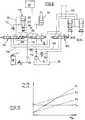
- the load on the drive wheel F N 'and the load F S ' on the support rollers at variable pressure are shown in dashed lines. It can be seen that as the preload on the drive wheel increases, as the load increases, the pressure on the support rollers also increases with increasing load, but not to the same extent as with a constant wheel load of the drive wheel.
- FIG. 6 shows how the preload on the rocker 40 and thus the wheel load on the drive wheel 20 is increased by extending the piston rod 62.
- the abutment component 56 moves away from the chassis 66 in the direction of the rocker 40, the maximum dimension being limited by the stop of the piston 60 in the cylinder.
- a directional valve 100 and a directional valve 102 are provided in addition to the directional valve 78 with the positions 0, 1 and 2, a directional valve 100 and a directional valve 102 are provided.
- position 1 of the directional control valve 100 the hydraulic supports 28, 30 and 32, 34 are actuated, as described in connection with FIG. 3. This is done, if necessary, by means of a level control 104 shown in broken lines.
- position 2 of the directional control valve 100 the supports 28 to 34 can be raised.
- the directional control valve 100 is connected via lines 106 and 108 to the input of the directional control valve 102, which can also assume positions 0, 1 and 2.
- both the drive wheel can be raised and the hydraulic supports 28 to 34 can be lowered at the same time.
- the tipping edge moves to the outside edge of the vehicle and the empty weight of the vehicle fully serves to compensate for the tipping moment of the laterally shifted load, without being reduced by spring forces.
- valve 100 By actuating the valve 100 in position 1 and switching on the pump 78, the supports 28 to 34 are extended to the stop. By actuating the valve 102 in the position 2, the drive wheel is raised, the shut-off valve 112 being opened. The valve 100 jumps to position 0 and the valve 102 is moved to position 1, in which the cylinder 58 is shut off. The valve 78 can now be used to actuate the lifting cylinder 72 in order to raise or lower a load.
- the supports 28 to 34 are retracted by actuating the valve 100, and the cylinder 58 drives the drive wheel by actuating valve 102 in position 2 against the floor again.
- all valves 100, 102 and 78 are in position 0 and the load-dependent amplification of the pressure of the drive wheel on the ground and the braking torque of the brake 90 described above take place.
- the shut-off valve 116 is opened and the shut-off valve 112 is closed.
- the pump 74 is then switched on.
- the hydraulic medium displaced in the cylinder 58 slightly raises the load via the lifting cylinder 72.
- the shut-off valve 116 is closed and the vehicle can be towed.
- the shut-off valve 112 is opened, the load falling slightly.
- the auxiliary or hand pump 98 to be connected at 94 can be used to raise the drive wheel when the vehicle is to be towed.
- the valve 112 is closed.
- the hydraulic medium displaced in the cylinder 58 enters the lifting cylinder 72, which slightly raises the load.
- supports 28, 30 or 32, 34 are extended in the event of a fault, they can also be raised with the pump 98.
- open valve 116 and move valve 100 to position 2.
- the valve 116 is to be closed and the valve 100 is to be placed in the neutral position, so that the drive wheel and supports remain in the raised position and allow easy towing.
Abstract
Description
Die Erfindung bezieht sich auf ein Flurförderzeug, insbesondere fahrerloses Fahrzeug nach dem Oberbegriff des Patentanspruchs 1.The invention relates to an industrial truck, in particular driverless vehicle, according to the preamble of
Flurförderzeuge stützen sich aus naheliegenden Gründen in der Regel auf ungefederten Rädern oder Rollen ab. Sie sind über mindestens ein Antriebsrad angetrieben, das außerdem Lenk- und Bremsfunktion übernimmt. In bestimmten Ausführungsformen ist das Antriebsrad zwischen den Stützrollen angeordnet. Zur Erzeugung und Aufrechterhaltung einer ausreichenden Bodenhaftung wird das Antriebsrad mit federnder Vorspannung gegen den Untergrund gedrückt. Aus EP-A-0 209 502 B1 ist bekannt geworden, die Vorspannung am Antriebsrad lastabhängig zu machen dergestalt, daß sie mit steigender Last erhöht wird. Das Antriebsrad ist mittels einer Parallelschwinge am Chassis aufgehängt; sie wird von zwei Federn vorgespannt, wobei eine Feder in ihrer Vorspannung mit Hilfe eines hydraulischen Vorspannzylinders verändert werden kann. Der Vorspannzylinder ist direkt mit dem Hubzylinder des Förderzeugs gekoppelt. Dadurch wird erreicht, daß auch bei höherer Last ausreichende Traktionskräfte auf den Untergrund übertragen werden, was gleichzeitig für eine gute Bodenhaftung zu Abbremszwecken dient.For obvious reasons, industrial trucks are usually supported on unsprung wheels or castors. They are driven by at least one drive wheel, which also takes over the steering and braking functions. In certain embodiments, the drive wheel is disposed between the support rollers. To generate and maintain sufficient traction, the drive wheel is pressed against the ground with a resilient preload. From EP-A-0 209 502 B1 has become known to make the preload on the drive wheel dependent on the load in such a way that it is increased with increasing load. The drive wheel is suspended from the chassis by means of a parallel rocker; it is preloaded by two springs, the spring preload of which can be changed with the aid of a hydraulic preload cylinder. The preload cylinder is directly coupled to the lifting cylinder of the truck. This ensures that sufficient traction forces are transmitted to the ground even at higher loads, which also serves for good grip for braking purposes.
Werden Fahrzeuge, die mit mittig angeordneten, federnd aufgehängten Antrieben ausgerüstet sind, zur seitlichen Lastaufnahme oder -abgabe eingesetzt, so erzeugen die Reaktionskräfte der Federn am Fahrzeugrahmen ein Kippmoment um die Kippkante, das wie das Kippmoment der außerhalb der Standbasis befindlichen Last dem Standmoment entgegengerichtet ist. Dies kann nur durch eine Erhöhung der Fahrzeugeigenmassen ausgeglichen werden, was einen höheren Energiebedarf zur Folge hat, da das Fahrzeugleergewicht in Relation zur Traglast und die Radlasten der ungefederten Rädern zunehmen.If vehicles that are equipped with centrally arranged, spring-suspended drives are used for lateral load absorption or delivery, the reaction forces of the springs on the vehicle frame generate a tipping moment around the tipping edge, which, like the tipping moment of the load outside the base, is opposite to the standing moment . This can only be compensated for by increasing the vehicle's own mass, which results in a higher energy requirement, since the vehicle's unladen weight increases in relation to the load and the wheel loads of the unsprung wheels.
Aus der genannten Druckschrift ist daher auch bereits bekannt geworden, die Vorspannung am Antriebsrad zu reduzieren, wenn das Lastaufnahmemittel eine bestimmte Höhe erreicht hat. Dadurch wird die Kippneigung des Förderfahrzeugs verringert, was ein Ein- und Ausstapeln in größerer Höhe erleichtert. Dabei wird in Kauf genommen, daß die Traktionskraft und die Bremskraft als übertragbare Umfangskraft des Antriebsrads auf den Untergrund ebenfalls verringert wird. Dieser Nachteil kann jedoch für diesen Betriebszustand hingenommen werden, da Flurförderzeuge mit angehobener Last selten mit hohen Geschwindigkeiten fahren.It is therefore already known from the cited publication to reduce the preload on the drive wheel when the load handler has reached a certain height. This reduces the tendency of the conveyor vehicle to tip over, which makes it easier to stack and unpack at a greater height. It is accepted that the traction force and the braking force as a transferable peripheral force of the drive wheel on the ground is also reduced. However, this disadvantage can be accepted for this operating state, since industrial trucks with a raised load rarely drive at high speeds.
Die beschriebenen Vorkehrungen ermöglichen mithin eine optimale Radlast an den Antriebsrädern. Ihre Traktions- und Bremsfähigkeit ist auf die jeweilige Last abgestimmt, so daß ein Durchrutschen oder Blockieren der Antriebsräder vermieden wird. Die erzielbaren Anhaltewege im Bremsfall sind relativ kurz. Dabei muß unter Umständen eine erhöhte Lenkkraft bei höheren Lasten in Kauf genommen werden, soweit eine Lenkunterstützung nicht vorgesehen ist.The precautions described therefore enable an optimal wheel load on the drive wheels. Their traction and braking ability is matched to the respective load, so that slipping or blocking of the drive wheels is avoided. The stopping distances that can be achieved in the event of braking are relatively short. Under certain circumstances, an increased steering force at higher loads has to be accepted if steering assistance is not provided.
Bei Störungen an derartigen Flurförderzeugen, insbesondere bei fahrerlosen Transportfahrzeugen, besteht die Forderung, diese rasch und mit geringem Aufwand und einem Minimum an Hilfsmitteln aus dem Fahrkurs zu entfernen, um die Behinderung anderer Fahrzeuge zu vermeiden. Das Abschleppen gestaltet sich um so schwieriger, wenn das Antriebsrad nicht gelenkt und/oder die Bremse nicht gelöst werden kann.In the event of malfunctions in such industrial trucks, in particular in driverless transport vehicles, there is a requirement to remove them from the driving course quickly and with little effort and with a minimum of aids in order to avoid obstructing other vehicles. Towing is all the more difficult if the drive wheel cannot be steered and / or the brake cannot be released.
Fahrerlose Transportfahrzeuge werden häufig mit zwei lenkbaren Antriebsrädern versehen. Haben die Antriebsräder eine von den Stützrollen abweichende Ausrichtung und sind, wie dies zumeist üblich ist, die Stützrollen als Schwenkrollen ausgebildet, ergibt sich insbesondere bei Fahrtrichtungswechsel eine noch höhere erforderliche Antriebskraft, beispielsweise um den Schwenkwiderstand der Stützrollen zu überwinden. Es kann dabei auch zu einem seitlichen Ausbrechen des Fahrzeugs kommen.Driverless transport vehicles are often equipped with two steerable drive wheels. If the drive wheels have a different orientation from the support rollers and, as is usually the case, the support rollers are designed as swivel rollers, there is an even higher required driving force, in particular when changing the direction of travel, for example in order to overcome the swivel resistance of the support rollers. The vehicle may also break away to the side.
Der Erfindung liegt die Aufgabe zugrunde, ein Flurförderzeug, insbesondere fahrerloses Fahrzeug zu schaffen, das auch bei Ausfall von Funktionen noch einfach manipuliert werden kann.The invention has for its object to provide an industrial truck, in particular driverless vehicle, which can be easily manipulated even if functions fail.
Diese Aufgabe wird erfindungsgemäß gelöst durch die Merkmale des Patentanspruchs 1.This object is achieved according to the invention by the features of
Bei dem erfindungsgemäßen Flurförderzeug ist ein doppelt wirkender Hydraulikzylinder vorgesehen, der bei Beaufschlagung in einer Richtung die Federvorspannung am Antriebsrad erhöht und bei Beaufschlagung in entgegengesetzter Richtung das Antriebsrad vom Untergrund abhebt. Zweckmäßigerweise ist dabei der Hydraulikzylinder so angeordnet, daß er bei Druck im oberen Zylinderraum die Federvorspannung erhöht und bei Druckbeaufschlagung des unteren Zylinderraums das Antriebsrad vom Untergrund abhebt. Es hängt jedoch letztlich von der Kinematik der Aufhängung des Antriebsrades und der Anordnung des Hydraulikzylinders ab, welcher Zylinderraum des Hydraulikzylinders mit Druck versorgt werden muß, um die gewünschte Funktion zu erhalten. In jedem Fall ist es bei dem erfindungsgemäßen Flurförderzeug jederzeit möglich, die Andruckkraft des Antriebsrades zu reduzieren oder völlig aufzuheben, um ein funktionsgestörtes Förderzeug aus dem Fahrkurs zu entfernen, beispielsweise durch Abschleppen, Verschieben oder dergleichen.In the industrial truck according to the invention, a double-acting hydraulic cylinder is provided which, when loaded in one direction, the spring preload on the drive wheel raised and when driving in the opposite direction, the drive wheel lifts off the ground. The hydraulic cylinder is expediently arranged such that it increases the spring preload when there is pressure in the upper cylinder chamber and that the drive wheel lifts off the ground when the lower cylinder chamber is pressurized. However, it ultimately depends on the kinematics of the suspension of the drive wheel and the arrangement of the hydraulic cylinder, which cylinder chamber of the hydraulic cylinder must be supplied with pressure in order to achieve the desired function. In any case, with the industrial truck according to the invention it is possible at any time to reduce the pressure of the drive wheel or to cancel it completely in order to remove a malfunctioning conveyor from the driving course, for example by towing, moving or the like.
Bei einer Ausgestaltung der Erfindung sind beide Zylinderräume beidseits des Kolbens mit der Hubzylinderanordnung verbunden. Eine einseitige Verbindung des Vorspannzylinders ist, wie oben ausgeführt, bereits bekannt. Die Andruckkraft kann aus verständlichen Gründen nicht beliebig hoch sein, da zum einen eine zu starke Entlastung der Stützrollen auftreten und zum anderen der Raddruck zu groß werden würde. Es kann eine entsprechende Begrenzung mittels Anschlägen vorgenommen werden.In one embodiment of the invention, both cylinder spaces are connected to the lifting cylinder arrangement on both sides of the piston. A one-sided connection of the biasing cylinder is already known, as stated above. For understandable reasons, the pressure force cannot be arbitrarily high, because on the one hand the support rollers are relieved too much and on the other hand the wheel pressure would become too great. A corresponding limitation can be made by means of stops.
Es sind verschiedene konstruktive Lösungen denkbar, den doppelt wirkenden Hydraulikzylinder in gewünschter Weise anzuordnen und wirken zu lassen. Eine besteht erfindungsgemäß darin, daß der Zylinder an einem Ende am Chassis angebracht ist und seine Kolbenstange zwei Anschläge im Abstand voneinander aufweist, die Federanordnung zwischen dem höhenbeweglichen Träger des Antriebsrades und einem in der Höhe verstellbar geführten Widerlagerbauteil angeordnet ist, das sich in der oberen Position am Chassis abstützt und vom Chassis abhebt, wenn der Zylinder in der ersten Wirkungsrichtung verstellt wird und der erste Anschlag mit dem Widerlagerbauteil zusammenwirkt und der zweite Anschlag den Träger anhebt, wenn der Zylinder in die zweite Wirkungsrichtung verstellt wird. Der Träger, z.B. in Form einer Platte ist vorzugsweise als Schwinge ausgebildet, wie an sich bekannt, die um eine horizontale Achse am Chassis schwenkbar gelagert ist. Da die Schwinge im Angriffsbereich der Kolbenstange bei ihrer Bewegung einen kleinen Kreisbogen beschreibt, ist es zweckmäßig, wenn der doppelt wirkende Hydraulikzylinder entsprechend schwenkbar am Chassis angelenkt ist. Die Ebene, in der die Federn angeordnet sind, erstreckt sich vorzugsweise parallel zur vertikalen Ebene durch die Schwenkachse der Schwinge.Various design solutions are conceivable for arranging the double-acting hydraulic cylinder in the desired manner and letting it act. One is according to the invention that the cylinder is attached to the chassis at one end and its piston rod has two stops at a distance from one another, the spring arrangement is arranged between the vertically movable support of the drive wheel and a height-adjustable abutment component which is in the upper position supported on the chassis and lifted off the chassis when the cylinder is adjusted in the first direction of action and the first stop interacts with the abutment component and the second stop raises the carrier when the cylinder is adjusted in the second direction of action. The carrier, for example in the form of a plate, is preferably designed as a rocker arm, as is known per se, which is mounted on the chassis so as to be pivotable about a horizontal axis. Since the rocker arm describes a small circular arc in the area of attack of the piston rod, it is expedient if the double-acting hydraulic cylinder is pivotably pivoted on the chassis. The plane in which the springs are arranged preferably extends parallel to the vertical plane through the pivot axis of the rocker.
Ist die Hydraulikpumpe bei einer Störung am Fahrzeug noch betriebsbereit, kann das Anheben des Antriebsrads über die Hydraulikpumpe stattfinden. Zu diesem Zweck sieht eine Ausgestaltung der Erfindung vor, daß der Ausgang der Pumpe über ein Absperrventil mit dem die zweite Wirkungsrichtung bestimmenden Zylinderraum verbindbar ist. Ist indessen die Hydraulikpumpe ausgefallen, sieht eine Ausgestaltung der Erfindung vor, daß der die zweite Wirkungsrichtung bestimmende Zylinderraum mit einer Kupplung für den Anschluß einer externen Hydraulikpumpe verbunden ist. Die externe Hydraulikpumpe kann eine Handpumpe mit Tank sein.If the hydraulic pump is still operational in the event of a fault on the vehicle, the drive wheel can be raised using the hydraulic pump. For this purpose, an embodiment of the invention provides that the outlet of the pump can be connected to the cylinder chamber determining the second direction of action via a shut-off valve. If, however, the hydraulic pump has failed, one embodiment of the invention provides that the cylinder space determining the second direction of action is connected to a coupling for connecting an external hydraulic pump. The external hydraulic pump can be a hand pump with a tank.
Werden Fahrzeuge für die seitliche Lastaufnahme bzw. -abgabe eingesetzt, ist es zweckmäßig, durch geeignete Maßnahmen die Kippkante zur betreffenden Außenseite des Fahrzeugs zu verlagern. Hierfür können erfindungsgemäß hydraulische Stützen eingesetzt werden, die über ein Steuerschaltventil mit dem Ausgang der Pumpe verbindbar sind. Um die Reaktionskraft der Federvorspannung am Antriebsrad auszuschalten, sieht eine Ausgestaltung der Erfindung in diesem Zusammenhang vor, daß mit den Ausgängen des Steuerschaltventils ein Schaltventil für den doppelt wirkenden Hydraulikzylinder verbunden ist dergestalt, daß beim Absenken der Stützen das Antriebsrad angehoben wird und beim Anheben der Stützen das Antriebsrad abgesenkt wird, wenn beide Schaltventile in einer vorgegebenen Schaltposition sind. Damit im Störungsfall die beschriebenen Funktionen gleichwohl erfüllt werden können, sind sämtliche Ventile für den Hydraulikkreis manuell bedienbar.If vehicles are used for lateral load absorption or delivery, it is expedient to shift the tipping edge to the relevant outside of the vehicle by means of suitable measures. According to the invention, hydraulic supports can be used for this purpose, which can be connected to the outlet of the pump via a control switching valve. In order to switch off the reaction force of the spring preload on the drive wheel, an embodiment of the invention provides in this connection that a switching valve for the double-acting hydraulic cylinder is connected to the outputs of the control switching valve such that the drive wheel is raised when the supports are lowered and when the supports are raised the drive wheel is lowered when both switching valves are in a predetermined switching position. So that the functions described can still be performed in the event of a fault, all valves for the hydraulic circuit can be operated manually.
Bei dem Einsatz von hydraulischen Stützen ist zweckmäßigerweise eine Betätigung über eine externe Pumpe auch für den hydraulischen Antrieb der Stützen vorgesehen, sollte es z.B. zu einer Funktionsstörung kommen, wenn sie gerade ausgefahren sind. Ein Abschleppen des Fahrzeugs läßt sich nur realisieren, wenn auch die Stützen angehoben werden.When using hydraulic supports, actuation via an external pump is expediently also provided for the hydraulic drive of the supports, should it e.g. malfunction if they are just extended. The vehicle can only be towed if the supports are also raised.
Die Erfindung wird nachfolgend anhand von Zeichnungen näher erläutert.
- Fig. 1
- zeigt schematisch in Draufsicht eine erste Ausführungsform eines Flurförderzeugs.
- Fig. 2
- zeigt schematisch eine Draufsicht auf eine weitere Ausführungsform eines Flurförderzeugs.
- Fig. 3
- zeigt eine Endansicht des Flurförderzeugs nach Fig. 2 bei seitlich abzugebender Last.
- Fig. 4
- zeigt einen Schnitt durch die Darstellung nach Fig. 1 entlang der Linie 4-4.
- Fig. 5
- zeigt die Frontansicht der Aufhängung des Antriebsrads nach Fig. 4 in Richtung Pfeil 5.
- Fig. 6
- zeigt eine ähnliche Darstellung wie Fig. 5 in einer anderen Betriebsphase.
- Fig. 7
- zeigt eine ähnliche Darstellung wie Fig. 5, jedoch in einer dritten Betriebsphase.
- Fig. 8
- zeigt schematisch einen hydraulischen Schaltplan zum Betrieb beispielsweise eines Flurförderzeugs nach Fig. 1.
- Fig. 9
- zeigt schematisch einen hydraulischen Schaltplan z.B. zum Betrieb eines Flurförderzeugs nach Fig. 2.
- Fig. 10
- zeigt die Verteilung der auf den Boden wirkenden Kräfte von Stütz- und Antriebsrädern der Fahrzeuge nach Fig. 1
oder 2.
- Fig. 1
- shows schematically a top view of a first embodiment of an industrial truck.
- Fig. 2
- schematically shows a plan view of a further embodiment of an industrial truck.
- Fig. 3
- shows an end view of the truck of FIG. 2 with the load to be released laterally.
- Fig. 4
- shows a section through the representation of FIG. 1 along the line 4-4.
- Fig. 5
- shows the front view of the suspension of the drive wheel of FIG. 4 in the direction of arrow 5.
- Fig. 6
- shows a similar representation as FIG. 5 in another operating phase.
- Fig. 7
- shows a representation similar to FIG. 5, but in a third operating phase.
- Fig. 8
- schematically shows a hydraulic circuit diagram for operating, for example, an industrial truck according to FIG. 1.
- Fig. 9
- schematically shows a hydraulic circuit diagram, for example for operating an industrial truck according to FIG. 2.
- Fig. 10
- shows the distribution of the forces acting on the ground of support and drive wheels of the vehicles according to FIG. 1 or 2.
Ein fahrerloser Gabelhublader 10 gemäß Fig. 1 weist vier Stützrollen 12, 14, 16, 18 auf sowie ein dazwischenliegendes Antriebsrad 20. Die Stützrollen 12, 14 sind als Schwenkrollen ausgebildet. An dem den Gabeln 22, 24 gegenüberliegenden Ende ist ein Auffahrschutz 26 angeordnet.A
Bei dem fahrerlosen Fahrzeug 10a nach Fig. 2 sind ebenfalls vier Stützrollen 12a, 14a, 16a und 18a vorgesehen, die alle als Schwenkrollen ausgeführt sind. In den Endbereichen sind mittig zwei Antriebsräder 20a und 20b vorgesehen. An den gegenüberliegenden Enden ist ein Auffahrschutz 26a bzw. 26b vorgesehen. Insoweit handelt es sich um ein konventionelles Flurförderzeug. Das Fahrzeug 10a nach Fig. 2 enthält außerdem auf jeder Außenseite hydraulische Stützen 28, 30, 32, 34. Wie aus Fig. 3 hervorgeht, kann das Lastaufnahmemittel 36 des Fahrzeugs 10a eine Last 38 auch zur Seite hin überkragend verfahren. Zur besseren Stabilisierung des Fahrzeugs 10a sind die Hydraulikstützen 28 bis 34 ausgefahren, so daß die Kippkante des Fahrzeugs 10a auf der Außenseite liegt. Die Antriebsräder 20a, 20b sind in eine angehobene Position verstellt.In the
Aus Fig. 4 ist zu erkennen, daß das Antriebsrad 20 an einer Schwinge 40 angebracht ist, die bei 42 um eine horizontale Achse schwenkbar gelagert ist. Ein Radnabengetriebe 44, an dem das Antriebsrad 20 gelagert ist, ist mit Hilfe eines Rollenlagers 46 um eine vertikale Achse 48 verdrehbar. Die Verdrehung geschieht zu Lenkzwecken. Der Antrieb für das Antriebsrad 20 sowie die Bremse sind nicht dargestellt. Sie sind herkömmlich. Wie aus Fig. 5 zu erkennen, stützt sich die Schwinge 40 über zwei Federn 50, 52 an einem nach außen weisenden Flansch 54 eines durch Führungen 51, 53 am Chassis 66 geführten Widerlagerbauteils 56 ab. Das Widerlagerbauteil 56 umgibt einen doppelt wirkenden Hydraulikzylinder 58 mit Kolben 60 und Kolbenstange 62. Der Hydraulikzylinder 58 ist bei 64 schwenkbar am Chassis 66 des Fahrzeugs 10 angelenkt. Die Kolbenstange 62 durchsetzt eine Öffnung des Widerlagerbauteils 56 und weist einen ersten Anschlag 68 auf, der mit dem zugeordneten Abschnitt des Widerlagerbauteils 56 zusammenwirkt, wenn die Kolbenstange 62 nach unten bewegt wird. Die Kolbenstange 62 durchsetzt auch eine Öffnung der Schwinge 40 und hat am Ende einen zweiten Anschlag 70, der mit der Schwinge 40 zusammenwirkt, wenn die Kolbenstange 62 sich nach oben bewegt. Die Aufhängung des Antriebsrads 20 ermöglicht eine Vertikalbewegung der Schwinge 40 von ± a zur Kompensation von Bodenunebenheiten. Die Steuerung des Hydraulikzylinders 58 ist in Fig. 8 zu erkennen. In Fig. 5 liegt der Flansch 54 an der Unterseite des Chassisabschnitts 66 an, und die Federn 50, 52 haben ihre maximale Ausdehnung LF1. Der Abstand der Schwinge 40 vom Chassis 66 ist mit L₁ bezeichnet.From Fig. 4 it can be seen that the
Das Fahrzeug 10 nach Fig. 1 weist einen Hubzylinder 72 auf zum Anheben eines Lastaufnahmemittels, beispielsweise einer Gabel. Entsprechend kann das Lastaufnahmemittel 36 nach Fig. 3 durch den Hubzylinder 72 betätigt werden. Eine hydraulische motorgetriebene Pumpe 74 mit Tank 76 versorgt den Hubzylinder 72 über ein Schaltventil 78. Das Zweiwegeventil 78 ermöglicht wahlweise die Verbindung des Hubzylinders 72 mit der Pumpe 74 oder dem Tank 76. Ein Überdruckventil 78' ermöglicht eine Ableitung des Fördermediums zum Tank 76 bei zu hohem Druck. Der Ausgang der Pumpe 74 ist über eine Leitung 80 mit Absperrventil 82 mit dem unteren Zylinderraum des Zylinders 58 verbunden. Der untere Zylinderraum ist über eine Leitung 84 mit Absperrventil 86 mit dem oberen Zylinderraum verbunden, der außerdem über eine Leitung 88 mit dem Hubzylinder 72 verbunden ist. Eine federvorgespannte hydraulisch verstärkte Bremsvorrichtung 90, die elektromagnetisch gelüftet wird, ist über eine Leitung 92 mit der Leitung 88 verbunden, so daß die Vorspannung der Bremse 90 vom Druck im Hydraulikzylinder 72 abhängig ist.The
Am Fahrzeug ist ein Kupplungsteil 94 vorgesehen zum Anschluß einer Leitung 96 einer Handpumpe 98. Die externe Handpumpe 98 kann wahlweise angeschlossen werden.A
Nachstehend wird der Betrieb des Hydraulikzylinders 58 im Störungsfall für zwei unterschiedliche Fälle betrachtet. In dem einen Fall sind die Energieversorgung und die Hydraulikpumpe 74 betriebsbereit. Im anderen Fall sind die Pumpe 74 sowie die Energieversorgung nicht mehr betriebsbereit.The operation of the
Ist die Pumpe 74 noch betriebsbereit, wird das Absperrventil 82 geöffnet, das Absperrventil 86 geschlossen, das Wegeventil 78 - elektromagnetisch - betätigt und die Pumpe 74 eingeschaltet. Dadurch senkt sich der Hubzylinder 72 und der Ringraum des Hydraulikzylinders 58 wird mit Öl versorgt. Dadurch wird der Kolben 60 bzw. die Kolbenstange 62 nach oben gefahren, wodurch sich aufgrund der Federkraft der Federn 50, 52 das Widerlagerbauteil gegen das Chassis 66 anlegen kann. Bei einem weiteren Verfahren kommt der Anschlag 70 mit der Schwinge 40 in Eingriff, so daß das Antriebsrad 20 vom Untergrund abgehoben wird.If the
Die Maße LF und L₁ verkürzen sich auf LF3 bzw. L₃, wenn der Kolben 60 den oberen Anschlag erreicht (siehe Fig. 7). Das Antriebsrad ist jetzt ohne Kontakt zum Boden und das Fahrzeug läßt sich frei verschieben bzw. abschleppen. Nach Schließen des Absperrventils 82 wird die Pumpe 74 abgeschaltet und das Wegeventil 78 wieder in Null-Stellung gebracht. Falls die Last beim Abschleppen auf dem Fahrzeug verbleiben soll, wird die Pumpe 74 solange eingeschaltet, bis die Transporthöhe erreicht ist.The dimensions L F and L₁ are reduced to L F3 and L₃ when the
Ist die Energieversorgung nicht mehr gegeben bzw. die Pumpe 74 nicht mehr betriebsbereit, werden die Absperrventile 82 und 86 geschlossen, das Wegeventil 78 manuell betätigt und die externe Handpumpe 98 über die Kupplung 94 angeschlossen. Dadurch wird der Hubzylinder 72 abgesenkt und durch Betätigung der Handpumpe 98 wird das Antriebsrad 20 angehoben. Ist das Antriebsrad ohne Kontakt zum Boden, kann der Abschleppvorgang beginnen, nachdem das Wegeventil 78 wieder in Null-Stellung gebracht wurde. Falls die Last beim Abschleppvorgang auf den Fahrzeug verbleiben soll, wird durch Schließen des Absperrventils 82, Neutralstellen des Wegeventils 78, Öffnen des Absperrventils 86 und Betätigen der Handpumpe 98 die Last angehoben. Sodann wird das Absperrventil 86 geschlossen, und durch Betätigen der Pumpe 98 wird die Kolbenstange 62 bis zum Anschlag eingefahren. Das aus dem Zylinder 58 verdrängte Hydraulikmedium fließt in den Hubzylinder 72, was die Last geringfügig weiter anhebt. Das Antriebsrad 20 hat keinen Kontakt mehr zum Boden, und der Abschleppvorgang kann mit gehobener Last durchgeführt werden.If the power supply is no longer available or the
Nach Beendigung des Abschleppvorgangs wird das Absperrorgan an der Handpumpe 98 geöffnet, die Kolbenstange 62 fährt aus, bis das Antriebsrad 20 wieder auf dem Boden steht. Hierbei senkt sich die Last geringfügig. Sodann wird das Absperrventil 86 geöffnet und/oder das Ventil 78, so daß durch Rückfluß des Hydraulikmediums zum Tank die Last vollständig abgesenkt werden kann.After the towing process has ended, the shut-off device on the
Im Normalbetrieb ist das Wegeventil 78 nicht betätigt, die Pumpe 74 ist außer Betrieb, das Absperrventil 82 ist geschlossen, das Absperrventil 86 ist geöffnet und die Handpumpe 98 ist nicht angeschlossen. Der Hubzylinder 72 ist sowohl mit dem Ringraum als auch mit dem anderen Kolbenraum des Hydraulikzylinder 58 verbunden. Die hydraulisch unterstützte Federkraftbremse 90 ist ebenfalls mit dem Hubzylinder 72 verbunden. Bedingt durch den bei unbeladenen Fahrzeugen geringen Druck im Hubzylinder 72 tritt weder eine Verstärkung der Antriebsradlast noch des Bremsmomentes auf. Das Widerlagerbauteil 56 liegt am Chassis 66 an, und die Federn 50, 52 haben die in Fig. 5 dargestellte Einbaulänge.In normal operation, the
Wird eine Last aufgenommen und angehoben, ändert sich der Schaltzustand der erwähnten Armaturen nicht, mit Ausnahme der Pumpe 74, welche die Last auf einen vorgegebenen Wert anhebt. Der Druck im Hydrauliksystem steigt mit zunehmender Last. Wie erkennbar, steigt die Federvorspannung an der Schwinge 40 und damit am Antriebsrad 20 mit steigender Last. Hierdurch reduziert sich die Abhängigkeit der Radlast an den schwenkbaren Stützrollen von der Zuladung, was in Fig. 10 wiedergegeben ist. In Fig. 10 sind die Radlasten der Stützrollen einerseits und des Antriebsrades andererseits dargestellt. Mit durchgezogener Linie ist eine konstante Radlast des Antriebsrades dargestellt (FN). Mit durchgezogener Linie ist die Stützlast FS der Stützrollen dargestellt. Sie steigt bekanntlich mit zunehmender aufgenommener Last an. Gestrichelt sind die Last am Antriebsrad FN' und die Last FS' an den Stützrollen bei veränderlichem Druck dargestellt. Man erkennt, daß mit größer werdender Vorspannung am Antriebsrad bei größer werden der Last der Druck an den Stützrollen zwar mit zunehmender Last ebenfalls steigt, nicht jedoch in dem Ausmaß wie bei konstanter Radlast des Antriebsrads.If a load is picked up and raised, the switching state of the fittings mentioned does not change, with the exception of the
In Fig. 6 ist dargestellt, wie durch Ausfahren der Kolbenstange 62 die Vorspannung an der Schwinge 40 und damit die Radlast am Antriebsrad 20 erhöht wird. Das Widerlagerbauteil 56 bewegt sich vom Chassis 66 fort in Richtung Schwinge 40, wobei das maximale Maß begrenzt ist durch den Anschlag des Kolbens 60 im Zylinder.FIG. 6 shows how the preload on the
Bei dem Hydraulikkreis nach Fig. 9 sind gleiche Bauteile wie bei dem Hydraulikkreis nach Fig. 8 mit gleichen Bezugszeichen versehen. Neben dem Wegeventil 78 mit den Positionen 0, 1 und 2 ist ein Wegeventil 100 sowie ein Wegeventil 102 vorgesehen. In der Position 1 des Wegeventils 100 werden die hydraulischen Stützen 28, 30 bzw. 32, 34 betätigt, wie in Verbindung mit Fig. 3 beschrieben. Dies geschieht gegebenenfalls über eine gestrichelt gezeichnete Niveauregelung 104. In der Position 2 des Wegeventils 100 können die Stützen 28 bis 34 angehoben werden. Das Wegeventil 100 ist über Leitungen 106 und 108 mit dem Eingang des Wegeventils 102 verbunden, daß ebenfalls die Positionen 0, 1 und 2 einnehmen kann. In der Position 0 wird die Zuleitung zum Hubzylinder 72 über eine Abzweigeleitung 110 über die Leitung 84 mit dem oberen Zylinderraum verbunden. Gleichzeitig ist eine Verbindung mit dem Ringraum des Zylinders 58 möglich durch Öffnen des Absperrventils 112. Die Kupplung 94 für die Handpumpe 98 ist über eine Leitung 114 direkt mit dem Ringraum verbunden. In der Position 1 des Ventils 102 ist die Leitung 110 gesperrt. In der Position 2 erfolgt eine Verbindung der Leitungen 106, 108 mit den beiden Zylinderräumen. Durch Öffnen des Absperrventils 116 erfolgt eine Verbindung der Leitung 114 mit der Pumpe 74 und der Leitung 118 zum Schaltventil 100.In the hydraulic circuit according to FIG. 9, the same components as in the hydraulic circuit according to FIG. 8 are provided with the same reference symbols. In addition to the
Mit der in Fig. 9 dargestellten Hydraulikanlage lassen sich sowohl das Antriebsrad anheben als auch gleichzeitig die hydraulischen Stützen 28 bis 34 absenken. Dadurch wandert die Kippkante an die Fahrzeugaußenkante und das Fahrzeugleergewicht dient, ohne Reduzierung durch Federkräfte, voll zur Kompensation des Kippmomentes der seitlich verschobenen Last.With the hydraulic system shown in FIG. 9, both the drive wheel can be raised and the
Durch Betätigung des Ventils 100 in Position 1 und Einschalten der Pumpe 78 werden die Stützen 28 bis 34 bis zum Anschlag ausgefahren. Durch Betätigung des Ventils 102 in die Position 2 wird das Antriebsrad angehoben, wobei das Absperrventil 112 geöffnet ist. Das Ventil 100 springt in Position 0 und das Ventil 102 wird in Position 1 verstellt, in der eine Absperrung des Zylinders 58 stattfindet. Nunmehr kann mit Hilfe des Ventils 78 der Hubzylinder 72 betätigt werden, um eine Last anzuheben bzw. abzusenken. Ist die Grundposition des Lastaufnahmemittels erreicht, werden durch Betätigen des Ventils 100 die Stützen 28 bis 34 eingefahren, und der Zylinder 58 fährt das Antriebsrad durch Betätigung des Ventils 102 in die Position 2 wieder gegen den Boden. Während der darauf folgenden Fahrt des Fahrzeugs befinden sich alle Ventile 100, 102 und 78 in Position 0 und es findet die oben beschriebene lastabhängige Verstärkung des Druckes des Antriebsrades am Boden und des Bremsmomentes der Bremse 90 statt.By actuating the
Zum Anheben des Antriebsrades mit Hilfe der internen Pumpe 74 wird das Absperrventil 116 geöffnet und das Absperrventil 112 geschlossen. Anschließend wird die Pumpe 74 eingeschaltet. Das im Zylinder 58 verdrängte Hydraulikmedium hebt die Last über den Hubzylinder 72 etwas an. Nachdem das Antriebsrad keinen Bodenkontakt mehr hat, wird das Absperrventil 116 geschlossen und das Fahrzeug kann abgeschleppt werden. Zum Absenken des Antriebsrades wird das Absperrventil 112 geöffnet, wobei die Last geringfügig absinkt.To lift the drive wheel using the
Bei Ausfall der Pumpe 74 kann mit Hilfe der bei 94 anzuschließenden Hilfs- oder Handpumpe 98 das Antriebsrad angehoben werden, wenn das Fahrzeug abgeschleppt werden soll. Zu diesem Zweck wird das Ventil 112 geschlossen. Das im Zylinder 58 verdrängte Hydraulikmedium gelangt in den Hubzylinder 72, der die Last geringfügig anhebt. Falls im Störfall die Stützen 28, 30 oder 32, 34 ausgefahren sind, können sie ebenfalls mit der Pumpe 98 angehoben werden. Hierzu ist das Ventil 116 zu öffnen und das Ventil 100 in Position 2 zu bringen. Ist der Vorgang beendet, ist das Ventil 116 zu schließen und das Ventil 100 in die Neutralstellung zu bringen, damit Antriebsrad und Stützen in der angehobenen Stellung verbleiben und ein einfaches Abschleppen zulassen.If the
Claims (14)
Applications Claiming Priority (2)
| Application Number | Priority Date | Filing Date | Title |
|---|---|---|---|
| DE19924226936 DE4226936C1 (en) | 1992-08-14 | 1992-08-14 | Industrial truck, in particular driverless vehicle |
| DE4226936 | 1992-08-14 |
Publications (1)
| Publication Number | Publication Date |
|---|---|
| EP0583546A1 true EP0583546A1 (en) | 1994-02-23 |
Family
ID=6465554
Family Applications (1)
| Application Number | Title | Priority Date | Filing Date |
|---|---|---|---|
| EP93106034A Withdrawn EP0583546A1 (en) | 1992-08-14 | 1993-04-14 | Handling truck, in particular driverless vehicle |
Country Status (2)
| Country | Link |
|---|---|
| EP (1) | EP0583546A1 (en) |
| DE (1) | DE4226936C1 (en) |
Cited By (6)
| Publication number | Priority date | Publication date | Assignee | Title |
|---|---|---|---|---|
| US6550101B2 (en) * | 2001-07-30 | 2003-04-22 | Ross Design & Engineering, Inc. | Hydraulic constant force caster |
| CN102241376A (en) * | 2011-06-17 | 2011-11-16 | 无锡华联科技集团有限公司 | Mobile hydraulic jacking device |
| CN105034737A (en) * | 2014-04-15 | 2015-11-11 | Zf腓德烈斯哈芬股份公司 | Wheel actuator for ground transport machine and/or vibration isolation device for steering actuator |
| CN105399004A (en) * | 2015-12-07 | 2016-03-16 | 浙江美科斯叉车有限公司 | Power unit used for omnibearing forklift |
| CN110497758A (en) * | 2019-08-28 | 2019-11-26 | 南京先能光电科技有限公司 | A kind of vehicle of mid-wheel drive |
| EP4098599A1 (en) * | 2021-05-31 | 2022-12-07 | Jungheinrich Aktiengesellschaft | Driving cylinder for an industrial truck with a driving wheel prestressed with respect to the ground |
Citations (8)
| Publication number | Priority date | Publication date | Assignee | Title |
|---|---|---|---|---|
| DE472168C (en) * | 1928-05-22 | 1929-02-25 | Wilhelm Stein Dr Ing | Device for preventing vertical vibrations of heavy masses, in particular of |
| DE1118029B (en) * | 1958-11-11 | 1961-11-23 | Automobilwerk Eisenach Veb | Spring arrangement for additional cushioning of a vehicle body |
| DE1125290B (en) * | 1958-12-19 | 1962-03-08 | Daimler Benz Ag | Suspension for motor vehicles with stepless height adjustment of the vehicle body |
| DE1430186A1 (en) * | 1962-07-13 | 1969-09-04 | Maschf Augsburg Nuernberg Ag | Wheel suspension for vehicles, especially all-terrain vehicles |
| DE3106027A1 (en) * | 1981-02-19 | 1982-09-02 | Jungheinrich Unternehmensverwaltung Kg, 2000 Hamburg | "LIFT LOADER WITH A HEIGHT-COMPENSATING MEDIUM DRIVE" |
| EP0150830A2 (en) * | 1984-01-25 | 1985-08-07 | Steinbock GmbH | Industrial truck with control by handle |
| EP0209502A2 (en) * | 1985-07-08 | 1987-01-21 | BT Industries Aktiebolag | An arrangement in industrial trucks |
| EP0465838A1 (en) * | 1990-07-11 | 1992-01-15 | STEINBOCK BOSS GmbH Fördertechnik | Load pick-up vehicle with anti-tip security device |
Family Cites Families (2)
| Publication number | Priority date | Publication date | Assignee | Title |
|---|---|---|---|---|
| FR2626535B1 (en) * | 1988-01-29 | 1991-08-16 | Mic Sa | TRUCK |
| DE3833571A1 (en) * | 1988-10-03 | 1990-04-05 | Jungheinrich Kg | BRAKE FOR LOAD VEHICLES, IN PARTICULAR LIFTING LOADERS |
-
1992
- 1992-08-14 DE DE19924226936 patent/DE4226936C1/en not_active Expired - Fee Related
-
1993
- 1993-04-14 EP EP93106034A patent/EP0583546A1/en not_active Withdrawn
Patent Citations (8)
| Publication number | Priority date | Publication date | Assignee | Title |
|---|---|---|---|---|
| DE472168C (en) * | 1928-05-22 | 1929-02-25 | Wilhelm Stein Dr Ing | Device for preventing vertical vibrations of heavy masses, in particular of |
| DE1118029B (en) * | 1958-11-11 | 1961-11-23 | Automobilwerk Eisenach Veb | Spring arrangement for additional cushioning of a vehicle body |
| DE1125290B (en) * | 1958-12-19 | 1962-03-08 | Daimler Benz Ag | Suspension for motor vehicles with stepless height adjustment of the vehicle body |
| DE1430186A1 (en) * | 1962-07-13 | 1969-09-04 | Maschf Augsburg Nuernberg Ag | Wheel suspension for vehicles, especially all-terrain vehicles |
| DE3106027A1 (en) * | 1981-02-19 | 1982-09-02 | Jungheinrich Unternehmensverwaltung Kg, 2000 Hamburg | "LIFT LOADER WITH A HEIGHT-COMPENSATING MEDIUM DRIVE" |
| EP0150830A2 (en) * | 1984-01-25 | 1985-08-07 | Steinbock GmbH | Industrial truck with control by handle |
| EP0209502A2 (en) * | 1985-07-08 | 1987-01-21 | BT Industries Aktiebolag | An arrangement in industrial trucks |
| EP0465838A1 (en) * | 1990-07-11 | 1992-01-15 | STEINBOCK BOSS GmbH Fördertechnik | Load pick-up vehicle with anti-tip security device |
Cited By (8)
| Publication number | Priority date | Publication date | Assignee | Title |
|---|---|---|---|---|
| US6550101B2 (en) * | 2001-07-30 | 2003-04-22 | Ross Design & Engineering, Inc. | Hydraulic constant force caster |
| CN102241376A (en) * | 2011-06-17 | 2011-11-16 | 无锡华联科技集团有限公司 | Mobile hydraulic jacking device |
| CN105034737A (en) * | 2014-04-15 | 2015-11-11 | Zf腓德烈斯哈芬股份公司 | Wheel actuator for ground transport machine and/or vibration isolation device for steering actuator |
| CN105034737B (en) * | 2014-04-15 | 2019-03-12 | Zf腓德烈斯哈芬股份公司 | For the wheel driver of vehicle and/or the isolation mounting of directional drive |
| CN105399004A (en) * | 2015-12-07 | 2016-03-16 | 浙江美科斯叉车有限公司 | Power unit used for omnibearing forklift |
| CN105399004B (en) * | 2015-12-07 | 2016-11-30 | 浙江美科斯叉车有限公司 | Power unit for Omni-directional forklift |
| CN110497758A (en) * | 2019-08-28 | 2019-11-26 | 南京先能光电科技有限公司 | A kind of vehicle of mid-wheel drive |
| EP4098599A1 (en) * | 2021-05-31 | 2022-12-07 | Jungheinrich Aktiengesellschaft | Driving cylinder for an industrial truck with a driving wheel prestressed with respect to the ground |
Also Published As
| Publication number | Publication date |
|---|---|
| DE4226936C1 (en) | 1994-03-17 |
Similar Documents
| Publication | Publication Date | Title |
|---|---|---|
| DE3904798C2 (en) | ||
| DE60110472T2 (en) | Method for operating a hydraulic system for a wheel loader | |
| DE2359217C2 (en) | Vehicle for transporting and handling loads | |
| EP0466065B1 (en) | Load handling vehicle | |
| EP1808402B1 (en) | Pallet truck | |
| EP0453752A1 (en) | Omnibus especially with low platform | |
| DE2460519A1 (en) | PORTAL PALLET TRUCK | |
| DE2744417A1 (en) | VEHICLE, IN PARTICULAR PORTAL LIFTING VEHICLE, FOR CONTAINERS | |
| EP0439837B1 (en) | Fork-lift truck | |
| DE19847371A1 (en) | Mast apparatus in triple mast configuration for forklift truck | |
| DE602004001836T2 (en) | Transportable pallet truck | |
| DE4226936C1 (en) | Industrial truck, in particular driverless vehicle | |
| DE1952159A1 (en) | Lift truck | |
| EP3560885B1 (en) | Industrial truck | |
| DE2240552A1 (en) | DEVICE FOR HANDLING LOADS | |
| EP0931758B1 (en) | Lift truck with dampening device | |
| EP0541095A1 (en) | Fork lift truck | |
| EP1908724B1 (en) | Industrial truck with adjustable wheel axle | |
| EP1179466B1 (en) | Industrial truck with a pick-up device for loads | |
| DE102013100073A1 (en) | Industrial truck e.g. tractors has locking device configured to block spring movement of support roller that is coupled to rack whose vertical movement is blocked by blocking agent | |
| EP0477816B1 (en) | Hydraulic steering for vehicle axles | |
| DE7825062U1 (en) | LOW LIFT TRUCK | |
| EP3819255B1 (en) | Industrial truck, in particular reach truck | |
| DE3324401C2 (en) | ||
| DE19626119A1 (en) | Trolley jack |
Legal Events
| Date | Code | Title | Description |
|---|---|---|---|
| PUAI | Public reference made under article 153(3) epc to a published international application that has entered the european phase |
Free format text: ORIGINAL CODE: 0009012 |
|
| AK | Designated contracting states |
Kind code of ref document: A1 Designated state(s): CH DE ES FR GB IT LI SE |
|
| 17P | Request for examination filed |
Effective date: 19940422 |
|
| STAA | Information on the status of an ep patent application or granted ep patent |
Free format text: STATUS: THE APPLICATION HAS BEEN WITHDRAWN |
|
| 17Q | First examination report despatched |
Effective date: 19961016 |
|
| 18W | Application withdrawn |
Withdrawal date: 19961031 |