EP0583013B1 - Gerät zur demontierbaren Befestigung eines Kindersitzes und dergleichen über dem Hinterrad eines Fahrrads - Google Patents
Gerät zur demontierbaren Befestigung eines Kindersitzes und dergleichen über dem Hinterrad eines Fahrrads Download PDFInfo
- Publication number
- EP0583013B1 EP0583013B1 EP93112969A EP93112969A EP0583013B1 EP 0583013 B1 EP0583013 B1 EP 0583013B1 EP 93112969 A EP93112969 A EP 93112969A EP 93112969 A EP93112969 A EP 93112969A EP 0583013 B1 EP0583013 B1 EP 0583013B1
- Authority
- EP
- European Patent Office
- Prior art keywords
- supporting frame
- supporting
- set forth
- rear wheel
- struts
- Prior art date
- Legal status (The legal status is an assumption and is not a legal conclusion. Google has not performed a legal analysis and makes no representation as to the accuracy of the status listed.)
- Expired - Lifetime
Links
Images






Classifications
-
- B—PERFORMING OPERATIONS; TRANSPORTING
- B62—LAND VEHICLES FOR TRAVELLING OTHERWISE THAN ON RAILS
- B62J—CYCLE SADDLES OR SEATS; AUXILIARY DEVICES OR ACCESSORIES SPECIALLY ADAPTED TO CYCLES AND NOT OTHERWISE PROVIDED FOR, e.g. ARTICLE CARRIERS OR CYCLE PROTECTORS
- B62J1/00—Saddles or other seats for cycles; Arrangement thereof; Component parts
- B62J1/14—Separate pillions
- B62J1/16—Separate pillions for children
Definitions
- the invention relates to a device for releasably attaching a kiddy seat, case-like container and the like above the rear wheel of a bicycle according to the preamble of claim 1.
- One such supporting device is known, for example, from EP-A-0 390 332, US-A-4,051,985, US-A-3,802,598 or CA-A-1,213,510.
- These known devices each comprise two tubular steel brackets which are connected at one end to the rear wheel fork of the bicycle and at the other end to the saddle tube of the bicycle via connecting straps.
- Mutual support of the two supporting brackets is produced by the connection with a kiddy seat which is preferably configured as a bucket-type seat of plastic.
- the bucket-type seat is bolted to the horizontally extending sections of the two supporting brackets.
- connection of the supporting brackets at the rear wheel fork and at the aforementioned connecting straps is each made via a bolted joint with suitable firm clamping of the supporting brackets to the aforementioned members of the bicycle.
- the aforementioned connecting straps of the structure as disclosed in the EP-A-0 390 332 each comprise various adjustment holes so that they are longitudinally shiftable in relation to the horizontally extending sections of the two supporting brackets.
- a kiddy seat which can be mounted above the luggage carrier of a bicycle, independently thereof.
- This bicycle seat is characterized for one thing by an extension piece disposed on the seating surface, said extension piece being connectable to the rear wheel fork of the bicycle via a bayonet-type lock and, for another, by a U-shaped bracket swivably disposed on the base of the seat, the free end of this bracket being bifurcated and clampable to the struts of the rear wheel fork (by screw clamps).
- This known kiddy seat has the inherent risk of the clamp attachment of the free ends of the swivel bracket becoming loose when subjected to heavy jolting.
- a supporting frame for a child's seat comprising a horizontally extending U-shaped bracket which is mounted above the rear wheel of the bicycle and on which said seat is mounted longitudinally shiftable.
- the two legs of said bracket are each extending forwardly wherein the two ends of said legs are each bent downwardly towards the saddle tube of the bicycle for securing the said saddle tube.
- the present invention is based on the object of creating a versatile device of the kind as defined in the preamble of claim 1 which is connectable to all sorts of bicycles, particularly to bicycles having a greatly differing angle between the rear wheel fork and the saddle tube, both easily and functionally reliable without obstructing the parts usually fitted in the region between the bicycle saddle and the rear wheel.
- the two fastener brackets for securing to the saddle tube of the bicycle are able to bypass the rear wheel fork, there is no obstruction of the fastening by brake, luggage carrier and similar parts secured between the bicycle saddle and rear wheel to the rear wheel fork.
- the structure according to the invention is extremely flexible due to the fact that the fastener brackets which can be connected to the saddle tube of the bicycle are mounted on the supporting frame of the device so that each can be varied in length.
- the device according to the invention can thus be mounted so that the supporting frame for securing a kiddy seat, case-like container and the like extends roughly horizontal irrespective of the angle between the rear wheel fork or the struts thereof and the saddle tube of the bicycle and irrespective of the inclination of these latter two parts.
- the free ends of the fastener brackets can be connected together in forming a roughly horizontally extending connecting member.
- the connection of the fastener brackets to the saddle tube is then made via this connecting member.
- the connecting member features preferably hook-shaped latching projections which can be latched in a complementary opening of a support secured to the saddle tube, particularly as holding clips of plastic.
- the section of the fastener brackets disposed longitudinally shiftable on the supporting frame is formed with transverse ribs in each case, whereby establishing the relative position between the fastener brackets and the supporting frame is done by means of holding clips effective between two neighboring transverse ribs.
- a single means of clip location may also be provided by means of a clamp screw acting on the fastener bracket.
- the aforementioned non-positive means of location by means of holder clips has, however, the advantage that the holder clips can be applied and removed without the need of a special tool.
- this non-positive location of the fastener brackets on the supporting frame more reliable than plain clip locating under conditions of continuous loading and heavy jolting.
- Each lock comprises a latch, preferably a rotary latch, which in its open position opens up a receiving slot formed in the supporting strut to receive a pin, particularly a mushroom-headed pin, projecting outwardly and located on one side of the rear wheel fork and which in its closed position locks or closes off said receiving slot by forming a swivel bearing opening for the pin.
- the latch is formed bucket-shaped.
- the inner bucket surface forms part of a circular-cylindrical bearing surface, the other part of this bearing surface being defined by the inner end of the receiving slot in the supporting strut.
- the aforementioned bucket-type rotary latch is connected to a manipulator rotatably located in the supporting strut so that no special tool is required to actuate the aforementioned lock.
- the rotary latch is latchable in the closed position.
- the manipulator of the rotary latch e.g. features a latching projection assigned to a complementary latching opening on the supporting strut.
- the supporting frame features for this purpose at least one, preferably two, slot-like openings accessible from above, each having a relief to receive a toggle-like locking member arranged on the kiddy seat and the like.
- the locking members are part of the kiddy seat, the case-like container and the like. They each comprise an actuating lever projecting outwardly with which they can be disposed from the released position into the locked position and vice-versa, particularly rotatably.
- the supporting frame is provided at its front end with at least one, particularly two insertion openings formed spaced away from each other to receive corresponding projections on the kiddy seat and the like.
- These two slot-like openings for receiving the locking members are then each formed in the region of the two rear corners of the supporting frame. In this way and after introducing the projections into the front receiving openings of the supporting frame a kiddy seat and the like can be tilted about them to the rear on the supporting frame. The kiddy seat can then be reliably attached to the supporting frame by means of the locking members.
- a substantially circumferential edge may be formed as a curb on the upper side of the supporting frame to receive the underside of the kiddy seat.
- the kiddy seat is then reliably held on the sides. It is also feasible, of course, to form the aforementioned receiving means on the underside of the kiddy seat which then correspond with a suitable circumferential rear projection on the upper side of the supporting frame.
- the supporting struts each feature a plurality of hanger slots arranged one above the other and each extending more or less vertically for attaching a foot rest height-adjustably, the corresponding anchoring members being formed on the foot rest by an upper hook-like holding projection oriented upwards, a lower hook-like holding projection oriented downwards, and by a locking projection which can be introduced into a separate opening on the supporting strut of the supporting device or of the kiddy seat when the foot rest is in its attached position.
- This locking projection is preferably formed between the upper and lower holding projection, relative to which it is held pliantly so that for locating the foot rest on a supporting strut first the upper holding projection can be introduced into the corresponding hanger slot and which with hook attachment of the same with the foot rest is shiftable sufficiently upwards so that the lower holding projection can be introduced into the associated lower hanger slot, the foot rest then being shiftable downwards - with hook attachment also of the lower holding projection and simultaneous forcing-away of the locking projection by the facing limiting edge of the supporting strut - sufficiently until the foot rest comes into contact with the bottom edge of the assigned hanger slot by its lower holding projection and the locking projection latches in a correspondingly arranged locking opening in the supporting strut.
- the spacing between the hanger slot ends facing away from each other of each neighboring hanger slot on the one hand is made smaller than the spacing between the free ends of the two holding projections of each foot rest, but - on the other hand - greater than the spacing between the free end of the lower holding projection and the upper side of the raised face of the upper holding projection on the foot rest.
- an opening is provided in the foot rest through which, particularly by means of one finger, the locking projection is accessible and withdrawable from the locking opening in the supporting strut by overcoming its pliant preloading.
- the locking projection is preferably formed at the upper end of a strap configured in the rear wall of the foot rest, the aforementioned access opening being located directly above the upper end of this strap.
- the foot rest may be configured in the form of a bucket quadrant, a foot strap being formed integral on one sidewall.
- This foot strap which is placed over the arch of the child's foot, features preferably transverse ribs and is introducable into a slot-like opening on the opposing sidewall and hookable therein by means of the transverse ribs.
- the foot rest together with the foot strap is produced as an integral plastic component.
- the supporting frame including the supporting struts is also preferably produced integrally in plastic.
- the fastener brackets too may also consist of tubular plastic, instead of which tubular light-alloy, particularly tubular aluminum, is feasible.
- the saddle tube support for the fastener brackets, the kiddy seat, case-like container and the like are also preferably made of plastic. In this way an overall structure is achieved which all-in-all is exceedingly light, but nevertheless rugged and functionally reliable.
- Fig. 1 shows the rear part of a bicycle 101 having a kiddy seat 103 mounted above a luggage carrier 102 in a perspective view whereby the bicycle saddle is identified by the reference numeral 104, the saddle tube assigned to this saddle as part of the bicycle frame by the reference numeral 105, the rear wheel fork by the reference numeral 106, the two struts of the rear wheel fork 106 by the reference numeral 107, the brake (wheel brake) connected in the region of the rear wheel fork 106 below the bicycle saddle 104 by the reference numeral 108, the rear wheel by the reference numeral 109, the mudguard assigned to this rear wheel by the reference numeral 110, the backrest of the kiddy seat 103 by the reference numeral 111, the seating surface of the kiddy seat by the reference numeral 112, the two arm rests of the kiddy seat by the reference numeral 113, a head rest connected above the back rest 111 by the reference numeral 114, and a means for releasably attaching the kidd
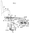
- the aforementioned supporting device 115 comprises according to Fig. 2 a supporting frame 116 extending roughly horizontally above the rear wheel or above the luggage carrier 102 indicated by the dot-dashed line in Fig. 2, two forward-oriented fastener brackets 117,118 connectable to the saddle tube 105 of the bicycle 101, and two supporting struts119, 120 which are fastenable by their free or lower ends 121, 122 to the two struts 107 of the rear wheel fork 106 of the bicycle 101.
- the fastener bracket 117, the supporting strut 119 and the lower end 121 assigned to this supporting strut 119 each extend in the forward direction on the right-hand side of the bicycle center plane defined by the bicycle frame and the two wheels, whilst the fastener bracket 118, the supporting strut 120 and the lower end 122 assigned to the latter are each located on the left-hand side of the bicycle.
- the two fastener brackets 117, 118 for securing to the saddle tube 105 bypass the rear wheel fork 106 so that connecting the fastener brackets to the saddle tube 105 can be made without being obstructed by connecting parts on the rear wheel fork 106 between the bicycle saddle 104 and the rear wheel 109.
- the kiddy seat is connectable, among other things by bypassing the rear wheel fork, to the saddle tube 105 of the bicycle frame which is stiffer in any case, i.e. without obstruction both by conventional connecting parts of the bicycle and without obstruction to the cyclist.
- the fastener brackets 117, 118 are oriented to closely bypass the two struts 107 of the rear wheel fork 106 below the bicycle saddle 104. More specifically, when fitted the fastener brackets 117, 118 are each curved downwards and towards the saddle tube 105, thus preventing any obstruction by the fastener brackets for both the cyclist and for such conventional connecting parts of the bicycle as the brakes, bicycle lock, luggage carrier and the like.
- the two fastener brackets 117, 118 are each mounted longitudinally shiftable on the supporting frame 116. This longitudinal shift ability is indicated in Fig. 2 by the double arrow 123.
- Fig. 2 two different positions of the fastener brackets 117, 118 relative to the supporting frame 116 are illustrated in Fig. 2, i.e.
- the two fastener brackets 117, 118 are each held rotatable about their longitudinal axes on the supporting frame 116. This ability to rotate is indicated in Fig. 2 by the double arrow 125.
- the fastener brackets 117, 118 are each turned within their bearings on the supporting frame 116 so that their saddle tube connecting ends each face outwardly. Then the supporting frame 116 can be swivelled about the connecting point 124 on the struts 107 of the rear wheel fork 106 into the installation or removal position without being obstructed by the bicycle saddle 104 and the like.
- the fastener brackets 117, 118 are preferably made of tubular plastic or light-alloy. In the Figs. 3 and 4 each of the fastener brackets 117, 118 are illustrated in the front view, i.e. in the direction III and IV resp. in Fig. 2.
- the free or saddle tube connecting ends of the fastener brackets 117, 118 can each be connected to the other, namely plugged together in forming a pin or tube-like connecting section 126 extending horizontally.
- the fastener brackets 117, 118 are each bent at their front ends and capable of being plugged together to form the horizontal connecting section 126 (projection 127 in the form of truncated cone at the free forward end of the partial section of the connecting section 126 assigned to the fastener bracket 117; complementary recess 128 on the free forward end of the partial section of the connecting section 126 assigned to the fastener bracket 118.
- the connecting section 126 features hook-like latching projections 129 and 130 resp. which are latchable in a complementary opening 131 of a support 132 secured to the saddle tube 105.
- the connecting section extending transversely to the plane of the bicycle or extending horizontally is in contact with a semi-bucket shaped supporting surface 133 of the support 132.
- the two latching projections 129, 130 are in the latching position within the latching opening 131.
- the semi-bucket shaped supporting surface 133 of the support 132 is located at the end of the saddle tube 105 opposite the supporting frame 116 or at the front end.
- the latching opening 131 is formed more or less centrally in the region of the supporting surface 133.
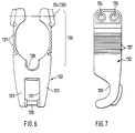
- Figs. 6 and 7 the support 132 is shown both in the side view and in the plan view. Accordingly this involves a kind of clip made of plastic and the like which can be clamped to the saddle tube 105 by bolting.
- the corresponding bolt holes are identified by the references numerals 134, 135 in Figs. 6 and 7.
- the two arms of the clip section 136 of the support 132 gripping the saddle tube 105 are provided with less material, i.e. more specifically slightly thinner walled and with ribs 137.
- the opening for the saddle tube 105 is followed by a recess 138 for passing through electric cables and the like so that the routing of such cables is not obstructed by the fastening of the support 132 on the saddle tube 105.
- the front end of the latching opening 131 is limited by a cross-pin 139 about which a locking hook (not shown) is free to swivel and by means of which the latching connection between the fastener brackets 117, 118 and the support 132 can be locked.
- the hook-like latching projections 129, 130 are formed namely as integrally molded bending straps 140, 141 arranged on the connecting section 126, these bending straps 140, 141 extending parallel to the center plane of the bicycle.
- the free ends of the bending straps 140, 141 project as shown in Fig. 2 from the side opposite the insertion side, namely from the lower side of the latching opening 131 formed in the support 132 so that by bending the protruding ends towards each other the latching projections 129, 130 can be brought into their latching position.
- the fastener brackets 117, 118 are mounted longitudinally shiftable on the supporting frame 116 to adapt to the differing configurations of the wheels and frame of the bicycle.
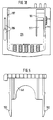
- the longitudianally shiftable mounted sections 144 of the two fastener brackets 117, 118 are each configured with transverse ribs (Fig. 2), locating the position of each fastener bracket relative to the supporting frame being achieved by means of holding clips 146 (see Fig. 5) effective between two neighboring ribs 145.
- the holding clip 146 can be anchored in the supporting frame 116, i.e. within an insertion opening 149 extending crosswise to the receiving opening 147 and 148 in each case (see Fig. 8) for the fastener brackets 117, 118 resp.
- FIG. 2 in the supporting frame 116.
- the holding clip 146 its arms are each provided with latching projections 150 corresponding with complementary latching openings in the supporting frame 116.
- the upper side of the clips 146 is configured so that they each come to rest flush with the upper side of the supporting frame 116 in the latching position.
- the supporting frame 116 including the supporting struts 119, 120 is made in one piece of plastic, whereby each of the supporting struts 119, 120 is formed as square hollow sections.
- hanger slots are formed at a predetermined space from each other which in the installed condition of the supporting frame vertically extend in the longitudinal direction of support. As regards the function of these hanger slots reference is made to the details provided further on. These serve to attach foot rests 150, 151.
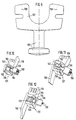
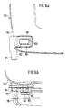
- each lock 152 comprises a rotary latch 153 which in the open position (Fig. 12) opens up a receiving slot 124 ( see Figs 2, 10 thru 12) formed on the lower free end 121 and 122 resp.
- the rotary latch 153 which is configured as a circular bucket section is connected to a manipulator 156.
- This manipulator 156 also functions as an outer screen for the lower free end 121 and 122 resp. of each supporting strut 119, 120.
- the manipulator 156 In the closed position of the rotary latch 153 the manipulator 156 is located as shown in Fig. 10 in a covering position. In this position the manipulator 156 and thus also the rotary latch 155 is preferably latched.
- the corresponding latching arrangement is not indicated in finer detail in Figs 10 to 12 since the arrangement concerned is known as such.
- the mushroom-headed pin 155 is further provided with a U-shaped connecting part 157 by means of which fastening of the associated strut 107 of the rear wheel fork 106 is made.
- the counterpart thereof is not shown in finer detail in the Figures which, in any case, is bolted to the free ends of the two arms of the U-shaped connecting part 157.
- the corresponding threaded pins 158 are securely embedded in the connecting part 157. In Fig. 9 these threaded pins 158 are merely indicated by their center lines.
- the connecting part 157 may be produced integral with the mushroom-headed pin 155 in plastic or metal. When made of plastic the aforementioned threaded pins 158 are molded in place resistant to turning and tension. In conclusion it is to be noted that that the receiving slots 154 are each provided with an undercut 159 to receive the mushroom-head shaped end of the pin 155.
- the supporting frame 116 features at its two rear corners a total of two slot-like openings 160 which are accessible from above, each provided with an undercut 161 to receive a toggle-like locking member 162 arranged on the kiddy seat 103.
- the locking toggles 162 are rotatably mounted on the base of the kiddy seat 103 or alternatively on the base of a case-like container and the like so that they are located at a distance below the underside of the base of the kiddy seat 103 and insertable in the slot-like openings 160 of the supporting frame 116.
- the rotary axes 163 with which the locking toggles 162 are jointed are each connected to a locking lever 164 accessible from the exterior with which the double-hammer shaped locking toggles can each be swivelled thru 90°, i.e. - after being introduced into the slot-shaped receiving openings 160 - into a locking position as shown in Figs. 15a, 15b in which they are rotatable and in which the free ends of the locking toggles 162 engage from underneath the undercuts 161 assigned to the slot-like openings 160.
- the supporting frame 116 features at its front end two insertion openings 165, 166 spaced away from each other to receive suitable projections 167, 168 oriented to the rear on the kiddy seat 103.
- the projections 167, 168 are introduced into the forward insertion openings 165.
- 166 of the supporting frame 116 The kiddy seat 103 is then tilted about the insertion openings 165, 166 to the rear on the supporting frame 116 and simultaneously the locking toggles 162 introduced into the corresponding receiving openings 160 on the upper side of the supporting frame 116 as illustrated in Figs. 14a, 14b.
- the locking levers 164 are then swivelled from the position shown in Figs. 14a, 14b into a locking position as shown in Figs. 15a, 15b.
- the locking levers 164 preferably latch in the position as shown in Figs. 15a, 15b so that the kiddy seat 103 is reliably held on the supporting frame 116.
- the underside of the kiddy seat 103 additionally features a substantially circumferential edge 169 formed as a curb within which the upper side of the supporting frame 116 is held.
- a circumferential edge is formed on the upper side of the supporting frame 116 within which the underside of the kiddy seat is reliably held in all horizontal directions in the aforementioned way.
- the two aforementioned projections 167, 168 are formed on a front projection 170 of the base of the kiddy seat 103. This projection is integrally connected to the kiddy seat 103.
- a connection 171 for a seat belt (not shown) is provided in the middle of the front edge area of the base of the kiddy seat 103.
- a particularly advantageous embodiment of a foot rest 150 (including the opposite foot rest 151) will now be detailled which can also be employed independently of the aforementioned structure of a supporting device for a kiddy seat. To this extent patenting thereof is also herewith claimed independently.
- both of the supporting struts 119, 120 feature a plurality of hanger slots 172 located one above the other and each extending in the longitudinal direction of the supporting struts and vertically respectively for height-adjustable hanging attachment of the foot rests 150 and 151 resp., whereby the corresponding anchoring members are formed on the foot rests 150 and 151 resp. by an upper hook-like holding projection 173 oriented upwards, a lower hook-like holding projection 174 oriented downwards and by a locking projection 175 which can be introduced in the hanging position of the foot rest into a separate opening, in this case also hanger slot 172.
- the locking projection 175 is formed between the upper and lower holding projection, relative to which it is held pliantly, so that for locating the foot rest 150 and 151 resp. at each supporting strut 119 and 120 resp. first the upper holding projection 173 can be introduced into the corresponding hanger slot 172 and shifted upwards whilst hooking therein together with the foot rest, whereby the lower holding projection 174 can also be introduced into the corresponding lower hanger slot 172 so that then the foot rest 150 and 151 resp. - with simultaneous hook attachment also of the lower holding projection and forcing-away of the locking projection 175 by the facing limitation of the supporting strut 119 and 120 resp. - can be shifted sufficiently downwards until the foot rest 150 and 151 resp. engages the lower edge of the assigned hanger slot 172 by its lower holding projection 174 and the locking projection 175 snaps into place in a correspondingly assigned locking opening or in a hanger slot 172 located inbetween.
- the foot rest 150 and 151 resp. is each produced as a bucket quadrant of plastic.
- the aforementioned holding projections including the locking projection are integral components of the foot rest.
- the locking projection 175 is formed at the upper end of a strap 177 stamped in the rear wall or - in the fitted position - in the wall 176 adjoining the supporting strut 119 and 120 resp., particularly molded therein and oriented in the direction of the foot rest.
- the distance between the hanger slot ends facing away from each other of the hanger slot assigned on the one hand to the upper holding projection and that assigned on the other to the lower holding projection is - again on the one hand - smaller than the distance between the free ends of the two holding projections and - again on the other - is greater, however, than the distance between the free end 178 of the lower holding projection 174 and the upper side 179 of the raised face 180 of the upper holding projection 173.
- Dimensioning the spacing in this way permits hanging and anchor attachment of the foot rest 150 and 151 resp. on the supporting struts 119, 120 as described above. Removal of the foot rest 150 and 151 resp. is done in the reverse sequence.
- an opening 181 is provided in the foot rest and Its rear wall 176 resp. through which the locking projection and the upper end of the strap 177 carrying the locking projection 175 resp. is accessible e.g. by one finger and the locking projection 175 is withdrawable from the assigned locking opening, which in this case is the assigned hanger slot 172 by overcoming the pliant preloading of the strap 177 carrying the locking projection 175.
- the foot rest 150 and 151 resp. is formed as a kind of bucket quadrant of plastic, a foot strap 183 being intregally molded on a sidewall 182 - the sidewall facing the rear wheel in each case when the foot rest is installed.
- the foot strap 183 is provided with transverse ribs 184 to reduce its flexural rigidity or to provide it with a flexural rigidity corresponding to that of a leather strap and the like. With its free end 185 leading, the foot strap 183 can be introduced into a slot-like opening 186 in the opposite sidewall 187 - the exterior sidewall in each case when the foot rest is installed - in which it can be hooked by means of the transverse ribs 184.
- each foot rest 150, 151 is formed ribbed in each case as is evident from Figs. 16 and 18.
Landscapes
- Health & Medical Sciences (AREA)
- Child & Adolescent Psychology (AREA)
- General Health & Medical Sciences (AREA)
- Engineering & Computer Science (AREA)
- Mechanical Engineering (AREA)
- Motorcycle And Bicycle Frame (AREA)
- Automatic Cycles, And Cycles In General (AREA)
- Axle Suspensions And Sidecars For Cycles (AREA)
- Carriages For Children, Sleds, And Other Hand-Operated Vehicles (AREA)
Claims (23)
- Vorrichtung zum lösbaren Befestigen eines Kindersitzes (103), eines kastenartigen Behälters und dergleichen über dem Hinterrad (109) eines Fahrrads (101), wobei die Vorrichtung folgendes aufweist einen Tragrahmen (116), der sich grob horizontal über dem Hinterrad (109) erstreckt, zwei Befestigungsarme (117, 118), die jeweils nach vorn orientiert und an dem Tragrahmen (116) in Längsrichtung verschiebbar (Doppelpfeil 123) angebracht sind und die zum Befestigen an dem Sattelrohr (105) des Fahrrads (101) jeweils imstande sind, um die Hinterradgabel (106) herum zu verlaufen, und ferner zwei Stützstreben (119, 120), die jeweils an dem Tragrahmen (116) angebracht sind und deren freie Enden (121, 122) jeweils an den beiden Streben (107) der Hinterradgabel (106) des Fahrrads (101) befestigbar sind, dadurch gekennzeichnet, daß in der eingebauten Position jeder der Befestigungsarme (117, 118) nach unten zu dem Sattelrohr (105) gekrümmt ist und sich somit an der Außenseite der beiden Streben (107) der Hinterradgabel (106) und daran vorbei erstreckt, bevor er an dem Sattelrohr (105) an einer Stelle unterhalb des Verbindungspunkts zwischen den Streben (107) der Hinterradgabel (106) und dem Sattelrohr (105) befestigt ist, wobei die Befestigungsarme (117, 118) in ihrer Halterung an dem Tragrahmen (116) jeweils um ihre Längsachsen (Doppelpfeil 125) drehbar gehalten sind.
- Vorrichtung nach Anspruch 1, wobei die freien oder vorderen Enden der Befestigungsarme (117, 118), während sie einen Verbindungsabschnitt (126) bilden, der sich grob horizontal oder quer zu der durch den Fahrradrahmen definierten Mittelebene des Fahrrads erstreckt, miteinander verbindbar sind.
- Vorrichtung nach Anspruch 2, wobei der Verbindungsabschnitt (126) hakenartige Verriegelungsvorsprünge (129, 130) aufweist, die in einer komplementären Öffnung (131) einer Halterung (132), die an dem Sattelrohr (105) befestigt ist, verrastbar sind.
- Vorrichtung nach Anspruch 2 oder 3, wobei der Verbindungsabschnitt (126) als ein rohrförmiger Abschnitt ausgebildet ist, der mit einer halb-becherförmigen Stützfläche (133) der Halterung (132) in der Einrastposition der zugehörigen Verriegelungsvorsprünge (129, 130) in Kontakt ist.
- Vorrichtung nach Anspruch 4, wobei die halb-becherförmige Stützfläche (133) der Halterung (132) an der dem Tragrahmen (116) entgegengesetzten Seite oder Vorderseite des Sattelrohrs (105) liegt und die Stützfläche (133) eine zentrale Öffnung (131) zum Einrasten der hakenartigen Verriegelungsvorsprünge (129, 130) hat.
- Vorrichtung nach einem der Ansprüche 3 bis 5, wobei die hakenartigen Verriegelungsvorsprünge (129, 130) insbesondere als integral geformte Biegebügel (140, 141) ausgebildet sind, die an dem Verbindungsabschnitt (126) angeordnet sind, wobei die freien Enden der Biegebügel (140, 141) von der zu der Einführungsseite entgegengesetzten Seite, insbesondere von der unteren Seite der in der Halterung (132) ausgebildeten Verriegelungsöffnung (131), vorspringen.
- Vorrichtung nach einem der Ansprüche 1 bis 6, wobei der Abschnitt der Befestigungsarme (117, 118), der längsverschiebbar an dem Tragrahmen (116) angeordnet ist, in jedem Fall mit Querrippen ausgebildet ist, so daß die relative Position zwischen den Befestigungsarmen und dem Tragrahmen mit Hilfe von Halteclips (146) bestimmt wird, die zwischen zwei benachbarten Querrippen (145) wirksam sind.
- Vorrichtung nach Anspruch 7, wobei der Halteclip (146) in dem Tragrahmen (116) verankert, speziell arretiert werden kann, und zwar bevorzugt in einer Einführöffnung (149), die quer zu der Aufnahmeöffnung (147, 148) für die Befestigungsarme (117, 118) in dem Tragrahmen (116) verläuft.
- Vorrichtung nach einem der Ansprüche 1 bis 8, wobei das Befestigen der Stützstreben (119, 120) an den beiden Streben (107) der Hinterradgabel (106) in jedem Fall über ein nichtformschlüssiges Schloß (152) erfolgt, das in der geschlossenen Position (Fig. 10) ein Schwenken des Tragrahmens (116) in der vertikalen (Fahrrad-)Ebene zuläßt.
- Vorrichtung nach Anspruch 9, wobei jedes Schloß (152) eine Klinke, insbesondere eine drehbare Klinke (153) aufweist, die in der offenen Position (Fig. 12) einen Aufnahmeschlitz (154), der an dem freien Ende (121, 122) der Stützstreben (119, 120) ausgebildet ist, für einen Stift, insbesondere einen Flachrundkopfstift (155) öffnet, der an der Seite an der Strebe (107) der Hinterradgabel (106) nach außen vorspringt, und die in der geschlossenen Position diesen Aufnahmeschlitz (154) durch Bilden einer Schwenklageröffnung für den Stift (155) verschließt oder abschließt.
- Vorrichtung nach Anspruch 10, wobei die Klinke, speziell drehbare Klinke (155), in der geschlossenen Position arretierbar ist.
- Vorrichtung nach einem der Ansprüche 1 bis 11, wobei der Tragrahmen (116) wenigstens eine, insbesondere zwei schlitzähnliche Öffnungen (160) aufweist, die von oben zugänglich und jeweils mit einer Unterschneidung (161) versehen sind, um ein an dem Kindersitz (103) angeordnetes kniehebelartiges Arretierelement (162) aufzunehmen.
- Vorrichtung nach Anspruch 12, wobei der Tragrahmen (116) an seinem Vorderende wenigstens eine, insbesondere zwei Einführöffnungen (165, 166) aufweist, die voneinander beabstandet sind, um geeignete Vorsprünge (167, 168) an dem Kindersitz (103) und dergleichen aufzunehmen, und wobei die zwei schlitzähnlichen Öffnungen (160) zur Aufnahme der komplementären Arretierelemente (162) jeweils in dem Bereich der beiden hinteren Ecken des Tragrahmens (116) ausgebildet sind, so daß nach dem Einführen der Vorsprünge (167, 168) in die vorderen Aufnahmeöffnungen (165, 166) des Tragrahmens (116) ein Kindersitz und dergleichen um sie herum nach rückwärts an dem Tragrahmen (116) gekippt werden kann, so daß er mittels der Arretierelemente (162) zuverlässig an dem Tragrahmen (116) befestigt ist.
- Vorrichtung nach Anspruch 12 oder 13, wobei an der Unterseite des Kindersitzes (103) und dergleichen ein im wesentlichen um den Umfang verlaufender Rand (169) als eine Einfassung geformt ist, innerhalb welcher die obere Seite des Tragrahmens (116) positionierbar ist, oder umgekehrt.
- Vorrichtung nach einem oder mehreren der Ansprüche 1 bis 14, wobei die Stützstreben (119, 120) jeweils eine Vielzahl von Einhängeschlitzen (172) haben, die einzeln übereinander positioniert sind und jeweils in der Längsrichtung der Stützstreben bzw. vertikal verlaufen, um die Fußstützen (150, 151) höhenverstellbar hängend anzubringen, wobei die entsprechenden Verankerungselemente an den Fußstützen (150, 151) gebildet sind durch einen oberen hakenartigen Haltevorsprung (173), der nach oben orientiert ist, einen unteren hakenartigen Haltevorsprung (174), der nach unten orientiert ist, und durch einen Arretiervorsprung (175), der in der Hängeposition der Fußstütze (150, 151) in eine separate Öffnung (172) an der Stützstrebe (119, 120) oder in einen dazwischen liegenden Einhängeschlitz (172) einführbar ist.
- Vorrichtung nach Anspruch 15, wobei der Arretiervorsprung (175) zwischen dem oberen und dem unteren Haltevorsprung ausgebildet ist, relativ zu welchem er biegbar gehalten ist, so daß zum Festlegen der Fußstütze (150, 151) an einer Stützstrebe (119, 120) zuerst der obere Haltevorsprung (173) in den Einhängeschlitz (172) eingeführt werden kann und unter Hakenbefestigung an demselben mit der Fußstütze ausreichend weit nach oben verlagerbar ist, so daß der untere Haltevorsprung (174) in den zugehörigen unteren Einhängeschlitz (172) der Fußstütze (150, 151) eingeführt werden kann und dann nach unten ausreichend weit verlagerbar ist - ebenfalls unter Hakenbefestigung des unteren Haltevorsprungs (174) und gleichzeitigem Wegdrücken des Arretiervorsprungs (175) durch den zugewandten Begrenzungsrand der Stützstrebe (119, 120) -, bis die Fußstütze (150, 151) mit dem unteren Rand des zugeordneten Einhängeschlitzes (172) über ihren unteren Haltevorsprung (174) in Berührung gelangt und der Arretiervorsprung (175) in einer entsprechend angeordneten Arretieröffnung oder in dem dazwischen befindlichen Einhängeschlitz (172) in seine Lage schnappt.
- Vorrichtung nach Anspruch 16, wobei der Abstand zwischen den voneinander weg weisenden Schlitzenden jedes oberen Einhängeschlitzes, der dem oberen Haltevorsprung zugeordnet ist, und jedes unteren Einhängeschlitzes, der dem unteren Haltevorsprung zugeordnet ist, einerseits kleiner als der Abstand zwischen den freien Enden der beiden Haltevorsprünge (173, 174) jeder Fußstütze (150, 151) gemacht ist, jedoch andererseits größer als der Abstand zwischen dem freien Ende (178) des unteren Haltevorsprungs (174) und der oberen Seite (179) der erhöhten Fläche (180) des oberen Haltevorsprungs (173) an der Fußstütze (150, 151) bzw. seiner Rückwand (176) gemacht ist.
- Vorrichtung nach Anspruch 15 oder 16, wobei eine Öffnung (181) in der Fußstütze (150, 151) bzw. ihrer Rückwand (176) vorgesehen ist, durch die der Arretiervorsprung (175) zugänglich ist, und zwar insbesondere mit einem Finger, und wobei der Arretiervorsprung (175) aus der Arretieröffnung in der Stützstrebe (119, 120) und aus dem entsprechend zugeordneten Einhängeschlitz (172) herausziehbar ist, indem seine elastische Vorspannung überwunden wird.
- Vorrichtung nach einem der Ansprüche 15 bis 18, wobei die Fußstütze (150, 151) als eine Art von Becherquadrant geformt ist, wobei ein Fußgurt (183) an einer Seitenwand (182) integral angeformt ist.
- Vorrichtung nach Anspruch 19, wobei der Fußgurt (183) Querrippen (184) - bevorzugt an der Außenseite - aufweist und mit seinem freien Ende (185) zuerst in eine schlitzartige Öffnung (186) in der gegenüberstehenden Seitenwand (187) einführbar ist, in der er mittels der Querrippen (184) verrastet werden kann.
- Vorrichtung nach einem der Ansprüche 1 bis 20, wobei der Tragrahmen (116) einschließlich der Stützstreben (119, 120) integral aus Kunststoff hergestellt ist.
- Vorrichtung nach einem der Ansprüche 1 bis 21, wobei die Befestigungsarme (117, 118) aus rohrförmigem Kunststoff oder Leichtmetall hergestellt sind.
- Vorrichtung nach einem der Ansprüche 1 bis 22, wobei die Sattelrohrhalterung (132), die Befestigungsarme (117, 118), die Fußstützen (150, 151) und der Kindersitz (103), Behälter und dergleichen jeweils aus Kunststoff hergestellt sind.
Applications Claiming Priority (2)
| Application Number | Priority Date | Filing Date | Title |
|---|---|---|---|
| DE4226713 | 1992-08-12 | ||
| DE4226713A DE4226713A1 (de) | 1992-08-12 | 1992-08-12 | Vorrichtung zur lösbaren Anbringung eines Kindersitzes oder dergleichen oberhalb des hinteren Rades eines Fahrrads |
Publications (2)
| Publication Number | Publication Date |
|---|---|
| EP0583013A1 EP0583013A1 (de) | 1994-02-16 |
| EP0583013B1 true EP0583013B1 (de) | 1997-07-09 |
Family
ID=6465412
Family Applications (1)
| Application Number | Title | Priority Date | Filing Date |
|---|---|---|---|
| EP93112969A Expired - Lifetime EP0583013B1 (de) | 1992-08-12 | 1993-08-12 | Gerät zur demontierbaren Befestigung eines Kindersitzes und dergleichen über dem Hinterrad eines Fahrrads |
Country Status (3)
| Country | Link |
|---|---|
| EP (1) | EP0583013B1 (de) |
| AT (1) | ATE155094T1 (de) |
| DE (2) | DE4226713A1 (de) |
Families Citing this family (3)
| Publication number | Priority date | Publication date | Assignee | Title |
|---|---|---|---|---|
| EP2236397A1 (de) * | 2009-03-30 | 2010-10-06 | Dremefa Beheer B.V. | Montageanordnung für einen Kinderfahrradsitz |
| EP2275332A1 (de) | 2009-07-16 | 2011-01-19 | Hamax As | Beuteladapter |
| CN104925170A (zh) * | 2015-06-04 | 2015-09-23 | 张朋炬 | 一种后备箱式儿童安全座椅 |
Family Cites Families (7)
| Publication number | Priority date | Publication date | Assignee | Title |
|---|---|---|---|---|
| US3802598A (en) * | 1972-04-14 | 1974-04-09 | Sears Roebuck & Co | Rear carrier for bicycle |
| US4030648A (en) * | 1976-09-20 | 1977-06-21 | The Firestone Tire & Rubber Company | Carrier support apparatus |
| DE8511417U1 (de) * | 1985-04-17 | 1985-07-18 | Kohler, Hans, 7750 Konstanz | Kindersitz |
| DE8603549U1 (de) * | 1986-02-11 | 1986-07-17 | Heinz Kettler Metallwarenfabrik GmbH & Co, 59469 Ense | Kindersitz für ein Fahrrad |
| NL8801549A (nl) * | 1988-06-17 | 1990-01-16 | Joannes Drexler | Kinderzit. |
| DE9012792U1 (de) * | 1990-09-07 | 1990-11-08 | Braunewell, Amadeus, Dr. Med. | Fahrradkindersitz |
| DE9204494U1 (de) * | 1992-04-02 | 1992-05-27 | Framework Fahrradbau GmbH, 4750 Unna | Halterung zur lösbaren Befestigung eines Bauteiles an einem Fahrrad |
-
1992
- 1992-08-12 DE DE4226713A patent/DE4226713A1/de not_active Withdrawn
-
1993
- 1993-08-12 AT AT93112969T patent/ATE155094T1/de not_active IP Right Cessation
- 1993-08-12 EP EP93112969A patent/EP0583013B1/de not_active Expired - Lifetime
- 1993-08-12 DE DE69311983T patent/DE69311983T2/de not_active Expired - Fee Related
Also Published As
| Publication number | Publication date |
|---|---|
| DE4226713A1 (de) | 1994-02-17 |
| ATE155094T1 (de) | 1997-07-15 |
| DE69311983D1 (de) | 1997-08-14 |
| DE69311983T2 (de) | 1998-02-19 |
| EP0583013A1 (de) | 1994-02-16 |
Similar Documents
| Publication | Publication Date | Title |
|---|---|---|
| US4730758A (en) | Detachable bicycle basket | |
| CN109661328B (zh) | 交通工具挂接安装的自行车支架 | |
| US6659547B2 (en) | Adjustable back rest and cargo carrier for a motorcycle | |
| US5195670A (en) | Bicycle rack with adjustable pin locking | |
| US4676413A (en) | Vehicle frame mounted bicycle carrier | |
| US3795354A (en) | Luggage attachment for tandem-wheeled vehicle | |
| US6206259B1 (en) | Hitch mountable bicycle carrier | |
| US9358933B2 (en) | Trunk mounted bike carrier | |
| CA2471149A1 (en) | Carrier for attachment to a bicycle | |
| CA2789675C (en) | Wheelchair back mounting assembly | |
| JPS6243903B2 (de) | ||
| DK2168853T3 (en) | System for hanging bags or containers of luggage racks | |
| WO2002018177A1 (en) | Bicycle holder for vehicles | |
| EP0583013A1 (de) | Gerät zur demontierbaren Befestigung eines Kindersitzes und dergleichen über dem Hinterrad eines Fahrrads | |
| CN1198136A (zh) | 容器组 | |
| EP0236635B1 (de) | Sitzgelegenheit an einer Leiter | |
| JP3137975B2 (ja) | 荷物キャリヤ装置 | |
| US5800014A (en) | Adjustable child seat for bicycles | |
| EP0337552B1 (de) | Gepäckträger mit entfernbarem Bügelschloss | |
| US5655696A (en) | Adjustable bicycle rack | |
| EP0687234A1 (de) | Verbesserungen an sattelträgern und schlössern | |
| EP0417419B1 (de) | Befestigungseinrichtung für Fahrradzubehör | |
| JP4152336B2 (ja) | 補助具取付装置 | |
| AU2023200968B1 (en) | A Bicycle Rack | |
| EP0603306A1 (de) | Vorrichtung zur befestigung eines lastträgers |
Legal Events
| Date | Code | Title | Description |
|---|---|---|---|
| PUAI | Public reference made under article 153(3) epc to a published international application that has entered the european phase |
Free format text: ORIGINAL CODE: 0009012 |
|
| AK | Designated contracting states |
Kind code of ref document: A1 Designated state(s): AT DE FR GB IT NL SE |
|
| 17P | Request for examination filed |
Effective date: 19940419 |
|
| 17Q | First examination report despatched |
Effective date: 19950112 |
|
| GRAG | Despatch of communication of intention to grant |
Free format text: ORIGINAL CODE: EPIDOS AGRA |
|
| GRAH | Despatch of communication of intention to grant a patent |
Free format text: ORIGINAL CODE: EPIDOS IGRA |
|
| GRAH | Despatch of communication of intention to grant a patent |
Free format text: ORIGINAL CODE: EPIDOS IGRA |
|
| GRAA | (expected) grant |
Free format text: ORIGINAL CODE: 0009210 |
|
| AK | Designated contracting states |
Kind code of ref document: B1 Designated state(s): AT DE FR GB IT NL SE |
|
| PG25 | Lapsed in a contracting state [announced via postgrant information from national office to epo] |
Ref country code: NL Free format text: LAPSE BECAUSE OF FAILURE TO SUBMIT A TRANSLATION OF THE DESCRIPTION OR TO PAY THE FEE WITHIN THE PRESCRIBED TIME-LIMIT Effective date: 19970709 |
|
| REF | Corresponds to: |
Ref document number: 155094 Country of ref document: AT Date of ref document: 19970715 Kind code of ref document: T |
|
| REF | Corresponds to: |
Ref document number: 69311983 Country of ref document: DE Date of ref document: 19970814 |
|
| PGFP | Annual fee paid to national office [announced via postgrant information from national office to epo] |
Ref country code: FR Payment date: 19970818 Year of fee payment: 5 |
|
| ET | Fr: translation filed | ||
| ITF | It: translation for a ep patent filed | ||
| PG25 | Lapsed in a contracting state [announced via postgrant information from national office to epo] |
Ref country code: SE Effective date: 19971009 |
|
| NLV1 | Nl: lapsed or annulled due to failure to fulfill the requirements of art. 29p and 29m of the patents act | ||
| PLBE | No opposition filed within time limit |
Free format text: ORIGINAL CODE: 0009261 |
|
| 26N | No opposition filed | ||
| PGFP | Annual fee paid to national office [announced via postgrant information from national office to epo] |
Ref country code: GB Payment date: 19980729 Year of fee payment: 6 |
|
| PGFP | Annual fee paid to national office [announced via postgrant information from national office to epo] |
Ref country code: AT Payment date: 19980821 Year of fee payment: 6 |
|
| PGFP | Annual fee paid to national office [announced via postgrant information from national office to epo] |
Ref country code: DE Payment date: 19981029 Year of fee payment: 6 |
|
| PG25 | Lapsed in a contracting state [announced via postgrant information from national office to epo] |
Ref country code: FR Free format text: LAPSE BECAUSE OF NON-PAYMENT OF DUE FEES Effective date: 19990430 |
|
| REG | Reference to a national code |
Ref country code: FR Ref legal event code: ST |
|
| PG25 | Lapsed in a contracting state [announced via postgrant information from national office to epo] |
Ref country code: GB Free format text: LAPSE BECAUSE OF NON-PAYMENT OF DUE FEES Effective date: 19990812 Ref country code: AT Free format text: LAPSE BECAUSE OF NON-PAYMENT OF DUE FEES Effective date: 19990812 |
|
| GBPC | Gb: european patent ceased through non-payment of renewal fee |
Effective date: 19990812 |
|
| PG25 | Lapsed in a contracting state [announced via postgrant information from national office to epo] |
Ref country code: DE Free format text: LAPSE BECAUSE OF NON-PAYMENT OF DUE FEES Effective date: 20000601 |
|
| PG25 | Lapsed in a contracting state [announced via postgrant information from national office to epo] |
Ref country code: IT Free format text: LAPSE BECAUSE OF NON-PAYMENT OF DUE FEES Effective date: 20050812 |