EP0579848A1 - Prüfanlage für Gegenstände - Google Patents
Prüfanlage für Gegenstände Download PDFInfo
- Publication number
- EP0579848A1 EP0579848A1 EP92112381A EP92112381A EP0579848A1 EP 0579848 A1 EP0579848 A1 EP 0579848A1 EP 92112381 A EP92112381 A EP 92112381A EP 92112381 A EP92112381 A EP 92112381A EP 0579848 A1 EP0579848 A1 EP 0579848A1
- Authority
- EP
- European Patent Office
- Prior art keywords
- operating unit
- monitor
- imaging system
- objects
- objects according
- Prior art date
- Legal status (The legal status is an assumption and is not a legal conclusion. Google has not performed a legal analysis and makes no representation as to the accuracy of the status listed.)
- Granted
Links
- 238000012360 testing method Methods 0.000 title claims abstract description 14
- 238000003384 imaging method Methods 0.000 claims description 34
- 230000008878 coupling Effects 0.000 claims description 2
- 238000010168 coupling process Methods 0.000 claims description 2
- 238000005859 coupling reaction Methods 0.000 claims description 2
- 238000007689 inspection Methods 0.000 claims 7
- 230000005855 radiation Effects 0.000 description 14
- 238000010521 absorption reaction Methods 0.000 description 1
- 238000000034 method Methods 0.000 description 1
- 230000001360 synchronised effect Effects 0.000 description 1
Images
Classifications
-
- A—HUMAN NECESSITIES
- A61—MEDICAL OR VETERINARY SCIENCE; HYGIENE
- A61B—DIAGNOSIS; SURGERY; IDENTIFICATION
- A61B6/00—Apparatus or devices for radiation diagnosis; Apparatus or devices for radiation diagnosis combined with radiation therapy equipment
- A61B6/46—Arrangements for interfacing with the operator or the patient
- A61B6/461—Displaying means of special interest
- A61B6/464—Displaying means of special interest involving a plurality of displays
-
- G—PHYSICS
- G01—MEASURING; TESTING
- G01N—INVESTIGATING OR ANALYSING MATERIALS BY DETERMINING THEIR CHEMICAL OR PHYSICAL PROPERTIES
- G01N23/00—Investigating or analysing materials by the use of wave or particle radiation, e.g. X-rays or neutrons, not covered by groups G01N3/00 – G01N17/00, G01N21/00 or G01N22/00
- G01N23/02—Investigating or analysing materials by the use of wave or particle radiation, e.g. X-rays or neutrons, not covered by groups G01N3/00 – G01N17/00, G01N21/00 or G01N22/00 by transmitting the radiation through the material
- G01N23/04—Investigating or analysing materials by the use of wave or particle radiation, e.g. X-rays or neutrons, not covered by groups G01N3/00 – G01N17/00, G01N21/00 or G01N22/00 by transmitting the radiation through the material and forming images of the material
- G01N23/043—Investigating or analysing materials by the use of wave or particle radiation, e.g. X-rays or neutrons, not covered by groups G01N3/00 – G01N17/00, G01N21/00 or G01N22/00 by transmitting the radiation through the material and forming images of the material using fluoroscopic examination, with visual observation or video transmission of fluoroscopic images
-
- H—ELECTRICITY
- H05—ELECTRIC TECHNIQUES NOT OTHERWISE PROVIDED FOR
- H05G—X-RAY TECHNIQUE
- H05G1/00—X-ray apparatus involving X-ray tubes; Circuits therefor
- H05G1/08—Electrical details
- H05G1/26—Measuring, controlling or protecting
- H05G1/30—Controlling
-
- H—ELECTRICITY
- H05—ELECTRIC TECHNIQUES NOT OTHERWISE PROVIDED FOR
- H05G—X-RAY TECHNIQUE
- H05G1/00—X-ray apparatus involving X-ray tubes; Circuits therefor
- H05G1/08—Electrical details
- H05G1/70—Circuit arrangements for X-ray tubes with more than one anode; Circuit arrangements for apparatus comprising more than one X ray tube or more than one cathode
Definitions
- a device for radiating objects with fan-shaped radiation which is used, for example, at airports to search the contents of objects for bombs, weapons and contraband.
- this device has a first and a second imaging system, each with a radiation transmitter and a radiation receiver assigned to it. An object can thus be irradiated from different directions.
- the signals of the radiation receivers corresponding to the radiographic image are fed to an image processing device with a computer which creates a visible image from the signals on a monitor of the imaging system.
- Each imaging system has an operating unit so that the exposure parameters of the radiation transmitter required for each exposure can be preset and visible images can be manipulated.
- the invention has for its object to perform a test system for objects so that the operation is simplified and improved compared to the prior art.
- test system for objects with a first and a second imaging system for generating a radiographic image of the object as a visible image on a monitor, a common operating unit being provided for controlling the first and second imaging systems.
- the advantage of the invention is that only one common operating unit is provided for controlling the first and second imaging systems, so that the operation of the imaging systems is simplified.
- the test system for objects can be manufactured more cost-effectively since a second control unit can be dispensed with.
- signals from the control unit are preferably fed to the first and / or second imaging system via a distributor.
- the distributor thus directs signals from the operating unit either to the first and / or to the second imaging system.
- the first or second imaging system fulfills the function of the master or slave.
- the imaging systems can thus communicate with one another.
- data and signals can be transmitted from one imaging system to the other imaging system.
- a first view of the object can be displayed on a monitor of the first imaging system and a second view of the object on a monitor of the second imaging system, wherein the display unit can be manipulated simultaneously.
- the manipulation of the representations therefore no longer has to be carried out separately for each imaging system.
- This embodiment is particularly advantageous if a simultaneous shift of the representations to the Monitors to be effected. It is thus possible to display a top view on the monitor of the first imaging system and a side view of the object on the monitor of the second imaging system, in which case the representations can then be shifted synchronously with one another on the screens of the monitors.
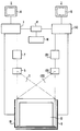
- a test system for objects for example freight, containers, container and / or vehicles, is shown in principle, which has a first and second imaging system 1, 2.
- the imaging systems 1, 2 have the same functional elements, the functional elements of the second imaging system 2 being identified below with reference numbers in parentheses.
- the imaging system 1, (2) has a computing unit 3, (4) for controlling a recording unit, which has a radiation transmitter 5, (6) that can be supplied with energy by a generator 7, (8).
- the radiation transmitter 5, (6) is associated with a radiation receiver 9, (10) which, as the radiation beam 11, (12) of the radiation transmitter 5, (6), after which it has penetrated an object as an examination object, for example a container 13 Radiographic image of the container 13 receives.
- This radiation image is converted by the radiation receiver 9, (10) into electrical signals which are fed to the computing unit 3, (4).
- the arithmetic unit 3, (4) calculates a visible image from these signals, which can be displayed on a monitor 14, (15).
- this is preferably irradiated from different directions, so that different views of the container 13 are shown as representations on the monitors 14, (15).
- the test system for objects shown also has a common operating unit 16, the signals of which can be fed to the computing unit 3, (4).
- the recording parameters of the radiation transmitter 5, (6) which is designed, for example, as an X-ray tube, (kv, mA, t) can be set individually or together via a keyboard for each recording system. It is also possible to manipulate the representations on the monitors 14 (15) at the same time. For example, the contrast and / or the brightness can be changed.
- a simultaneous shift of the representations of the container 13 on the monitors 14, (15) can be effected via the operating unit 16, so that, for example, a side and a top view of the container 13 are shifted synchronously on the screen of the monitors 14, (15) can be.
- a distributor 17 is connected between the operating unit 16 and the computing unit 3, (4), which feeds the signals from the operating unit 16 to the computing unit 3 and / or the computing unit (4). It is thus possible to feed signals from the operating unit 16, for example to the computing unit 3, which processes these signals. The processed signals can then be fed to the computing unit (4) via the distributor 17 to control the second imaging system (2).
- the computing unit 3 is thus the master and the computing unit (4) is therefore the slave.
- the computing unit (4) can also function as the master and the computing unit 3 can function of the slave.
- control unit 16 By means of functional elements of the control unit 16, it can be predetermined whether signals from the control unit 16 are only supplied to the computing unit 3 or also to the computing unit (4), so that arithmetic operations and manipulations of the representations individually or jointly by the computing units 3, (4) for each imaging system 1, 2 are executed.
- a color can be assigned to the gray values assigned to the radiation absorption. It can be specified via the operating unit 16 whether both representations are shown in color or whether one representation is shown in gray values and the other in color on the screen of the monitors 14, (15).
- the representations can be moved individually or synchronously on the screen of the monitors 14, (15). It is also possible to control whether, for example, the contrast and / or the brightness of the representations should be changed individually or together in the same or different way.
- the degree of simultaneous manipulation or coupling between master and slaves can thus be predetermined via the operating unit 16.
- test system for objects according to the invention is provided with two monitors 14, (15), then it is advantageous if synchronized video signals are supplied to them in order to avoid interference and flickering on the screens.
- synchronized video signals are supplied to them in order to avoid interference and flickering on the screens.
- means for generating a window for evaluating the representation on the screen (s) of one monitor or both monitors 14, (15) be provided, the window or windows being controllable via the operating unit (16).
- the window or windows can also be controlled to evaluate a display on the monitor screen.
- the operating unit 16 not only uses a keyboard for entering recording parameters, for controlling the imaging systems and for manipulating the representations, but also e.g. can have a mouse, a joy stick, a trackball or any combination thereof, which simplifies operation.
Landscapes
- Health & Medical Sciences (AREA)
- Life Sciences & Earth Sciences (AREA)
- Engineering & Computer Science (AREA)
- General Health & Medical Sciences (AREA)
- Pathology (AREA)
- Nuclear Medicine, Radiotherapy & Molecular Imaging (AREA)
- Radiology & Medical Imaging (AREA)
- Physics & Mathematics (AREA)
- Medical Informatics (AREA)
- Human Computer Interaction (AREA)
- Multimedia (AREA)
- Biochemistry (AREA)
- General Physics & Mathematics (AREA)
- Immunology (AREA)
- Toxicology (AREA)
- Chemical & Material Sciences (AREA)
- Biophysics (AREA)
- High Energy & Nuclear Physics (AREA)
- Analytical Chemistry (AREA)
- Optics & Photonics (AREA)
- Biomedical Technology (AREA)
- Heart & Thoracic Surgery (AREA)
- Molecular Biology (AREA)
- Surgery (AREA)
- Animal Behavior & Ethology (AREA)
- Public Health (AREA)
- Veterinary Medicine (AREA)
- Analysing Materials By The Use Of Radiation (AREA)
Abstract
Description
- Aus der DE-40 23 414 A1 ist eine Vorrichtung zum Durchstrahlen von Gegenständen mit fächerförmiger Strahlung bekannt, die beispielsweise an Flughäfen eingesetzt wird, um den Inhalt von Gegenständen auf Bomben, Waffen und Schmuggelgut zu durchsuchen. Hierzu weist diese Vorrichtung ein erstes und ein zweites bildgebendes System mit jeweils einem Strahlensender und einem diesem zugeordneten Strahlenempfänger auf. Ein Gegenstand kann somit aus unterschiedlichen Richtungen durchstrahlt werden. Die dem Durchstrahlungsbild entsprechenden Signale der Strahlenempfänger werden einer Bildverarbeitungsvorrichtung mit einem Rechner zugeführt, der aus den Signalen ein sichtbares Bild auf einem Monitor des bildgebenden Systems erstellt.
- Jedes bildgebende System weist eine Bedieneinheit auf, so daß die für jede Aufnahme erforderlichen Aufnahmeparameter des Strahlensenders voreingestellt und sichtbare Bilder manipuliert werden können.
- Der Erfindung liegt die Aufgabe zugrunde, eine Prüfanlage für Gegenstände so auszuführen, daß die Bedienung gegenüber dem Stand der Technik vereinfacht und verbessert ist.
- Diese Aufgabe wird gelöst durch eine Prüfanlage für Gegenstände mit einem ersten und einem zweiten bildgebenden System zum Erzeugen eines Durchstrahlungsbildes des Gegenstandes als sichtbares Bild auf einem Monitor, wobei eine gemeinsame Bedieneinheit vorgesehen ist zum Steuern des ersten und zweiten bildgebenden Systems.
- Vorteil der Erfindung ist, daß somit nur noch eine gemeinsame Bedieneinheit zum Steuern des ersten und zweiten bildgebenden Systems vorgesehen ist, so daß die Bedienung der bildgebenden Systeme vereinfacht ist. Die Prüfanlage für Gegenstände ist kostengünstiger herstellbar, da auf eine zweite Bedieneinheit verzichtet werden kann.
- Die Bedienung ist vereinfacht, wenn die bildgebenden Systeme einzeln oder gemeinsam von der Bedieneinheit steuerbar sind.
- Vorzugsweise werden hierzu Signale der Bedieneinheit über einen Verteiler dem ersten und/oder zweiten bildgebenden System zugeführt. Der Verteiler lenkt somit Signale der Bedieneinheit entweder zu dem ersten und/oder zu dem zweiten bildgebenden System.
- In weiterer vorteilhafter Ausgestaltung ist vorgesehen, daß über die Bedieneinheit vorgebbar ist, ob das erste oder zweite bildgebende System die Funktion des Masters oder Slaves erfüllt. Die bildgebenden Systeme können somit miteinander kommunizieren. Insbesondere können Daten und Signale von einem bildgebenden System zum anderen bildgebenden System übertragen werden.
- In besonders vorteilhafter Ausgestaltung ist auf einem Monitor des ersten bildgebenden Systems eine erste Ansicht und auf einem Monitor des zweiten bildgebenden Systems eine zweite Ansicht des Gegenstandes darstellbar, wobei über die Bedieneinheit eine gleichzeitige Manipulation der Darstellungen bewirkbar ist. Die Manipulation der Darstellungen muß somit nicht mehr gesondert bei jedem bildgebenden System vorgenommen werden. Diese Ausführung ist insbesondere dann vorteilhaft, wenn über die Bedieneinheit eine gleichzeitige Verschiebung der Darstellungen auf den Monitoren bewirkt werden soll. Es ist somit möglich, auf dem Monitor des ersten bildgebenden Systems eine Draufsicht und auf dem Monitor des zweiten bildgebenden Systems eine Seitenansicht des Gegenstandes darzustellen, wobei dann die Darstellungen synchron zueinander auf den Bildschirmen der Monitore verschoben werden können.
- Weitere Vorteile und Einzelheiten der Erfindung ergeben sich aus der nachfolgenden Beschreibung eines Ausführungsbeispieles einer Prüfanlage für Gegenstände nach der Erfindung anhand der Zeichnung.
- In der Figur ist in prinzipieller Weise eine Prüfanlage für Gegenstände, beispielsweise Fracht, Behälter, Container- und/oder Fahrzeuge, gezeigt, die ein erstes und zweites bildgebendes System 1, 2 aufweist. Die bildgebenden Systeme 1, 2 besitzen gleiche Funktionselemente, wobei die Funktionselemente des zweiten bildgebenden Systems 2 nachfolgend mit in Klammern gesetzten Bezugszahlen gekennzeichnet sind. So besitzt das bildgebende System 1, (2) eine Recheneinheit 3, (4) zum Steuern einer Aufnahmeeinheit, die einen Strahlensender 5, (6) aufweist, der von einem Generator 7, (8) mit Energie versorgbar ist. Dem Strahlensender 5, (6) ist ein Strahlenempfänger 9, (10) zugeordnet, der das Strahlenbündel 11, (12) des Strahlensenders 5, (6) , nach dem dieses einen Gegenstand als Untersuchungsobjekt, beispielsweise einen Container 13, durchdrungen hat, als Durchstrahlungsbild des Containers 13 empfängt. Dieses Durchstrahlungsbild wird vom Strahlenempfänger 9, (10) in elektrische Signale gewandelt, die der Recheneinheit 3, (4) zugeführt werden. Die Recheneinheit 3, (4) berechnet aus diesen Signalen ein sichtbares Bild, welches auf einem Monitor 14, (15) darstellbar ist.
- Zur besseren Erkennbarkeit von Gegenständen im Container 13 wird dieser vorzugsweise aus unterschiedlichen Richtungen durchstrahlt, so daß sich auf den Monitoren 14, (15) unterschiedliche Ansichten des Containers 13 als Darstellungen zeigen.
- Die gezeigte Prüfanlage für Gegenstände besitzt ferner eine gemeinsame Bedieneinheit 16, deren Signale der Recheneinheit 3, (4) zuführbar sind. Über die Bedieneinheit 16 können die Aufnahmeparameter des Strahlensenders 5, (6), der beispielsweise als Röntgenröhre ausgeführt ist, (kv, mA, t) für jedes Aufnahmesystem einzeln oder gemeinsam über eine Tastatur eingestellt werden. Zudem ist es möglich, eine gleichzeitige Manipulation der Darstellungen auf den Monitoren 14 (15) zu bewirken. So kann beispielsweise der Kontrast und/oder die Helligkeit verändert werden. Vorzugsweise kann über die Bedieneinheit 16 aber eine gleichzeitige Verschiebung der Darstellungen des Containers 13 auf den Monitoren 14, (15) bewirkt werden, so daß beispielsweise eine Seiten- und eine Draufsicht des Containers 13 synchron auf dem Bildschirm der Monitore 14, (15) verschoben werden können.
- Zwischen die Bedieneinheit 16 und die Recheneinheit 3, (4) ist ein Verteiler 17 geschaltet, der die Signale der Bedieneinheit 16 der Recheneinheit 3 und/oder der Recheneinheit (4) zuführt. Es ist somit möglich, Signale der Bedieneinheit 16 beispielsweise der Recheneinheit 3 zuzuführen, die diese Signale verarbeitet. Die verarbeiteten Signale können dann zur Steuerung des zweiten bildgebenden Systems (2) über den Verteiler 17 der Recheneinheit (4) zugeführt werden. Die Recheneinheit 3 ist somit Master und die Recheneinheit (4) somit Slave. Selbstverständlich kann im Rahmen der Erfindung auch die Recheneinheit (4) die Funktion des Masters und die Recheneinheit 3 die Funktion des Slaves übernehmen. Durch Funktionselemente der Bedieneinheit 16 kann vorbestimmt werden, ob Signale der Bedieneinheit 16 nur der Recheneinheit 3 oder auch der Recheneinheit (4) zugeführt werden, so daß Rechenoperationen und Manipulationen der Darstellungen einzeln oder gemeinsam von den Recheneinheiten 3, (4) für jedes bildgebende System 1, 2 ausgeführt werden. Beispielsweise kann den der Strahlenabsorption zugeordneten Grauwerten eine Farbe zugeordnet werden. Über die Bedieneinheit 16 ist vorgebbar, ob beide Darstellungen in Farbe oder ob eine Darstellung in Grauwerten und die andere in Farbe auf dem Bildschirm der Monitore 14, (15) angezeigt wird. Die Darstellungen können einzeln oder auch synchron auf dem Bildschirm der Monitore 14, (15) verschoben werden. Ferner ist steuerbar, ob beispielsweise der Kontrast und/oder die Helligkeit der Darstellungen einzeln oder gemeinsam in gleicher oder unterschiedlicher Weise verändert werden soll. Über die Bedieneinheit 16 ist also der Grad der gleichzeitigen Manipulation bzw. der Kopplung zwischen Master und Slaves vorgebbar.
- Ist die erfindungsgemäße Prüfanlage für Gegenstände mit zwei Monitoren 14, (15) versehen, so ist es vorteilhaft, wenn diesen synchronisierte Videosignale zugeführt werden, um Interferenzstörungen und Flimmererscheinungen auf den Bildschirmen zu vermeiden. Im Rahmen der Erfindung ist es aber auch möglich, beispielsweise eine Drauf- und eine Seitenansicht des Gegenstandes auf einem Bildschirm eines Monitors anzuzeigen, auf den dann die Bedieneinheit 16 zur Manipulation der Darstellungen wirkt.
- In weiterer Ausgestaltung der erfindungsgemäßen Prüfanlage für Gegenstände können Mittel zur Erzeugung eines Fensters zur Auswertung der Darstellung auf dem bzw. den Bildschirm(en) eines Monitores oder beider Monitore 14, (15) vorgesehen sein, wobei das Fenster bzw. die Fenster über die Bedieneinheit (16) steuerbar ist bzw. sind. Selbstverständlich können auch mehrere Fenster zur Auswertung einer Darstellung auf dem Bildschirm des Monitors gesteuert werden.
- Es sei noch erwähnt, daß die Bedieneinheit 16 zur Eingabe von Aufnahmeparametern, zur Steuerung der bildgebenden Systeme und zur Manipulation der Darstellungen nicht nur eine Tastatur, sondern auch z.B. eine Maus, ein Joy-Stick, ein Trackball oder beliebige Kombinationen davon aufweisen kann, wodurch die Bedienung vereinfacht ist.
Claims (10)
- Prüfanlage für Gegenstände mit einem ersten und einem zweiten bildgebenden System (1, 2) zum Erzeugen eines Durchstrahlungsbildes des Gegenstandes (13) als sichtbares Bild auf einem Monitor (14, 15), wobei eine gemeinsame Bedieneinheit (16) vorgesehen ist zum Steuern des ersten und zweiten bildgebenden Systems (1, 2).
- Prüfanlage für Gegenstände nach Anspruch 1, wobei die bildgebenden Systeme (1, 2) einzeln oder gemeinsam von der Bedieneinheit (16) ansteuerbar sind.
- Prüfanlage für Gegenstände nach Anspruch 1 oder 2, wobei Signale der Bedieneinheit (16) über einen Verteiler (17) dem ersten und/oder zweiten bildgebenden System (1, 2) zugeführt werden.
- Prüfanlage für Gegenstände nach einem der Ansprüche 1 bis 3, wobei über die Bedieneinheit (16) vorgebbar ist, ob das erste oder zweite bildgebende System (1, 2) die Funktion des Masters oder Slaves erfüllt.
- Prüfanlage für Gegenstände nach einem der Ansprüche 1 bis 4, wobei auf einem Monitor (14) des ersten bildgebenden Systems (1) eine erste Ansicht und auf einem Monitor (15) des zweiten bildgebenden Systems (2) eine zweite Ansicht des Gegenstandes (13) darstellbar ist und wobei über die Bedieneinheit (16) eine gleichzeitige Manipulation der Darstellungen bewirkbar ist.
- Prüfanlage für Gegenstände nach Anspruch 4, wobei über die Bedieneinheit (16) eine gleichzeitige Verschiebung der Darstellungen auf den Monitoren (14, 15) bewirkt werden kann.
- Prüfanlage für Gegenstände nach Anspruch 5, wobei über die gemeinsame Bedieneinheit (16) die Kopplung der bildgebenden Systeme vorgebbar ist.
- Prüfanlage für Gegenstände nach einem der Ansprüche 1 bis 7, wobei über die Bedieneinheit (16) wenigstens ein Fenster zur Auswertung der Darstellung auf dem Bildschirm wenigstens eines Monitors (14, 15) steuerbar ist.
- Prüfanlage für Gegenstände nach den Ansprüchen 1 bis 4 und 6 bis 8, wobei eine erste und eine zweite Ansicht als Darstellung des Gegenstandes (13) auf dem Bildschirm eines Monitors (14) anzeigbar ist.
- Prüfanlage für Gegenstände nach Anspruch 9, wobei über die Bedieneinheit (16) jeweils ein oder mehrere Fenster zur Auswertung der Darstellungen auf dem Bildschirm des Monitors (14) steuerbar sind.
Priority Applications (3)
| Application Number | Priority Date | Filing Date | Title |
|---|---|---|---|
| EP92112381A EP0579848B1 (de) | 1992-07-20 | 1992-07-20 | Prüfanlage für Gegenstände |
| DE59203913T DE59203913D1 (de) | 1992-07-20 | 1992-07-20 | Prüfanlage für Gegenstände. |
| US08/116,607 US5379334A (en) | 1992-07-20 | 1993-09-07 | Object testing system |
Applications Claiming Priority (1)
| Application Number | Priority Date | Filing Date | Title |
|---|---|---|---|
| EP92112381A EP0579848B1 (de) | 1992-07-20 | 1992-07-20 | Prüfanlage für Gegenstände |
Publications (2)
| Publication Number | Publication Date |
|---|---|
| EP0579848A1 true EP0579848A1 (de) | 1994-01-26 |
| EP0579848B1 EP0579848B1 (de) | 1995-10-04 |
Family
ID=8209825
Family Applications (1)
| Application Number | Title | Priority Date | Filing Date |
|---|---|---|---|
| EP92112381A Expired - Lifetime EP0579848B1 (de) | 1992-07-20 | 1992-07-20 | Prüfanlage für Gegenstände |
Country Status (3)
| Country | Link |
|---|---|
| US (1) | US5379334A (de) |
| EP (1) | EP0579848B1 (de) |
| DE (1) | DE59203913D1 (de) |
Cited By (1)
| Publication number | Priority date | Publication date | Assignee | Title |
|---|---|---|---|---|
| GB2277013B (en) * | 1993-04-05 | 1996-12-04 | Heimann Systems Gmbh & Co | Apparatus for examination of containers and vehicles |
Families Citing this family (83)
| Publication number | Priority date | Publication date | Assignee | Title |
|---|---|---|---|---|
| US7388205B1 (en) | 1995-10-23 | 2008-06-17 | Science Applications International Corporation | System and method for target inspection using discrete photon counting and neutron detection |
| US6255654B1 (en) * | 1995-10-23 | 2001-07-03 | Science Applications International Corporation | Density detection using discrete photon counting |
| US7045787B1 (en) | 1995-10-23 | 2006-05-16 | Science Applications International Corporation | Density detection using real time discrete photon counting for fast moving targets |
| US6507025B1 (en) | 1995-10-23 | 2003-01-14 | Science Applications International Corporation | Density detection using real time discrete photon counting for fast moving targets |
| US5699400A (en) * | 1996-05-08 | 1997-12-16 | Vivid Technologies, Inc. | Operator console for article inspection systems |
| US6088423A (en) * | 1998-06-05 | 2000-07-11 | Vivid Technologies, Inc. | Multiview x-ray based system for detecting contraband such as in baggage |
| AU1210100A (en) * | 1998-10-19 | 2000-05-08 | Fluoroscan Imaging Systems, Inc. | Miniature c-arm apparatus with dual monitor system and single driver interface therefor |
| US7369643B2 (en) * | 2002-07-23 | 2008-05-06 | Rapiscan Security Products, Inc. | Single boom cargo scanning system |
| US7486768B2 (en) * | 2002-07-23 | 2009-02-03 | Rapiscan Security Products, Inc. | Self-contained mobile inspection system and method |
| US7963695B2 (en) | 2002-07-23 | 2011-06-21 | Rapiscan Systems, Inc. | Rotatable boom cargo scanning system |
| US9958569B2 (en) | 2002-07-23 | 2018-05-01 | Rapiscan Systems, Inc. | Mobile imaging system and method for detection of contraband |
| US7783004B2 (en) * | 2002-07-23 | 2010-08-24 | Rapiscan Systems, Inc. | Cargo scanning system |
| US8275091B2 (en) | 2002-07-23 | 2012-09-25 | Rapiscan Systems, Inc. | Compact mobile cargo scanning system |
| US8503605B2 (en) | 2002-07-23 | 2013-08-06 | Rapiscan Systems, Inc. | Four sided imaging system and method for detection of contraband |
| US7322745B2 (en) * | 2002-07-23 | 2008-01-29 | Rapiscan Security Products, Inc. | Single boom cargo scanning system |
| EP1537594B1 (de) | 2002-09-09 | 2006-01-25 | Comet Holding AG | Hochspannungs-vakuumröhre |
| US6956369B2 (en) * | 2003-01-17 | 2005-10-18 | Mednovus, Inc. | Screening method and apparatus |
| US7154266B2 (en) * | 2003-01-17 | 2006-12-26 | Quantum Magnetics, Inc. | Screening method and apparatus |
| US7239134B2 (en) | 2003-01-17 | 2007-07-03 | Mednovus, Inc. | Screening method and apparatus |
| US7315166B2 (en) | 2003-01-17 | 2008-01-01 | Mednovus, Inc. | Magnetic resonance imaging screening method and apparatus |
| US20050058242A1 (en) | 2003-09-15 | 2005-03-17 | Peschmann Kristian R. | Methods and systems for the rapid detection of concealed objects |
| US8837669B2 (en) | 2003-04-25 | 2014-09-16 | Rapiscan Systems, Inc. | X-ray scanning system |
| US8451974B2 (en) | 2003-04-25 | 2013-05-28 | Rapiscan Systems, Inc. | X-ray tomographic inspection system for the identification of specific target items |
| GB0525593D0 (en) | 2005-12-16 | 2006-01-25 | Cxr Ltd | X-ray tomography inspection systems |
| US8223919B2 (en) | 2003-04-25 | 2012-07-17 | Rapiscan Systems, Inc. | X-ray tomographic inspection systems for the identification of specific target items |
| US7949101B2 (en) | 2005-12-16 | 2011-05-24 | Rapiscan Systems, Inc. | X-ray scanners and X-ray sources therefor |
| US9113839B2 (en) | 2003-04-25 | 2015-08-25 | Rapiscon Systems, Inc. | X-ray inspection system and method |
| US8243876B2 (en) | 2003-04-25 | 2012-08-14 | Rapiscan Systems, Inc. | X-ray scanners |
| US6928141B2 (en) | 2003-06-20 | 2005-08-09 | Rapiscan, Inc. | Relocatable X-ray imaging system and method for inspecting commercial vehicles and cargo containers |
| US7856081B2 (en) * | 2003-09-15 | 2010-12-21 | Rapiscan Systems, Inc. | Methods and systems for rapid detection of concealed objects using fluorescence |
| US20060022670A1 (en) * | 2004-07-31 | 2006-02-02 | Mednovus, Inc. | Magnetic resonance screening portal with combination sensing |
| US7239223B2 (en) * | 2004-10-18 | 2007-07-03 | Mednovus, Inc. | Enhancement magnetizer for magnetic resonance imaging screening |
| US20060139025A1 (en) * | 2004-12-24 | 2006-06-29 | Mednovus, Inc. | Saturation-resistant magnetoresistive sensor for ferromagnetic screening |
| US20060145691A1 (en) * | 2004-12-30 | 2006-07-06 | Mednovus, Inc. | Ferromagnetic detection pillar and variable aperture portal |
| US7295107B2 (en) * | 2004-12-30 | 2007-11-13 | Mednovus, Inc. | Ferromagnetic detection pillar |
| GB2423687B (en) * | 2005-02-25 | 2010-04-28 | Rapiscan Security Products Ltd | X-ray security inspection machine |
| US7471764B2 (en) | 2005-04-15 | 2008-12-30 | Rapiscan Security Products, Inc. | X-ray imaging system having improved weather resistance |
| US20070041613A1 (en) * | 2005-05-11 | 2007-02-22 | Luc Perron | Database of target objects suitable for use in screening receptacles or people and method and apparatus for generating same |
| US7991242B2 (en) * | 2005-05-11 | 2011-08-02 | Optosecurity Inc. | Apparatus, method and system for screening receptacles and persons, having image distortion correction functionality |
| WO2006119603A1 (en) * | 2005-05-11 | 2006-11-16 | Optosecurity Inc. | Method and system for screening luggage items, cargo containers or persons |
| US20070057786A1 (en) * | 2005-09-13 | 2007-03-15 | Mednovus, Inc. | Ferromagnetic threat warning system |
| US8213570B2 (en) | 2006-02-27 | 2012-07-03 | Rapiscan Systems, Inc. | X-ray security inspection machine |
| US7526064B2 (en) * | 2006-05-05 | 2009-04-28 | Rapiscan Security Products, Inc. | Multiple pass cargo inspection system |
| US7899232B2 (en) * | 2006-05-11 | 2011-03-01 | Optosecurity Inc. | Method and apparatus for providing threat image projection (TIP) in a luggage screening system, and luggage screening system implementing same |
| US8494210B2 (en) | 2007-03-30 | 2013-07-23 | Optosecurity Inc. | User interface for use in security screening providing image enhancement capabilities and apparatus for implementing same |
| US20080281187A1 (en) * | 2006-10-18 | 2008-11-13 | Mednovus, Inc. | Ferromagnetic threat detection method apparatus |
| EP1972279B1 (de) * | 2007-03-20 | 2012-09-12 | Cefla Societa' Cooperativa | Verfahren zur Synchronisation eines Emitters mit einem Detektor eines Computertomographie-Scanners |
| GB0803640D0 (en) | 2008-02-28 | 2008-04-02 | Rapiscan Security Products Inc | Scanning systems |
| GB0803642D0 (en) | 2008-02-28 | 2008-04-02 | Rapiscan Security Products Inc | Drive-through scanning systems |
| US9036779B2 (en) | 2008-02-28 | 2015-05-19 | Rapiscan Systems, Inc. | Dual mode X-ray vehicle scanning system |
| US12061309B2 (en) | 2008-02-28 | 2024-08-13 | Rapiscan Systems, Inc. | Drive-through scanning systems |
| GB0803643D0 (en) * | 2008-02-28 | 2008-04-02 | Rapiscan Security Products Inc | Mobile scanning systems |
| GB0803641D0 (en) | 2008-02-28 | 2008-04-02 | Rapiscan Security Products Inc | Scanning systems |
| EA019427B1 (ru) * | 2008-02-29 | 2014-03-31 | Басф Се | Способ получения алкил 2-алкоксиметилен-4,4-дифтор-3-оксобутиратов |
| GB0809110D0 (en) | 2008-05-20 | 2008-06-25 | Rapiscan Security Products Inc | Gantry scanner systems |
| GB0809109D0 (en) | 2008-05-20 | 2008-06-25 | Rapiscan Security Products Inc | Scanner systems |
| GB0809107D0 (en) * | 2008-05-20 | 2008-06-25 | Rapiscan Security Products Inc | Scannign systems |
| US8963094B2 (en) | 2008-06-11 | 2015-02-24 | Rapiscan Systems, Inc. | Composite gamma-neutron detection system |
| GB0810638D0 (en) * | 2008-06-11 | 2008-07-16 | Rapiscan Security Products Inc | Photomultiplier and detection systems |
| US9310323B2 (en) | 2009-05-16 | 2016-04-12 | Rapiscan Systems, Inc. | Systems and methods for high-Z threat alarm resolution |
| US8314394B1 (en) | 2009-11-04 | 2012-11-20 | Science Applications International Corporation | System and method for three-dimensional imaging using scattering from annihilation coincidence photons |
| EP3270185B1 (de) | 2011-02-08 | 2023-02-01 | Rapiscan Systems, Inc. | Verdeckte überwachung unter verwendung multimodaler erfassung |
| JP6144670B2 (ja) * | 2011-04-08 | 2017-06-07 | ボルケーノ コーポレイション | 分散医療感知システムおよび方法 |
| US9218933B2 (en) | 2011-06-09 | 2015-12-22 | Rapidscan Systems, Inc. | Low-dose radiographic imaging system |
| MX2014002728A (es) | 2011-09-07 | 2014-08-22 | Rapiscan Systems Inc | Sistema de inspeccion de rayos x que integra datos de manifiesto con procesamiento de deteccion / generacion de imagenes. |
| KR102065318B1 (ko) | 2012-02-03 | 2020-01-10 | 라피스캔 시스템스, 인코포레이티드 | 조합형 산란 및 투과 멀티-뷰 이미징 시스템 |
| US10670740B2 (en) | 2012-02-14 | 2020-06-02 | American Science And Engineering, Inc. | Spectral discrimination using wavelength-shifting fiber-coupled scintillation detectors |
| WO2014107675A2 (en) | 2013-01-07 | 2014-07-10 | Rapiscan Systems, Inc. | X-ray scanner with partial energy discriminating detector array |
| MX350070B (es) | 2013-01-31 | 2017-08-25 | Rapiscan Systems Inc | Sistema de inspeccion de seguridad portatil. |
| US9557427B2 (en) | 2014-01-08 | 2017-01-31 | Rapiscan Systems, Inc. | Thin gap chamber neutron detectors |
| JP6746603B2 (ja) | 2015-03-20 | 2020-08-26 | ラピスカン システムズ、インコーポレイテッド | 手持ち式携帯型後方散乱検査システム |
| US10345479B2 (en) | 2015-09-16 | 2019-07-09 | Rapiscan Systems, Inc. | Portable X-ray scanner |
| CN109074889B (zh) | 2016-02-22 | 2022-10-18 | 拉皮斯坎系统股份有限公司 | 用于检测货物中的危险品和违禁品的系统和方法 |
| CN112424644A (zh) | 2018-06-20 | 2021-02-26 | 美国科学及工程股份有限公司 | 波长偏移片耦合的闪烁检测器 |
| WO2021051191A1 (en) | 2019-09-16 | 2021-03-25 | Voti Inc. | Probabilistic image analysis |
| US11175245B1 (en) | 2020-06-15 | 2021-11-16 | American Science And Engineering, Inc. | Scatter X-ray imaging with adaptive scanning beam intensity |
| JP7422023B2 (ja) * | 2020-07-03 | 2024-01-25 | 株式会社日立ソリューションズ | X線画像処理装置およびx線画像処理方法 |
| US11340361B1 (en) | 2020-11-23 | 2022-05-24 | American Science And Engineering, Inc. | Wireless transmission detector panel for an X-ray scanner |
| WO2022183191A1 (en) | 2021-02-23 | 2022-09-01 | Rapiscan Systems, Inc. | Systems and methods for eliminating cross-talk in scanning systems having multiple x-ray sources |
| CN116888452A (zh) * | 2021-03-01 | 2023-10-13 | 徕卡显微系统科技(苏州)有限公司 | 用于光学检查的处理装置、检查设备和系统以及相应的方法 |
| CN118235216A (zh) | 2021-10-01 | 2024-06-21 | 拉皮斯坎控股公司 | 用于并发产生多个基本相似的x射线束的方法和系统 |
| EP4427247A4 (de) | 2021-11-04 | 2025-10-01 | Rapiscan Holdings Inc | Gezielte kollimation von detektoren mit rückwärtigen kollimatoren |
| US12385854B2 (en) | 2022-07-26 | 2025-08-12 | Rapiscan Holdings, Inc. | Methods and systems for performing on-the-fly automatic calibration adjustments of X-ray inspection systems |
Citations (5)
| Publication number | Priority date | Publication date | Assignee | Title |
|---|---|---|---|---|
| US4080536A (en) * | 1975-05-30 | 1978-03-21 | Siemens Aktiengesellschaft | X-Ray diagnostic arrangements with several radiological exposure systems |
| DE3708843A1 (de) * | 1986-09-10 | 1988-03-24 | Hitachi Medical Corp | Roentgenstrahlenpruefvorrichtung |
| DE4023414A1 (de) * | 1989-08-09 | 1991-02-14 | Heimann Gmbh | Vorrichtung zum durchleuchten von gegenstaenden mit faecherfoermiger strahlung |
| US5091924A (en) * | 1989-08-09 | 1992-02-25 | Heimann Gmbh | Apparatus for the transillumination of articles with a fan-shaped radiation beam |
| US5107528A (en) * | 1989-11-13 | 1992-04-21 | Kabushiki Kaisha Toshiba | X-ray diagnosis apparatus |
Family Cites Families (5)
| Publication number | Priority date | Publication date | Assignee | Title |
|---|---|---|---|---|
| DE2712320A1 (de) * | 1977-03-21 | 1978-09-28 | Siemens Ag | Roentgendiagnostikeinrichtung fuer roentgenschichtbilder |
| US4599740A (en) * | 1983-01-06 | 1986-07-08 | Cable Arthur P | Radiographic examination system |
| DE58903297D1 (de) * | 1989-04-06 | 1993-02-25 | Heimann Systems Gmbh & Co | Materialpruefanlage. |
| US5077769A (en) * | 1990-06-29 | 1991-12-31 | Siemens Gammasonics, Inc. | Device for aiding a radiologist during percutaneous transluminal coronary angioplasty |
| JPH04353792A (ja) * | 1991-05-31 | 1992-12-08 | Toshiba Corp | 散乱線映像装置及びそれに用いる散乱線検出器 |
-
1992
- 1992-07-20 EP EP92112381A patent/EP0579848B1/de not_active Expired - Lifetime
- 1992-07-20 DE DE59203913T patent/DE59203913D1/de not_active Expired - Lifetime
-
1993
- 1993-09-07 US US08/116,607 patent/US5379334A/en not_active Expired - Lifetime
Patent Citations (5)
| Publication number | Priority date | Publication date | Assignee | Title |
|---|---|---|---|---|
| US4080536A (en) * | 1975-05-30 | 1978-03-21 | Siemens Aktiengesellschaft | X-Ray diagnostic arrangements with several radiological exposure systems |
| DE3708843A1 (de) * | 1986-09-10 | 1988-03-24 | Hitachi Medical Corp | Roentgenstrahlenpruefvorrichtung |
| DE4023414A1 (de) * | 1989-08-09 | 1991-02-14 | Heimann Gmbh | Vorrichtung zum durchleuchten von gegenstaenden mit faecherfoermiger strahlung |
| US5091924A (en) * | 1989-08-09 | 1992-02-25 | Heimann Gmbh | Apparatus for the transillumination of articles with a fan-shaped radiation beam |
| US5107528A (en) * | 1989-11-13 | 1992-04-21 | Kabushiki Kaisha Toshiba | X-ray diagnosis apparatus |
Non-Patent Citations (1)
| Title |
|---|
| PATENT ABSTRACTS OF JAPAN vol. 7, no. 241 (P-232)(1386) 26. Oktober 1983 & JP-A-58 127 153 ( TOKYO SHIBAURA DENKI K.K. ) 28. Juli 1983 * |
Cited By (1)
| Publication number | Priority date | Publication date | Assignee | Title |
|---|---|---|---|---|
| GB2277013B (en) * | 1993-04-05 | 1996-12-04 | Heimann Systems Gmbh & Co | Apparatus for examination of containers and vehicles |
Also Published As
| Publication number | Publication date |
|---|---|
| EP0579848B1 (de) | 1995-10-04 |
| US5379334A (en) | 1995-01-03 |
| DE59203913D1 (de) | 1995-11-09 |
Similar Documents
| Publication | Publication Date | Title |
|---|---|---|
| EP0579848B1 (de) | Prüfanlage für Gegenstände | |
| DE69608491T2 (de) | Vorrichtung zur dreidimensionalen Bildanzeige | |
| DE3687753T2 (de) | Dreidimensionale aufzeichnungen. | |
| EP1518413B1 (de) | Schnittstelle und verfahren zur bilddatenübertragung mit prüfung der korrektheit der übertragung durch kontrolle von steuerdaten | |
| DE69615755T2 (de) | Vorrichtung zur Verarbeitung eines Videosignals, System zum Verarbeiten von Informationen und Verfahren zum Verarbeiten eines Videosignals | |
| DE19706473A1 (de) | Vorrichtung und Verfahren zum synchronen Auswählen von Piktogrammen auf einem schwungradgesteuerten Farbmonitor eines Computers | |
| DE10149634B4 (de) | Verfahren zur Anzeige von Bildern | |
| DE4240757A1 (de) | ||
| DE10333563A1 (de) | Temporales Bildvergleichsverfahren | |
| EP3585637B1 (de) | Anzeigeeinrichtung | |
| DE2836699C2 (de) | Rasterelektronenmikroskop | |
| DE69128191T2 (de) | Vorrichtung zur verarbeitung eines numerischen bildes für fensterbreite, pegel und charakteristische kurve | |
| DE2546070A1 (de) | Differential-bildanalysator | |
| DE102020205034A1 (de) | Verfahren zu einem Einstellen von zumindest einem Messparameter für ein Messprotokoll einer Magnetresonanzuntersuchung | |
| DE3633074A1 (de) | Operatorpult fuer ein diagnostisches abbildungsgeraet | |
| DE69013210T2 (de) | Lageanzeiger für einen Prüfsignalgenerator. | |
| DE2540827C2 (de) | ||
| DE2141208A1 (de) | Vorrichtung zur Helligkeitssteuerung des Verlaufs von Vektoren auf dem Leuchtschirm einer Katodenstrahlröhre | |
| EP0216995A1 (de) | Röntgendiagnostikanlage | |
| DE2519241A1 (de) | Anordnung zur verarbeitung von bildinformationen | |
| DE3689470T2 (de) | Numerisches Steuerungsverfahren. | |
| DE102022114753B3 (de) | Innenraumüberwachungsvorrichtung, Verfahren und Fahrzeug | |
| DE19806014A1 (de) | Taktsignalerzeugungsschaltung für einen LCD-Treiber | |
| DE69520066T2 (de) | Verfahren und Gerät zur Anzeige der Blutströmung mittels Ultraschall | |
| DE3104792A1 (de) | "geraet zur darstellung von informationen oder bildern im fuehrerstand eines fahrzeuges" |
Legal Events
| Date | Code | Title | Description |
|---|---|---|---|
| PUAI | Public reference made under article 153(3) epc to a published international application that has entered the european phase |
Free format text: ORIGINAL CODE: 0009012 |
|
| 17P | Request for examination filed |
Effective date: 19931027 |
|
| AK | Designated contracting states |
Kind code of ref document: A1 Designated state(s): BE DE FR GB |
|
| 17Q | First examination report despatched |
Effective date: 19940329 |
|
| RAP1 | Party data changed (applicant data changed or rights of an application transferred) |
Owner name: HEIMANN SYSTEMS GMBH |
|
| GRAA | (expected) grant |
Free format text: ORIGINAL CODE: 0009210 |
|
| AK | Designated contracting states |
Kind code of ref document: B1 Designated state(s): BE DE FR GB |
|
| GBT | Gb: translation of ep patent filed (gb section 77(6)(a)/1977) |
Effective date: 19950929 |
|
| REF | Corresponds to: |
Ref document number: 59203913 Country of ref document: DE Date of ref document: 19951109 |
|
| ET | Fr: translation filed | ||
| PLBE | No opposition filed within time limit |
Free format text: ORIGINAL CODE: 0009261 |
|
| STAA | Information on the status of an ep patent application or granted ep patent |
Free format text: STATUS: NO OPPOSITION FILED WITHIN TIME LIMIT |
|
| 26N | No opposition filed | ||
| REG | Reference to a national code |
Ref country code: GB Ref legal event code: IF02 |
|
| PGFP | Annual fee paid to national office [announced via postgrant information from national office to epo] |
Ref country code: FR Payment date: 20110729 Year of fee payment: 20 |
|
| PGFP | Annual fee paid to national office [announced via postgrant information from national office to epo] |
Ref country code: GB Payment date: 20110721 Year of fee payment: 20 Ref country code: DE Payment date: 20110722 Year of fee payment: 20 |
|
| PGFP | Annual fee paid to national office [announced via postgrant information from national office to epo] |
Ref country code: BE Payment date: 20110713 Year of fee payment: 20 |
|
| REG | Reference to a national code |
Ref country code: DE Ref legal event code: R071 Ref document number: 59203913 Country of ref document: DE |
|
| REG | Reference to a national code |
Ref country code: DE Ref legal event code: R071 Ref document number: 59203913 Country of ref document: DE |
|
| BE20 | Be: patent expired |
Owner name: *HEIMANN SYSTEMS G.M.B.H. Effective date: 20120720 |
|
| REG | Reference to a national code |
Ref country code: GB Ref legal event code: PE20 Expiry date: 20120719 |
|
| PG25 | Lapsed in a contracting state [announced via postgrant information from national office to epo] |
Ref country code: DE Free format text: LAPSE BECAUSE OF EXPIRATION OF PROTECTION Effective date: 20120721 Ref country code: GB Free format text: LAPSE BECAUSE OF EXPIRATION OF PROTECTION Effective date: 20120719 |