EP0578583B1 - Hydraulic servo valve with controlled disengagement feature - Google Patents
Hydraulic servo valve with controlled disengagement feature Download PDFInfo
- Publication number
- EP0578583B1 EP0578583B1 EP19930420174 EP93420174A EP0578583B1 EP 0578583 B1 EP0578583 B1 EP 0578583B1 EP 19930420174 EP19930420174 EP 19930420174 EP 93420174 A EP93420174 A EP 93420174A EP 0578583 B1 EP0578583 B1 EP 0578583B1
- Authority
- EP
- European Patent Office
- Prior art keywords
- positioner
- fluid
- spool
- null
- transition
- Prior art date
- Legal status (The legal status is an assumption and is not a legal conclusion. Google has not performed a legal analysis and makes no representation as to the accuracy of the status listed.)
- Expired - Lifetime
Links
Images


Classifications
-
- F—MECHANICAL ENGINEERING; LIGHTING; HEATING; WEAPONS; BLASTING
- F15—FLUID-PRESSURE ACTUATORS; HYDRAULICS OR PNEUMATICS IN GENERAL
- F15B—SYSTEMS ACTING BY MEANS OF FLUIDS IN GENERAL; FLUID-PRESSURE ACTUATORS, e.g. SERVOMOTORS; DETAILS OF FLUID-PRESSURE SYSTEMS, NOT OTHERWISE PROVIDED FOR
- F15B13/00—Details of servomotor systems ; Valves for servomotor systems
- F15B13/02—Fluid distribution or supply devices characterised by their adaptation to the control of servomotors
- F15B13/04—Fluid distribution or supply devices characterised by their adaptation to the control of servomotors for use with a single servomotor
- F15B13/042—Fluid distribution or supply devices characterised by their adaptation to the control of servomotors for use with a single servomotor operated by fluid pressure
- F15B13/043—Fluid distribution or supply devices characterised by their adaptation to the control of servomotors for use with a single servomotor operated by fluid pressure with electrically-controlled pilot valves
-
- Y—GENERAL TAGGING OF NEW TECHNOLOGICAL DEVELOPMENTS; GENERAL TAGGING OF CROSS-SECTIONAL TECHNOLOGIES SPANNING OVER SEVERAL SECTIONS OF THE IPC; TECHNICAL SUBJECTS COVERED BY FORMER USPC CROSS-REFERENCE ART COLLECTIONS [XRACs] AND DIGESTS
- Y10—TECHNICAL SUBJECTS COVERED BY FORMER USPC
- Y10T—TECHNICAL SUBJECTS COVERED BY FORMER US CLASSIFICATION
- Y10T137/00—Fluid handling
- Y10T137/8593—Systems
- Y10T137/86493—Multi-way valve unit
- Y10T137/86574—Supply and exhaust
- Y10T137/86582—Pilot-actuated
- Y10T137/8659—Variable orifice-type modulator
- Y10T137/86598—Opposed orifices; interposed modulator
-
- Y—GENERAL TAGGING OF NEW TECHNOLOGICAL DEVELOPMENTS; GENERAL TAGGING OF CROSS-SECTIONAL TECHNOLOGIES SPANNING OVER SEVERAL SECTIONS OF THE IPC; TECHNICAL SUBJECTS COVERED BY FORMER USPC CROSS-REFERENCE ART COLLECTIONS [XRACs] AND DIGESTS
- Y10—TECHNICAL SUBJECTS COVERED BY FORMER USPC
- Y10T—TECHNICAL SUBJECTS COVERED BY FORMER US CLASSIFICATION
- Y10T137/00—Fluid handling
- Y10T137/8593—Systems
- Y10T137/86493—Multi-way valve unit
- Y10T137/86574—Supply and exhaust
- Y10T137/86582—Pilot-actuated
- Y10T137/86614—Electric
Definitions
- the invention relates to hydraulic servo valves, and is more particularly concerned with servo valves for controlling high performance, high speed actuators of the type including a hydraulic amplifier first stage and a spool valve second stage.
- the invention is specifically directed to a servo valve which includes a deceleration control mechanism to prevent high acceleration, i.e., high forces, in the actuator served by the servo valve, in the event of servo failure or actuator failure as defined in the preamble of claim 1 and known from DE-A-2419311.
- Fluid control valves to wit, hydraulic servo valves
- One typical servo valve is described in U.S. Pat. No. 3,228,423. These valves are frequently used to control movement of a hydraulic actuator where precision control of movement and rapid response are required. These servo valves have good linearity of response, with output proportional to input over a wide range.
- a first stage which comprises a so-called torque motor which controls a flapper situated between a pair of fluid jets, which are coupled to amplifier ports.
- Supply pressure and return or drain are connected to this first stage, and the torque motor controls the flapper such that there are differential pressures applied to the amplifier ports which are in proportion to the signal applied to the armature of the torque motor.
- a spool type second stage comprises a valve body with suitable channeling and porting, a cylindrical sleeve or bushing with precision-cut ports and openings and a spool which travels back and forth in the bushing.
- the spool has lands and grooves on the cylindrical face so that the lands and the ports in the bushing define precision variable orifices that deliver flows in proportion to the amplifier outputs, to first and second control ports.
- the outputs at the amplifier ports are applied to the first and second ends of the spool to urge it right or left of a center or null position. In the null position the output pressures at the control ports are in balance.
- An arm mechanically couples the spool to the flapper, and provides mechanical feedback to the first stage.
- abort valve a controlled disengagement mechanism
- a deceleration control mechanism associated with a spool-type hydraulic servo valve is interposed on one side of the spool in the associated amplifier fluid channel that supplies fluid from the first stage to one end of the spool.
- a hydraulically actuated positioner in a form of a piston, which is hydraulically biased into an open position, but spring biased into a closed position.
- the positioner has an amp port shutoff land which cooperates with an amplifier port for permitting and blocking the flow of fluid between the associated amplifier port and the end of the servo valve spool when the positioner is in its open and closed positions, respectively.
- a solenoid valve which receives a control signal input has an input port coupled through a dropping orifice to a source of supply pressure and a second port that is coupled to the drain or return. In the actuated condition of the solenoid valve, the input port is at the supply pressure, but in the unactuated condition, the input port drops to low pressure.
- the positioner hydraulic actuator which is preferably in the form of a piston, is in communication with the solenoid valve input port. When the solenoid valve is actuated, the piston or actuator biases the positioner open, so that the spool of the servo valve is connected directly to the fluid amplifier channel.
- the solenoid valve when the solenoid valve is unactuated, the fluid pressure to the piston drops, and the biasing spring, which is of greater spring force than the force of the residual fluid pressure on the piston or actuator, urges the positioner to the closed position, and cuts off the amplifier channel from the spool of the servo valve.
- At least one relief channel and preferably a pair of relief channels, disposed in fluid communication with the associated end of the servo valve spool.
- These relief channels each have a metered orifice to limit flow of the hydraulic fluid between that end of the spool and the reduced pressure at the input port of the solenoid valve. These are selected to achieve a smooth transition of the spool to its null position. First a spool transition orifice is operative to control flow of fluid at one rate, and then, as the servo valve spool approaches its null position, a null override orifice is operative to reduce flow further, until the spool reaches its set position.
- the positioner includes a stem that projects axially towards the associated end of the servo valve spool. When the positioner is in its closed position, this stem meets the end face of the servo valve spool when the latter is in its null position.
- the positioner has a positioner transition land that is open to a flow of fluid from the hydraulic actuator to a positioner transition port that communicates with the solenoid valve input port through a positioner transition orifice.
- a positioner transition land closes the positioner transition port after a predetermined travel.
- the positioner transition orifice and the positioner null override orifice have orifice sizes that achieve a smooth movement of the positioner as it pushes the spool member through its null position to its set position.
- the affect of this mechanism is to move the servo valve spool in a controlled fashion to its set position as soon as the solenoid valve of the deceleration control mechanism is actuated, i.e., when its control current goes low.
- the movement of the positioner in its associated sleeve or bushing is designed to achieve a constant deceleration in the subsequent actuator stage that is controlled by the servo valve, so as to keep the acceleration or deceleration of the actuator below some acceptable maximum, i.e., below about 0.4 g.
- Fig. 1 is an end view partly cut away of a servo valve assembly which incorporates a deceleration control mechanism according to one preferred embodiment of this invention.
- Fig. 2 is a sectional elevation taken along line 2 - 2 of Fig. 1.
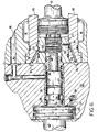
- Fig. 3 is a cross sectional view of the deceleration control mechanism, taken at 3 - 3 of Fig. 2.
- Fig. 4 is an enlarged cross sectional view of the deceleration control mechanism, taken at line 4 - 4 of Fig. 3.
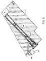
- Fig. 5 is a detailed cross sectional view, taken at 5 - 5 of Fig. 1.
- Fig. 6 is an enlarged view showing a portion of a deceleration control mechanism as illustrated in Fig. 2.
- Fig. 7 is a chart showing the gradual change of spool valve port area as a function of time after actuation of the deceleration control mechanism of the invention.
- Fig. 8 is a chart showing subsequent stage deceleration as a function of time.
- a two stage servo valve assembly 10 has a valve body 11 on which is mounted a first stage 12 or hydraulic amplifier.
- a first stage 12 has a housing 13 in which is positioned a torque motor 14 that has a flapper valve 15 that supplies proportional fluid pressures A 1 and A 2 through amplifier output channels 16 and 17.
- the fluid amplifier pressures A 1 and A 2 control a second stage 18 disposed within the valve body 11 below the first stage 12.
- a cylindrical sleeve or bushing 19 contains a servo valve spool 20, both of which are of a well-known design.
- the bushing has the number of output ports 21, which supply control fluid pressures C 1 , C 2 at controlled flow rates through respective control channels 22 and 23.
- the control pressures C 1 and C 2 are applied to a subsequent actuator stage, not shown.
- the pressures and flow rates appearing at the control output channels 22 and 23, depend on the positions of respective lands on the spool 20 and cooperating ports on the bushing 19 which communicate with a pressure chamber 24 and one or more return or drain chambers 25.
- the pressure chamber 24 is supplied with fluid pressure at high pressure while the return pressure R appearing at the return chambers is kept to a minimum.
- stub shafts 26 at left and right ends of the spool 20 which are fitted within respective inner bushings or sleeves 27.
- the stub shafts 26 serve as reciprocating pistons to position the spool 20 within the bushing 19.
- the amplifier channels 16 and 17 from the first stage 12 are coupled to the respective left and right ends of the spool 20, to wit, two outer faces of the stub shafts 26.
- a controlled disengagement valve assembly 30 is mounted on the left-hand side of the servo valve body 11, as shown in Fig. 2. Details of this mechanism are further illustrated with reference to Figs. 3, 4, 5, and 6.
- the controlled disengagement valve assembly 30 has an end-cap body 31 which attaches onto the left end of the valve body 11, and contains a fluid channel which, under normal conditions, functions to the same effect as the channel 29 of the end cap 28.
- the channel 32 normally communicates amplifier fluid pressure A 1 from the channel 16 to the left-side stub shaft 26.
- a spindle-type positioner 33 which is slidably mounted within a sleeve 34 or bushing that is, in turn, fitted within an axial bore in the body 31.
- a distal stem 35 on the positioner 33 protrudes to the right, in Figs. 2 and 4, to abut the position of the end face of the stubshaft 26.
- an amp port shutoff land 36 which opens or closes an amplifier port 37 of the sleeve 34.
- This port 37 communicates with the channel 32.
- the land 36 In an actuated or withdrawn position of the positioner 33, the land 36 is positioned proximally, i.e. to the left, of the amplifier port 37 and permits open flow of the amplifier fluid from the first stage 12, through the channels 16 and 32, to the piston face of the stub shaft 26.
- the land 36 obstructs the port 37 and thus cuts off the first stage hydraulic amplifier from this end of the spool.
- a positioner transition land 38 as better shown in Fig.
- a positioner transition orifice 39 in the sleeve 34 to admit flow of fluid pressure to or from an actuator piston 40 formed on the positioner 33.
- a positioner null orifice 41 communicates directly with a chamber of the piston 40. This positioner null orifice 41 is more restrictive than the positioner transition orifice 39.
- a positioner shaft 42 onto which are stacked a series of springs 43. These springs 43 are clamped down by a washer 44 that is in turn retained within a cup-shaped spring housing 45 that is bolted onto the body 31.
- a lock collar adjusting nut 46 is positioned on a projecting threaded end of the shaft 42. The lock collar nut 46 permits adjustment of final set position of the positioner.
- a metal cover 47 is secured onto the assembly 30 over the spring housing 45.
- the springs are selected so as to have a sufficient spring force to overcome the fluid force on the spool 20.
- an opening 48 in the stem 35 to communicate fluid pressure to the end of the stem through an axial bore.
- the sleeve 27 is provided with a spool transition port 49 which faces a spool transition land 50 at the proximal (left) end of the cooperating stub shaft 26. Fluid escaping from this through the spool transition port 49 passes through a spool transition orifice 51.
- This fluid which is at a pressure B 1 , then passes through a check valve 52, as shown in Fig. 3.
- the check valve is provided to prevent the spool transition port 49, land 50, and orifice 51 from interfering with normal operation of the servo valve.
- null override opening 53 provided at one or both sides of the stub shaft 26, and this communicates with another axial bore through to the piston face of the stub shaft 26.
- This null override opening 53 is guarded by a number of lands on the stub shaft 26.
- a null override port 54 in the sleeve 27 is in fluid communication with the null override opening 53 when the spool 20 approaches its null position.
- the port 54 is provided with a null override orifice 55 to permit flow of fluid at a controlled rate and at a pressure B 2 through the check valve 52 (Fig. 3).
- the null override orifice 55 is more restrictive than the spool transition orifice 51.
- the spool transition orifice 51 and spool null override orifice 53 communicate through a check valve 52 with the conduit 58.
- the check valve 52 permits fluid flow only when the pressure D is low, that is, only when the solenoid valve 59 is open.
- solenoid valve 59 is actuated closed, and the pressure D appearing in the conduit 58 is the supply pressure. Full fluid pressure is then applied to the positioner piston 40, and the piston force overcomes the force of the springs 43 and urges the positioner 33 to its open position. This allows unobstructed fluid communication between the first stage amplifier channel 16 and the left hand side of the spool 20.
- the solenoid 59 is deenergized, which reduces the pressure D in the conduit 58.
- the spring force from the springs 34 is then higher than the fluid force against the piston 40, and the springs 43 urge the positioner quickly to the closed position (i.e. to the right).
- the land 36 then obstructs the amp port 37 to disconnect the fluid path from the channels 16 and 32. If the spool 20 is in the position represented at the far left in Fig. 2, the positioner 33 is operative to push against the spool 20 so that stem 35 urges the stub shaft 26 rightward, until the spool 20 reaches its set position. Initially, fluid exits from the piston 40 through the positioner transitioner orifice 39. However, once the positioner transition land 38 has transisted sufficiently to cut off flow through this orifice 39, the remaining flow from the piston 40 is through the positioner null orifice 41 which is at a lower flow rate.
- the effect of this motion of the positioner 33 on the spool 20 is a gradual closing of the ports in the bushing 19 as the spool 20 moves towards its null position.
- the combined effect of the positioner transition and null override orifices is to yield a generally parabolic curve.
- the effect of this is to achieve as closely as possible a constant deceleration from the initiation of failure mode at a time T 0 until the spool 20 reaches it null position at a time T set .
- acceleration is kept below a maximum acceptable level.
- the positioner 33 will move to its closed position, as previously described. This cuts off the amplifier stage pressure from the amp channels 16 and 32 to the stub shaft 26. Fluid pressure remaining in amp channels 17 and 29 drives the stub shaft 26 and spool 20 towards the null position due to the pressure imbalance between the stub shaft ends. Fluid now begins to flow out through the spool transition orifice 51. Then, as the spool 20 approaches its null position, the spool transition land 50 cuts off flow through the orifice 51, and the fluid flow proceeds through the null override orifice 55. These two orifices 51 and 55 are selected so as to achieve control characteristics such as shown in Fig.
Landscapes
- Engineering & Computer Science (AREA)
- Physics & Mathematics (AREA)
- Fluid Mechanics (AREA)
- Mechanical Engineering (AREA)
- General Engineering & Computer Science (AREA)
- Servomotors (AREA)
- Fluid-Pressure Circuits (AREA)
Applications Claiming Priority (2)
| Application Number | Priority Date | Filing Date | Title |
|---|---|---|---|
| US07/877,530 US5197516A (en) | 1992-05-01 | 1992-05-01 | Hydraulic servo valve with controlled disengagement feature |
| US877530 | 1992-05-01 |
Publications (2)
| Publication Number | Publication Date |
|---|---|
| EP0578583A1 EP0578583A1 (en) | 1994-01-12 |
| EP0578583B1 true EP0578583B1 (en) | 1996-12-27 |
Family
ID=25370162
Family Applications (1)
| Application Number | Title | Priority Date | Filing Date |
|---|---|---|---|
| EP19930420174 Expired - Lifetime EP0578583B1 (en) | 1992-05-01 | 1993-04-27 | Hydraulic servo valve with controlled disengagement feature |
Country Status (5)
| Country | Link |
|---|---|
| US (1) | US5197516A (ja) |
| EP (1) | EP0578583B1 (ja) |
| JP (1) | JP3254037B2 (ja) |
| CA (1) | CA2095314C (ja) |
| DE (1) | DE69306870T2 (ja) |
Families Citing this family (7)
| Publication number | Priority date | Publication date | Assignee | Title |
|---|---|---|---|---|
| US6996982B2 (en) * | 2003-12-09 | 2006-02-14 | The United States Of America As Represented By The Administrator Of The Environmental Protection Agency | Method and device for switching hydraulic fluid supplies, such as for a hydraulic pump/motor |
| US7066710B2 (en) * | 2004-05-27 | 2006-06-27 | Honeywell International, Inc. | Pneumatic valve control having improved opening characteristics and an air turbine starter incorporating the same |
| US7147430B2 (en) * | 2004-06-10 | 2006-12-12 | Honeywell International, Inc. | Pneumatic valve control using downstream pressure feedback and an air turbine starter incorporating the same |
| US8464962B2 (en) * | 2005-02-22 | 2013-06-18 | Showerstart, Llc | 3-stage temperature control valve |
| GB201310452D0 (en) | 2013-06-12 | 2013-07-24 | Blagdon Actuation Res Ltd | Fluid Manifolds |
| WO2019112556A1 (en) | 2017-12-05 | 2019-06-13 | Flowserve Management Company | Position sensors for valve systems and related assemblies, systems and methods |
| US11851163B2 (en) | 2022-04-25 | 2023-12-26 | Hamilton Sundstrand Corporation | Hydraulically locking actuator configuration |
Family Cites Families (12)
| Publication number | Priority date | Publication date | Assignee | Title |
|---|---|---|---|---|
| US3228423A (en) * | 1956-01-23 | 1966-01-11 | Moog Servocontrols Inc | Fluid control valve in which a mechanical motion is transmitted from a dry region to a pressurized fluid filled region |
| US3078863A (en) * | 1957-04-12 | 1963-02-26 | Bell Aerospace Corp | Electro hydraulic servo device |
| US3221760A (en) * | 1957-04-12 | 1965-12-07 | Bell Aerospace Corp | Dry coil servo valve |
| US3712339A (en) * | 1970-11-10 | 1973-01-23 | Rexroth G Lohrer Eisenwerk Gmb | Regulating apparatus with throttle gaps |
| US3910314A (en) * | 1973-08-16 | 1975-10-07 | Koehring Co | High-speed shutoff and dump valve |
| US4046165A (en) * | 1975-06-04 | 1977-09-06 | Ibec Industries, Inc. | Valve-positioning apparatus |
| US4041983A (en) * | 1975-07-09 | 1977-08-16 | Caterpillar Tractor Co. | Pressure controlled swing valve with safety feature |
| DE2709445A1 (de) * | 1977-03-04 | 1978-09-07 | Hans W Dipl Ing Pongratz | Hydraulische daempfungseinrichtung mit hochpassverhalten fuer hydraulische servozylinder und -motoren |
| US4185660A (en) * | 1978-02-21 | 1980-01-29 | Consolidation Coal Company | Directional control valve |
| US4337797A (en) * | 1980-08-18 | 1982-07-06 | Moog Inc. | Bimetallic valve spool |
| US4456031A (en) * | 1982-05-03 | 1984-06-26 | Vickers, Incorporated | Electro-hydraulic servo valve system |
| US4617966A (en) * | 1983-12-01 | 1986-10-21 | Bardle Servovalve Co. | Electromagnetic positioner for a servovalve or the like |
-
1992
- 1992-05-01 US US07/877,530 patent/US5197516A/en not_active Expired - Lifetime
-
1993
- 1993-04-27 DE DE69306870T patent/DE69306870T2/de not_active Expired - Fee Related
- 1993-04-27 EP EP19930420174 patent/EP0578583B1/en not_active Expired - Lifetime
- 1993-04-30 JP JP10418193A patent/JP3254037B2/ja not_active Expired - Fee Related
- 1993-04-30 CA CA 2095314 patent/CA2095314C/en not_active Expired - Fee Related
Also Published As
| Publication number | Publication date |
|---|---|
| DE69306870T2 (de) | 1997-05-07 |
| EP0578583A1 (en) | 1994-01-12 |
| DE69306870D1 (de) | 1997-02-06 |
| US5197516A (en) | 1993-03-30 |
| JP3254037B2 (ja) | 2002-02-04 |
| JPH0610910A (ja) | 1994-01-21 |
| CA2095314C (en) | 1998-04-07 |
| CA2095314A1 (en) | 1993-11-02 |
Similar Documents
| Publication | Publication Date | Title |
|---|---|---|
| US6619183B2 (en) | Electrohydraulic valve assembly | |
| JP3710836B2 (ja) | フィードバックポッペト弁 | |
| US4572234A (en) | Hydraulic flow control valve | |
| EP0953776B1 (en) | Solenoid operated dual spool control valve | |
| US4456434A (en) | Power transmission | |
| US4201116A (en) | Electro-hydraulic proportional control servo valve | |
| US4348159A (en) | Convertible pump servo-valve control | |
| JP2744004B2 (ja) | 液圧制御装置 | |
| EP0761966B1 (en) | Pump displacement control for a variable displacement pump | |
| US4535966A (en) | Throttle valve | |
| US4903727A (en) | Safety valve | |
| EP0578583B1 (en) | Hydraulic servo valve with controlled disengagement feature | |
| US6220288B1 (en) | Electrohydraulic control device | |
| US6192928B1 (en) | Valve assembly | |
| US5996464A (en) | Fail safe valve and multiplexed fluid control systems incorporating the same | |
| EP0640047B1 (en) | Proportional control valve with pressure compensation | |
| US5174339A (en) | Fluid flow control valve | |
| US5253672A (en) | Hydraulic pressure control system | |
| US4345736A (en) | Solenoid operated valve and dashpot assembly | |
| US3587617A (en) | Fluid control apparatus | |
| US4682629A (en) | Electromagnetic proportional valves | |
| US6021876A (en) | Electrical proportional pressure control valve | |
| EP0231876B1 (en) | Hydraulic pressure control system | |
| JPS63130981A (ja) | 電磁式流量調整弁 | |
| GB2136055A (en) | Hydraulic Feed Circuits for Actuators |
Legal Events
| Date | Code | Title | Description |
|---|---|---|---|
| PUAI | Public reference made under article 153(3) epc to a published international application that has entered the european phase |
Free format text: ORIGINAL CODE: 0009012 |
|
| AK | Designated contracting states |
Kind code of ref document: A1 Designated state(s): DE FR GB |
|
| 17P | Request for examination filed |
Effective date: 19940623 |
|
| GRAG | Despatch of communication of intention to grant |
Free format text: ORIGINAL CODE: EPIDOS AGRA |
|
| 17Q | First examination report despatched |
Effective date: 19960329 |
|
| GRAH | Despatch of communication of intention to grant a patent |
Free format text: ORIGINAL CODE: EPIDOS IGRA |
|
| GRAH | Despatch of communication of intention to grant a patent |
Free format text: ORIGINAL CODE: EPIDOS IGRA |
|
| GRAH | Despatch of communication of intention to grant a patent |
Free format text: ORIGINAL CODE: EPIDOS IGRA |
|
| GRAA | (expected) grant |
Free format text: ORIGINAL CODE: 0009210 |
|
| AK | Designated contracting states |
Kind code of ref document: B1 Designated state(s): DE FR GB |
|
| ET | Fr: translation filed | ||
| REF | Corresponds to: |
Ref document number: 69306870 Country of ref document: DE Date of ref document: 19970206 |
|
| REG | Reference to a national code |
Ref country code: FR Ref legal event code: TP Ref country code: FR Ref legal event code: CD |
|
| PLBE | No opposition filed within time limit |
Free format text: ORIGINAL CODE: 0009261 |
|
| STAA | Information on the status of an ep patent application or granted ep patent |
Free format text: STATUS: NO OPPOSITION FILED WITHIN TIME LIMIT |
|
| 26N | No opposition filed | ||
| PGFP | Annual fee paid to national office [announced via postgrant information from national office to epo] |
Ref country code: FR Payment date: 19980428 Year of fee payment: 6 |
|
| PG25 | Lapsed in a contracting state [announced via postgrant information from national office to epo] |
Ref country code: FR Free format text: LAPSE BECAUSE OF NON-PAYMENT OF DUE FEES Effective date: 19991231 |
|
| REG | Reference to a national code |
Ref country code: FR Ref legal event code: ST |
|
| REG | Reference to a national code |
Ref country code: GB Ref legal event code: IF02 |
|
| PGFP | Annual fee paid to national office [announced via postgrant information from national office to epo] |
Ref country code: DE Payment date: 20040506 Year of fee payment: 12 |
|
| PGFP | Annual fee paid to national office [announced via postgrant information from national office to epo] |
Ref country code: GB Payment date: 20040514 Year of fee payment: 12 |
|
| PG25 | Lapsed in a contracting state [announced via postgrant information from national office to epo] |
Ref country code: GB Free format text: LAPSE BECAUSE OF NON-PAYMENT OF DUE FEES Effective date: 20050427 |
|
| PG25 | Lapsed in a contracting state [announced via postgrant information from national office to epo] |
Ref country code: DE Free format text: LAPSE BECAUSE OF NON-PAYMENT OF DUE FEES Effective date: 20051101 |
|
| GBPC | Gb: european patent ceased through non-payment of renewal fee |
Effective date: 20050427 |