EP0578184A1 - Digital copying machine - Google Patents
Digital copying machine Download PDFInfo
- Publication number
- EP0578184A1 EP0578184A1 EP93110740A EP93110740A EP0578184A1 EP 0578184 A1 EP0578184 A1 EP 0578184A1 EP 93110740 A EP93110740 A EP 93110740A EP 93110740 A EP93110740 A EP 93110740A EP 0578184 A1 EP0578184 A1 EP 0578184A1
- Authority
- EP
- European Patent Office
- Prior art keywords
- data
- copying machine
- memory
- digital copying
- image
- Prior art date
- Legal status (The legal status is an assumption and is not a legal conclusion. Google has not performed a legal analysis and makes no representation as to the accuracy of the status listed.)
- Granted
Links
- 238000007639 printing Methods 0.000 claims abstract description 10
- 238000012545 processing Methods 0.000 description 39
- 238000009792 diffusion process Methods 0.000 description 13
- 238000000034 method Methods 0.000 description 11
- 230000002194 synthesizing effect Effects 0.000 description 6
- 238000012546 transfer Methods 0.000 description 4
- 238000012937 correction Methods 0.000 description 3
- 230000000694 effects Effects 0.000 description 3
- 238000004891 communication Methods 0.000 description 2
- 238000010586 diagram Methods 0.000 description 2
- 230000006870 function Effects 0.000 description 2
- 238000011282 treatment Methods 0.000 description 2
- 238000006243 chemical reaction Methods 0.000 description 1
- 238000004140 cleaning Methods 0.000 description 1
- 230000006835 compression Effects 0.000 description 1
- 238000007906 compression Methods 0.000 description 1
- 238000010276 construction Methods 0.000 description 1
- 238000001514 detection method Methods 0.000 description 1
- 238000007599 discharging Methods 0.000 description 1
- 238000010304 firing Methods 0.000 description 1
- 239000011521 glass Substances 0.000 description 1
- 230000004044 response Effects 0.000 description 1
- 230000002441 reversible effect Effects 0.000 description 1
- 239000004065 semiconductor Substances 0.000 description 1
- 230000001360 synchronised effect Effects 0.000 description 1
Images


Classifications
-
- H—ELECTRICITY
- H04—ELECTRIC COMMUNICATION TECHNIQUE
- H04N—PICTORIAL COMMUNICATION, e.g. TELEVISION
- H04N1/00—Scanning, transmission or reproduction of documents or the like, e.g. facsimile transmission; Details thereof
- H04N1/32—Circuits or arrangements for control or supervision between transmitter and receiver or between image input and image output device, e.g. between a still-image camera and its memory or between a still-image camera and a printer device
- H04N1/32101—Display, printing, storage or transmission of additional information, e.g. ID code, date and time or title
- H04N1/32106—Display, printing, storage or transmission of additional information, e.g. ID code, date and time or title separate from the image data, e.g. in a different computer file
- H04N1/32112—Display, printing, storage or transmission of additional information, e.g. ID code, date and time or title separate from the image data, e.g. in a different computer file in a separate computer file, document page or paper sheet, e.g. a fax cover sheet
-
- H—ELECTRICITY
- H04—ELECTRIC COMMUNICATION TECHNIQUE
- H04N—PICTORIAL COMMUNICATION, e.g. TELEVISION
- H04N1/00—Scanning, transmission or reproduction of documents or the like, e.g. facsimile transmission; Details thereof
- H04N1/387—Composing, repositioning or otherwise geometrically modifying originals
- H04N1/3872—Repositioning or masking
- H04N1/3873—Repositioning or masking defined only by a limited number of coordinate points or parameters, e.g. corners, centre; for trimming
- H04N1/3875—Repositioning or masking defined only by a limited number of coordinate points or parameters, e.g. corners, centre; for trimming combined with enlarging or reducing
-
- H—ELECTRICITY
- H04—ELECTRIC COMMUNICATION TECHNIQUE
- H04N—PICTORIAL COMMUNICATION, e.g. TELEVISION
- H04N2201/00—Indexing scheme relating to scanning, transmission or reproduction of documents or the like, and to details thereof
- H04N2201/32—Circuits or arrangements for control or supervision between transmitter and receiver or between image input and image output device, e.g. between a still-image camera and its memory or between a still-image camera and a printer device
- H04N2201/3201—Display, printing, storage or transmission of additional information, e.g. ID code, date and time or title
- H04N2201/3202—Display, printing, storage or transmission of additional information, e.g. ID code, date and time or title of communication or activity log or report
-
- H—ELECTRICITY
- H04—ELECTRIC COMMUNICATION TECHNIQUE
- H04N—PICTORIAL COMMUNICATION, e.g. TELEVISION
- H04N2201/00—Indexing scheme relating to scanning, transmission or reproduction of documents or the like, and to details thereof
- H04N2201/32—Circuits or arrangements for control or supervision between transmitter and receiver or between image input and image output device, e.g. between a still-image camera and its memory or between a still-image camera and a printer device
- H04N2201/3201—Display, printing, storage or transmission of additional information, e.g. ID code, date and time or title
- H04N2201/3212—Display, printing, storage or transmission of additional information, e.g. ID code, date and time or title of data relating to a job, e.g. communication, capture or filing of an image
- H04N2201/3221—Display, printing, storage or transmission of additional information, e.g. ID code, date and time or title of data relating to a job, e.g. communication, capture or filing of an image of a job number or identification, e.g. communication number
-
- H—ELECTRICITY
- H04—ELECTRIC COMMUNICATION TECHNIQUE
- H04N—PICTORIAL COMMUNICATION, e.g. TELEVISION
- H04N2201/00—Indexing scheme relating to scanning, transmission or reproduction of documents or the like, and to details thereof
- H04N2201/32—Circuits or arrangements for control or supervision between transmitter and receiver or between image input and image output device, e.g. between a still-image camera and its memory or between a still-image camera and a printer device
- H04N2201/3201—Display, printing, storage or transmission of additional information, e.g. ID code, date and time or title
- H04N2201/3225—Display, printing, storage or transmission of additional information, e.g. ID code, date and time or title of data relating to an image, a page or a document
- H04N2201/3226—Display, printing, storage or transmission of additional information, e.g. ID code, date and time or title of data relating to an image, a page or a document of identification information or the like, e.g. ID code, index, title, part of an image, reduced-size image
-
- H—ELECTRICITY
- H04—ELECTRIC COMMUNICATION TECHNIQUE
- H04N—PICTORIAL COMMUNICATION, e.g. TELEVISION
- H04N2201/00—Indexing scheme relating to scanning, transmission or reproduction of documents or the like, and to details thereof
- H04N2201/32—Circuits or arrangements for control or supervision between transmitter and receiver or between image input and image output device, e.g. between a still-image camera and its memory or between a still-image camera and a printer device
- H04N2201/3201—Display, printing, storage or transmission of additional information, e.g. ID code, date and time or title
- H04N2201/3271—Printing or stamping
-
- H—ELECTRICITY
- H04—ELECTRIC COMMUNICATION TECHNIQUE
- H04N—PICTORIAL COMMUNICATION, e.g. TELEVISION
- H04N2201/00—Indexing scheme relating to scanning, transmission or reproduction of documents or the like, and to details thereof
- H04N2201/32—Circuits or arrangements for control or supervision between transmitter and receiver or between image input and image output device, e.g. between a still-image camera and its memory or between a still-image camera and a printer device
- H04N2201/3201—Display, printing, storage or transmission of additional information, e.g. ID code, date and time or title
- H04N2201/3274—Storage or retrieval of prestored additional information
-
- H—ELECTRICITY
- H04—ELECTRIC COMMUNICATION TECHNIQUE
- H04N—PICTORIAL COMMUNICATION, e.g. TELEVISION
- H04N2201/00—Indexing scheme relating to scanning, transmission or reproduction of documents or the like, and to details thereof
- H04N2201/32—Circuits or arrangements for control or supervision between transmitter and receiver or between image input and image output device, e.g. between a still-image camera and its memory or between a still-image camera and a printer device
- H04N2201/3285—Circuits or arrangements for control or supervision between transmitter and receiver or between image input and image output device, e.g. between a still-image camera and its memory or between a still-image camera and a printer device using picture signal storage, e.g. at transmitter
- H04N2201/3288—Storage of two or more complete document pages or image frames
Definitions
- the present invention relates to a digital copying machine, and more particularly to the digital copying machine in which a facsimile apparatus is built.
- the received data is stored in a memory and is output for printing it as it is.
- the present invention is characterized by including a facsimile apparatus, a memory for storing all the data received by said facsimile apparatus, and a printer apparatus for selectively printing data corresponding to only a cover page of data stored in said memory.
- the printer apparatus operates to selectively print data corresponding to only a cover page of all the data stored in the memory. Hence, only a desired data is easily selected for outputting. This results in saving paper and reducing the output time and easily and quickly knowing the summary of the desired data.
- the printer facsimile operates to selectively print the data corresponding to only a cover page of each data item stored in the memory. Hence, it provides a capability of easily selecting only the desired data and outputting it, for the purpose of saving paper, reducing the output time, and quickly obtaining the summary of the desired data item.
- Fig. 1 is a block diagram showing an image processing unit and control systems included in a digital copying machine according to an embodiment of the present invention.
- Fig. 2 is a sectional view showing an overall arrangement of a digital copying machine according to an embodiment of the present invention.
- Fig. 3 is a view showing an essential part of a fixing device.
- Fig. 4 is a view for explaining an operation panel.
- Fig. 5 is a view showing an initial screen appearing on the operation panel when the received data is stored.
- Fig. 6 is a view showing an output format example at a cover page output mode.
- Fig. 7 is a flowchart for explaining a first operation to be done in the digital copying machine according to the embodiment of the present invention.
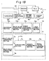
- Fig. 8 is a flowchart for explaining the second operation to be done in the digital copying machine according to the embodiment of the present invention.
- Fig. 2 is a sectional view showing the overall arrangement of the embodiment of the digital copying machine arranged to have a paper conveying device and form an image on both sides of one paper.
- a digital copying machine 30 provides a scanner 31, a laser printer 32, a multi-stage paper feeder 33 and a sorter 34.
- the scanner 31 is arranged of a document platform 35 made of transparent glass, a reversible automatic document feeder (RDF) 36, and a scanner unit 40.
- a document platform 35 made of transparent glass
- RDF reversible automatic document feeder
- the multi-stage paper feeder 33 includes a first cassette 51, a second cassette 52, a third cassette 53, and a fourth cassette 55 to be selectively added.
- the multi-stage paper feeder 33 operates to feed the papers held in the cassette at each stage from the top paper one by one and convey the paper to the laser printer 32.
- the RDF 36 is arranged to automatically feed to the scanner unit 40 a plurality of papers set by one operation one by one.
- the scanner unit 40 operates to read one side or both sides of the paper according to an operator's selection.
- the scanner unit 40 includes a lamp reflector assembly 41 for exposing the document, a plurality of reflective mirrors 43 for guiding a reflective light image from the document to a photoconductive converting element (Charge Coupled Device: CCD) 42, and a lens 44 for forming the reflective light image on the CCD 42.
- CCD Charge Coupled Device
- the scanner 31 is arranged to read the image of the document as the scanner unit 40 is traveling along the lower side of the document platform 35.
- the scanner 31 is arranged to read the document image as the document is being conveyed in the state that the scanner unit 40 is stopped at a predetermined location lower than the RDF 36.
- the image data obtained by reading the document image through the effect of the scanner unit 40 is sent to an image processing unit in which various treatments are performed with respect to the image data. Then, the resulting image data is temporarily stored in the memory included in the image processing unit so that the image data stored in the memory may be sent to the laser printer 32 for forming an image on paper according to an indication for output.
- the laser printer 32 provides a manual document tray 45, a laser writing unit 46 and an electronic photography process section 47 for forming an image.
- the laser writing unit 46 includes a semiconductor laser for firing a laser beam formed according to the image data stored in the memory, a polygon mirror for deflecting the laser beam at an equal angular speed, and an f- ⁇ lens for amending the deflected laser beam in a manner to deflect the laser beam on a photosensitive drum 48 of the electronic photography process unit 47 at an equal angular speed.
- the electronic photography process unit 47 includes the photosensitive drum 48 around which a charging device, a developing device, a transfer device, a stripping device, a cleaning device, a discharging device and a fixing device 49 are located.
- a convey path 50 is provided in the downward side of the conveying direction of a sheet of paper on which an image is to be formed rather than the fixing device 49.
- the convey path 50 is branched into a convey path 57 leading to the sorter 34 and a convey path 58 leading to a multi-stage paper feeding unit 33.
- the convey path 58 is branched at the multi-stage paper feeding unit 33. As the convey path after the branch point, a reversing convey path 50a and a double side/synthesizing convey path 50b are provided.
- the reversing convey path 50a is a convey path for revering a rear surface of the paper at a double side copying mode for copying both sides of one paper.
- the double side/synthesizing convey path 50b is a convey path formed to convey a paper from the reversing convey path 50a to an image forming point of the photosensitive drum 48 at the double side copying mode or convey the paper to the image forming point of the photosensitive drum 48 without being reversed at a one side synthesizing copying mode for forming different images on one side of the paper for forming a image with different color toners.
- the multi-stage paper feeding unit 33 includes a common convey path 56, which is constructed to convey papers from the first cassette 51, the second cassette 52, and the third cassette 53 to the electronic photography process unit 47.
- the common convey path 56 is connected to the convey path 59 led from the fourth cassette 55 on the way to the electronic photography process unit 47 and then leads to a convey path 60.
- the convey path 60 is formed to connect to a connecting point 62 with a convey path 61 led from the double side/synthesizing convey path 50b and the manual document tray 45 and to lead to an image forming location between the photosensitive drum 48 of the electronic photography process unit 47 and the transfer device.
- the connecting point 62 for connecting these three convey paths is provided closer to the image forming location.
- the laser writing unit 46 operates to scan a laser beam on the surface of the photosensitive drum 48 for forming the image data read out of the memory as an electrostatic latent image.
- a toner image visualized with toner is electrostatically transferred and fixed on one side of the paper conveyed from the multi-stage paper feeding unit 33.
- the paper on which the image is formed is conveyed from the fixing device 49 to the sorter 34 through the convey paths 50 and 57 or to the reversing convey path 50a through the convey paths 50 and 58.
- Fig. 1 is a block diagram showing an image processing unit and various control systems included in the copying machine 30 shown in Fig. 2.
- the image processing unit included in the copying machine 30 provides an image data input unit 70, an image processing section 71, an image data output section 72, a memory 73 arranged of a RAM (Random Access Memory) and so on, and a central processing unit (CPU) 74 for processing an image.
- an image data input unit 70 an image processing section 71, an image data output section 72, a memory 73 arranged of a RAM (Random Access Memory) and so on, and a central processing unit (CPU) 74 for processing an image.
- CPU central processing unit
- the image data input unit 70 includes a CCD section 70a, a histogram processing section 70b and an error diffusion processing section 70c.
- the image data input unit 70 operates to convert the image data of the document read from the CCD 42 shown in Fig. 2 into the binary data, process the image data through the effect of the error diffusion method as forming a histogram of the data as a binary digital amount, and temporarily store the processed image data in the memory 73.
- the CCD section 70a operates to analog-to-digital convert an analog electric signal formed according to each pixel density of the image data into the digital signal, perform an MTF correction, a monochrome correction or a gamma correction with respect to the digital signal, and output the processed signal to the histogram processing section 70b as a digital 256-tone (8 bit) signal.
- the histogram processing section 70b operates to add the digital signal output from the CCD section 70a at each of 256-tone pixel densities for obtaining density information (histogram data) and send the obtained histogram data to the CPU 74 if necessary or send it to the error diffusion Processing section 70c as the pixel data.
- the error diffusion processing section 70c operates to convert a digital signal of 8 bit/pixel output from the CCD section 70a into one bit (binary) signal through the effect of the error diffusion method which is one kind of a pseudo halftone processing, that is, the method for reflecting an error concerned with conversion of the data into the binary determination of the adjacent pixel. Then, the binary data is subject to a redistributing operation for representing a local area density on the document with fidelity.
- the image processing unit 71 includes multi-value converting sections 71a and 71b, a synthesizing section 71c, a density converting section 71d, a scale factor changing section 71e, an image processing section 71f, an error diffusion processing section 71g, and a compressing section 71h.
- the image processing unit 71 is a processing unit for converting the input image data into the final image data desired by an operator. Until the final output image data is stored in the memory 73, the image data is being processed in this processing section.
- the foregoing processing sections included in the image processing unit 71 are operated if necessary. In some cases, they may not be operated.
- the data converted into the binary data in the error diffusion processing section 70c is converted into 256 tones again.
- the synthesizing section 71c operates to selectively perform a logic operation for each pixel, such as a logic OR, a logic AND or an exclusive OR.
- the data to be operated is pixel data stored in the memory 73 and bit data sent from a pattern generator (PG).
- the density converting section 71d operates to optionally set a relation between an input density and an output density with respect to data signals of 256 tones, based on a predetermined tone converting table.
- the scale factor changing section 71e operates to perform an interpolation with respect to the input known data according to an indicated scale factor, for deriving pixel data (density value) against the scale factor changed pixel and changing the scale factor of the main scan after changing the scale factor of the sub scan.
- the image process section 71f operates to perform various image treatments with respect to the input pixel data or collect the information such as features with respect to a data train.
- the error diffusion processing section 71g performs the same processing as the error diffusion processing section 70c included in the image data input unit 70.
- the compressing section 71h operates to compress the binary data by means of a coding operation referred to as run length coding. Moreover, with respect to compression of the image data, the compressing operation operates in the final processing loop when the final output image data is completed.
- the image data output unit 72 includes a restoring section 72a, a multi-value converting section 72b, an error diffusion processing section 72c, and a laser output section 72d.
- the image data output unit 72 operates to restore the compressed image stored in the memory 73 for converting it to the original 256-tone image data, perform an error diffusion about quadruple data for achieving a smoother halftone representation than the binary data, and transfer the data to the laser output section 72d.
- the restoring section 72a serves to restore the image data compressed by the compressing section 71h.
- the multi-value converting section 72b serves to perform the same processing as the multi-value converting sections 71a and 71b included in the image processing unit 71.
- the error diffusion processing section 72c serves to perform the same processing as the error diffusion processing section 70c included in the image data processing unit 70.
- the laser output section 72d operates to convert the digital pixel data into an on/off signal of a laser for switching on and off the laser, based on the control signal sent from a CPU 79 for controlling the printer
- the data to be processed in the image data input unit 70 and the image data output unit 72 is basically stored in the memory 73 in the form of binary data, for reducing the amount of the memory 73.
- the data may be quadruple data if the inferiority of the image data is considered.
- the CPU 74 for processing an image being connected to the memory is connected to the CPU 79 through a communication line 84.
- a facsimile apparatus In a facsimile apparatus, on the other hand, when the information is received from a calling facsimile apparatus through a phone line 78, an NCU 77, and a modem 76, the receipt signal is sent to the CPU 79 for controlling the printer unit. In response, the CPU 79 gives an order for preparing a memory for the image data (data sent from the modem) to the CPU 74 for processing an image through the communication line 84 so that the image data may be stored in the memory 73 through the data line 85.
- the image data is read out of the memory 73.
- the laser writing unit 46 is driven so that an electrostatic latent image corresponding to the received information may be formed on the surface of the photosensitive drum 48.
- the surface of the photosensitive drum 48 is uniformly charged.
- the developing device serves to feed toner onto the electrostatic latent image formed on the photosensitive drum 48 so that a toner image may be formed on the corresponding portion of the surface.
- the CPU 79 for controlling the printer as shown in Fig. 1 operates to feed a sheet of paper and drive the convey roller so as to feed the sheets of paper in the cassette to a resist roller 63.
- the resist roller 63 operates to feed a sheet of paper between the photosensitive drum 48 and a transfer charger in synchronous to the rotation of the photosensitive drum 48. With this operation, the toner image on the photosensitive drum 48 is transferred onto the sheet of paper.
- the paper on which the toner image is transferred is conveyed to the location where the fixing device 49 is. At this location, the fixing process is carried out with respect to the image-transferred paper. Then, the resulting paper is sent to the sorter 34 through the convey paths 50 and 57 and then to the reversing convey path 50a through the convey paths 50 and 58.
- Fig. 3 shows the detail of the fixing device 49.
- the fixing device 49 includes a pair of rollers consisting of an upper roller 100a and a lower roller 100b. Inside of the upper roller 100a, a heater lamp 101 is provided to heat the surface of the upper roller 100a up to a fixing temperature.
- a thermistor 102 is provided inside of the upper roller 100a for detecting the temperature of the surface of the upper roller 100a.
- the thermistor 102 is supported by a spring device 103 in a manner to allow the thermistor 102 to constantly contact with the upper roller 100a with uniform pressure.
- the thermistor 102 operates to output a voltage signal corresponding to the surface temperature of the upper roller 100a to the CPU 79 for controlling the printer. With this voltage signal, the CPU 79 for controlling the printer operates to issue a predetermined driving signal to a heater ON-OFF driving circuit 80 in a manner to set the surface temperature of the upper roller 100a to a fixing temperature by comparing the detection signal sent from the thermistor 102 and the reference voltage value.
- the heater ON-OFF circuit 80 is equipped with a triac which uses a zero cross. In accordance with a driving signal sent from the CPU 79 for controlling the printer, the heater lamp 101 is heated so as to set the upper roller 100a, that is, the fixing device 49 to the fixing temperature.
- a real-time clock 82 connected to a battery power source 83.
- This IC is backed up by the battery irrespective of the ON-OFF of the power source 83 and operates to count the time.
- Fig. 7 only at a night back-up mode (7-2) in the state of a facsimile mode (7-1), the received data of the facsimile is stored as image data in the memory (7-4).
- the copying machine When the power source of the printer is switched on (7-5), the copying machine enters into a warm-up state so that the heater lamp may be switched on for adjusting the temperature (7-6).
- the printer power source is turned on, if no data is stored in the memory (7-7), after the ON-OFF control of the heater lamp is executed (7-3), an initial screen at the normal mode is displayed on an operation panel (7-11).
- the number of papers and the number of data items stored in the memory is displayed on the operation panel 202 (see Fig. 4) (7-8).
- Fig. 5 appears on the operation panel 202 shown in Fig. 4.
- 200 denotes a switch for switching the night facsimile mode to the normal mode or vice versa.
- 201 denotes template keys.
- 202 denotes a display panel.
- 203 denotes an interrupt key.
- 204 denotes a clear key.
- 205 denotes a copy button.
- any one of the contents 1 to 5 may be selected for output.
- the display page output 211 of this screen is selected and the predetermined temperature is achieved for fixing (7-9)
- the copy button 205 is pressed in a copy standby state (7-10).
- the CPU 74 for processing image serves to operate an output scale factor by referring to the number of data items stored in the memory, the size of the paper, and the number of the papers, automatically set a scale factor according to the size of paper (for example, A3) (no magnification) (8-2), and output the cover data pieces 220 to 224 numbered at the predetermined locations in the output form of the cover page output mode (8-5).
- a memory number is automatically output. From this memory number, the content included in any number of facsimile data may be understood. This numbering is equal to that on the operation panel.
- the data content is numbered in the earlier sequence of the transmitting time of the facsimile when it is output.
- a scale factor (reducing factor) of the data to be output when outputting a cover page is smaller than a certain value (for example, in a case of 25% or less, 8-3)
- the operation is executed to increase the number of such papers as keeping the scale factor higher than a certain value (executed by the CPU 79 for controlling the printer).
- the scale factor of the data is larger than 25%, the memory NO and the cover data are output at any scale factor.
- the image is allowed to be output by pressing the copy button without having to select any mode (8-4).
Abstract
Description
- The present invention relates to a digital copying machine, and more particularly to the digital copying machine in which a facsimile apparatus is built.
- In a general digital copying machine having a facsimile apparatus, the received data is stored in a memory and is output for printing it as it is.
- When data corresponding to a plurality of pages is stored in a memory, it takes a long time to output all the received data.
- Further, though only one piece of data is viewed, if a plurality of pieces of data are received before the subject piece of data, it takes a considerably long time to output the subject piece of data and consumes a great deal of papers to do so.
- It is therefore an object of the present invention to provide a digital copying machine having a facsimile apparatus built therein which is capable of outputting the data corresponding to only a cover paper of the received data selectivity.
- The present invention is characterized by including a facsimile apparatus, a memory for storing all the data received by said facsimile apparatus, and a printer apparatus for selectively printing data corresponding to only a cover page of data stored in said memory.
- The printer apparatus operates to selectively print data corresponding to only a cover page of all the data stored in the memory. Hence, only a desired data is easily selected for outputting. This results in saving paper and reducing the output time and easily and quickly knowing the summary of the desired data.
- Further objects and advantages of the present invention will be apparent from the following description of the preferred embodiments of the invention as illustrated in the accompanying drawings.
- The printer facsimile operates to selectively print the data corresponding to only a cover page of each data item stored in the memory. Hence, it provides a capability of easily selecting only the desired data and outputting it, for the purpose of saving paper, reducing the output time, and quickly obtaining the summary of the desired data item.
- Fig. 1 is a block diagram showing an image processing unit and control systems included in a digital copying machine according to an embodiment of the present invention.
- Fig. 2 is a sectional view showing an overall arrangement of a digital copying machine according to an embodiment of the present invention.
- Fig. 3 is a view showing an essential part of a fixing device.
- Fig. 4 is a view for explaining an operation panel.
- Fig. 5 is a view showing an initial screen appearing on the operation panel when the received data is stored.
- Fig. 6 is a view showing an output format example at a cover page output mode.
- Fig. 7 is a flowchart for explaining a first operation to be done in the digital copying machine according to the embodiment of the present invention.
- Fig. 8 is a flowchart for explaining the second operation to be done in the digital copying machine according to the embodiment of the present invention.
- The description will be oriented to a digital copying machine according to an embodiment of the present invention as referring to the drawings.
- Fig. 2 is a sectional view showing the overall arrangement of the embodiment of the digital copying machine arranged to have a paper conveying device and form an image on both sides of one paper.
- As shown in Fig. 2, a
digital copying machine 30 provides ascanner 31, alaser printer 32, amulti-stage paper feeder 33 and asorter 34. - The
scanner 31 is arranged of adocument platform 35 made of transparent glass, a reversible automatic document feeder (RDF) 36, and ascanner unit 40. - The
multi-stage paper feeder 33 includes afirst cassette 51, asecond cassette 52, athird cassette 53, and afourth cassette 55 to be selectively added. - The
multi-stage paper feeder 33 operates to feed the papers held in the cassette at each stage from the top paper one by one and convey the paper to thelaser printer 32. - The
RDF 36 is arranged to automatically feed to the scanner unit 40 a plurality of papers set by one operation one by one. Thescanner unit 40 operates to read one side or both sides of the paper according to an operator's selection. - The
scanner unit 40 includes alamp reflector assembly 41 for exposing the document, a plurality ofreflective mirrors 43 for guiding a reflective light image from the document to a photoconductive converting element (Charge Coupled Device: CCD) 42, and alens 44 for forming the reflective light image on theCCD 42. - To scan the document placed on the
document platform 35, thescanner 31 is arranged to read the image of the document as thescanner unit 40 is traveling along the lower side of thedocument platform 35. In the case of using theRDF 36, thescanner 31 is arranged to read the document image as the document is being conveyed in the state that thescanner unit 40 is stopped at a predetermined location lower than theRDF 36. - The image data obtained by reading the document image through the effect of the
scanner unit 40 is sent to an image processing unit in which various treatments are performed with respect to the image data. Then, the resulting image data is temporarily stored in the memory included in the image processing unit so that the image data stored in the memory may be sent to thelaser printer 32 for forming an image on paper according to an indication for output. - The
laser printer 32 provides amanual document tray 45, alaser writing unit 46 and an electronicphotography process section 47 for forming an image. - The
laser writing unit 46 includes a semiconductor laser for firing a laser beam formed according to the image data stored in the memory, a polygon mirror for deflecting the laser beam at an equal angular speed, and an f-ϑ lens for amending the deflected laser beam in a manner to deflect the laser beam on aphotosensitive drum 48 of the electronicphotography process unit 47 at an equal angular speed. - The electronic
photography process unit 47 includes thephotosensitive drum 48 around which a charging device, a developing device, a transfer device, a stripping device, a cleaning device, a discharging device and afixing device 49 are located. - A
convey path 50 is provided in the downward side of the conveying direction of a sheet of paper on which an image is to be formed rather than thefixing device 49. Theconvey path 50 is branched into aconvey path 57 leading to thesorter 34 and aconvey path 58 leading to a multi-stagepaper feeding unit 33. - The
convey path 58 is branched at the multi-stagepaper feeding unit 33. As the convey path after the branch point, a reversing conveypath 50a and a double side/synthesizing conveypath 50b are provided. - The reversing convey
path 50a is a convey path for revering a rear surface of the paper at a double side copying mode for copying both sides of one paper. - The double side/synthesizing
convey path 50b is a convey path formed to convey a paper from the reversing conveypath 50a to an image forming point of thephotosensitive drum 48 at the double side copying mode or convey the paper to the image forming point of thephotosensitive drum 48 without being reversed at a one side synthesizing copying mode for forming different images on one side of the paper for forming a image with different color toners. - The multi-stage
paper feeding unit 33 includes acommon convey path 56, which is constructed to convey papers from thefirst cassette 51, thesecond cassette 52, and thethird cassette 53 to the electronicphotography process unit 47. - The
common convey path 56 is connected to theconvey path 59 led from thefourth cassette 55 on the way to the electronicphotography process unit 47 and then leads to aconvey path 60. - The
convey path 60 is formed to connect to aconnecting point 62 with aconvey path 61 led from the double side/synthesizingconvey path 50b and themanual document tray 45 and to lead to an image forming location between thephotosensitive drum 48 of the electronicphotography process unit 47 and the transfer device. The connectingpoint 62 for connecting these three convey paths is provided closer to the image forming location. - In the
laser writing unit 46 and the electronicphotography process unit 47, therefore, thelaser writing unit 46 operates to scan a laser beam on the surface of thephotosensitive drum 48 for forming the image data read out of the memory as an electrostatic latent image. A toner image visualized with toner is electrostatically transferred and fixed on one side of the paper conveyed from the multi-stagepaper feeding unit 33. The paper on which the image is formed is conveyed from thefixing device 49 to thesorter 34 through theconvey paths path 50a through theconvey paths - Next, the description will be oriented to the construction and the function of the image processing unit included in the
copying machine 30. - Fig. 1 is a block diagram showing an image processing unit and various control systems included in the
copying machine 30 shown in Fig. 2. - The image processing unit included in the
copying machine 30 provides an imagedata input unit 70, animage processing section 71, an imagedata output section 72, a memory 73 arranged of a RAM (Random Access Memory) and so on, and a central processing unit (CPU) 74 for processing an image. - The image
data input unit 70 includes aCCD section 70a, ahistogram processing section 70b and an errordiffusion processing section 70c. - The image
data input unit 70 operates to convert the image data of the document read from theCCD 42 shown in Fig. 2 into the binary data, process the image data through the effect of the error diffusion method as forming a histogram of the data as a binary digital amount, and temporarily store the processed image data in the memory 73. - That is, the
CCD section 70a operates to analog-to-digital convert an analog electric signal formed according to each pixel density of the image data into the digital signal, perform an MTF correction, a monochrome correction or a gamma correction with respect to the digital signal, and output the processed signal to thehistogram processing section 70b as a digital 256-tone (8 bit) signal. - The
histogram processing section 70b operates to add the digital signal output from theCCD section 70a at each of 256-tone pixel densities for obtaining density information (histogram data) and send the obtained histogram data to theCPU 74 if necessary or send it to the errordiffusion Processing section 70c as the pixel data. - The error
diffusion processing section 70c operates to convert a digital signal of 8 bit/pixel output from theCCD section 70a into one bit (binary) signal through the effect of the error diffusion method which is one kind of a pseudo halftone processing, that is, the method for reflecting an error concerned with conversion of the data into the binary determination of the adjacent pixel. Then, the binary data is subject to a redistributing operation for representing a local area density on the document with fidelity. - The
image processing unit 71 includesmulti-value converting sections 71a and 71b, asynthesizing section 71c, adensity converting section 71d, a scalefactor changing section 71e, animage processing section 71f, an errordiffusion processing section 71g, and acompressing section 71h. - The
image processing unit 71 is a processing unit for converting the input image data into the final image data desired by an operator. Until the final output image data is stored in the memory 73, the image data is being processed in this processing section. The foregoing processing sections included in theimage processing unit 71 are operated if necessary. In some cases, they may not be operated. - That is, in the
multi-value converting sections 71a and 71b, the data converted into the binary data in the errordiffusion processing section 70c is converted into 256 tones again. - The synthesizing
section 71c operates to selectively perform a logic operation for each pixel, such as a logic OR, a logic AND or an exclusive OR. The data to be operated is pixel data stored in the memory 73 and bit data sent from a pattern generator (PG). - The
density converting section 71d operates to optionally set a relation between an input density and an output density with respect to data signals of 256 tones, based on a predetermined tone converting table. - The scale
factor changing section 71e operates to perform an interpolation with respect to the input known data according to an indicated scale factor, for deriving pixel data (density value) against the scale factor changed pixel and changing the scale factor of the main scan after changing the scale factor of the sub scan. - The
image process section 71f operates to perform various image treatments with respect to the input pixel data or collect the information such as features with respect to a data train. - The error
diffusion processing section 71g performs the same processing as the errordiffusion processing section 70c included in the imagedata input unit 70. - The
compressing section 71h operates to compress the binary data by means of a coding operation referred to as run length coding. Moreover, with respect to compression of the image data, the compressing operation operates in the final processing loop when the final output image data is completed. - The image
data output unit 72 includes a restoring section 72a, amulti-value converting section 72b, an errordiffusion processing section 72c, and alaser output section 72d. - The image
data output unit 72 operates to restore the compressed image stored in the memory 73 for converting it to the original 256-tone image data, perform an error diffusion about quadruple data for achieving a smoother halftone representation than the binary data, and transfer the data to thelaser output section 72d. - That is, the restoring section 72a serves to restore the image data compressed by the
compressing section 71h. - The
multi-value converting section 72b serves to perform the same processing as themulti-value converting sections 71a and 71b included in theimage processing unit 71. The errordiffusion processing section 72c serves to perform the same processing as the errordiffusion processing section 70c included in the imagedata processing unit 70. - The
laser output section 72d operates to convert the digital pixel data into an on/off signal of a laser for switching on and off the laser, based on the control signal sent from aCPU 79 for controlling the printer
The data to be processed in the imagedata input unit 70 and the imagedata output unit 72 is basically stored in the memory 73 in the form of binary data, for reducing the amount of the memory 73. The data may be quadruple data if the inferiority of the image data is considered. In addition, theCPU 74 for processing an image being connected to the memory is connected to theCPU 79 through acommunication line 84. - In a facsimile apparatus, on the other hand, when the information is received from a calling facsimile apparatus through a
phone line 78, anNCU 77, and amodem 76, the receipt signal is sent to theCPU 79 for controlling the printer unit. In response, theCPU 79 gives an order for preparing a memory for the image data (data sent from the modem) to theCPU 74 for processing an image through thecommunication line 84 so that the image data may be stored in the memory 73 through thedata line 85. - Then, the image data is read out of the memory 73. According to the image data, the
laser writing unit 46 is driven so that an electrostatic latent image corresponding to the received information may be formed on the surface of thephotosensitive drum 48. - Before driving the
laser writing unit 46, the surface of thephotosensitive drum 48 is uniformly charged. - Next, the developing device serves to feed toner onto the electrostatic latent image formed on the
photosensitive drum 48 so that a toner image may be formed on the corresponding portion of the surface. During this interval, theCPU 79 for controlling the printer as shown in Fig. 1 operates to feed a sheet of paper and drive the convey roller so as to feed the sheets of paper in the cassette to a resistroller 63. - The resist
roller 63 operates to feed a sheet of paper between thephotosensitive drum 48 and a transfer charger in synchronous to the rotation of thephotosensitive drum 48. With this operation, the toner image on thephotosensitive drum 48 is transferred onto the sheet of paper. - The paper on which the toner image is transferred is conveyed to the location where the fixing
device 49 is. At this location, the fixing process is carried out with respect to the image-transferred paper. Then, the resulting paper is sent to thesorter 34 through the conveypaths path 50a through the conveypaths - Fig. 3 shows the detail of the fixing
device 49. - The fixing
device 49 includes a pair of rollers consisting of anupper roller 100a and alower roller 100b. Inside of theupper roller 100a, aheater lamp 101 is provided to heat the surface of theupper roller 100a up to a fixing temperature. - Inside of the
upper roller 100a, athermistor 102 is provided for detecting the temperature of the surface of theupper roller 100a. Thethermistor 102 is supported by aspring device 103 in a manner to allow thethermistor 102 to constantly contact with theupper roller 100a with uniform pressure. - The
thermistor 102 operates to output a voltage signal corresponding to the surface temperature of theupper roller 100a to theCPU 79 for controlling the printer. With this voltage signal, theCPU 79 for controlling the printer operates to issue a predetermined driving signal to a heater ON-OFF driving circuit 80 in a manner to set the surface temperature of theupper roller 100a to a fixing temperature by comparing the detection signal sent from thethermistor 102 and the reference voltage value. - The heater ON-
OFF circuit 80 is equipped with a triac which uses a zero cross. In accordance with a driving signal sent from theCPU 79 for controlling the printer, theheater lamp 101 is heated so as to set theupper roller 100a, that is, the fixingdevice 49 to the fixing temperature. - On the other hand, as shown in Fig. 1, there is provided a real-
time clock 82 connected to abattery power source 83. This is an IC having a calendar function, which may set values to year, month, day, and time. This IC is backed up by the battery irrespective of the ON-OFF of thepower source 83 and operates to count the time. - The operation of this embodiment of the present invention will be described as referring to Figs. 7 and 8.
- In Fig. 7, only at a night back-up mode (7-2) in the state of a facsimile mode (7-1), the received data of the facsimile is stored as image data in the memory (7-4).
- When the power source of the printer is switched on (7-5), the copying machine enters into a warm-up state so that the heater lamp may be switched on for adjusting the temperature (7-6). When the printer power source is turned on, if no data is stored in the memory (7-7), after the ON-OFF control of the heater lamp is executed (7-3), an initial screen at the normal mode is displayed on an operation panel (7-11).
- If any data is stored in the memory, the number of papers and the number of data items stored in the memory is displayed on the operation panel 202 (see Fig. 4) (7-8).
- At this time, the display shown in Fig. 5 appears on the
operation panel 202 shown in Fig. 4. In Fig. 4, 200 denotes a switch for switching the night facsimile mode to the normal mode or vice versa. 201 denotes template keys. 202 denotes a display panel. 203 denotes an interrupt key. 204 denotes a clear key. 205 denotes a copy button. - As shown in Fig. 5, if a plurality of data items are stored in the memory, any one of the
contents 1 to 5 may be selected for output. In a case that thedisplay page output 211 of this screen is selected and the predetermined temperature is achieved for fixing (7-9), thecopy button 205 is pressed in a copy standby state (7-10). Or, if the mode is a cover copy mode of the facsimile (8-1), theCPU 74 for processing image serves to operate an output scale factor by referring to the number of data items stored in the memory, the size of the paper, and the number of the papers, automatically set a scale factor according to the size of paper (for example, A3) (no magnification) (8-2), and output thecover data pieces 220 to 224 numbered at the predetermined locations in the output form of the cover page output mode (8-5). - At this time, at the upper left of each cover, a memory number is automatically output. From this memory number, the content included in any number of facsimile data may be understood. This numbering is equal to that on the operation panel.
- The data content is numbered in the earlier sequence of the transmitting time of the facsimile when it is output.
- In a case that a scale factor (reducing factor) of the data to be output when outputting a cover page is smaller than a certain value (for example, in a case of 25% or less, 8-3), the operation is executed to increase the number of such papers as keeping the scale factor higher than a certain value (executed by the
CPU 79 for controlling the printer). In a case that the scale factor of the data is larger than 25%, the memory NO and the cover data are output at any scale factor. - To output all the data stored in the memory, the image is allowed to be output by pressing the copy button without having to select any mode (8-4).
- By using this mode, the summary of each facsimile can be obtained with ease. Further, by numbering the cover output data, it is possible to immediately output the data desired by an operator when the next operation is set.
- Many widely different embodiments of the present invention may be constructed without departing from the spirit and the scope of the present invention. It should be understood that the present invention is not limited to the specific embodiments described in the specification, except as defined in the appended claims.
Claims (7)
- A digital copying machine, comprising:
a facsimile apparatus;
a memory (73) for storing data representative of a plurality of pages, received by said facsimile apparatus; and
a printer apparatus (32) for selectively printing data corresponding to only a cover page of data stored in said memory. - A digital copying machine as claimed in claim 1, wherein said memory (73) has a capacity for storing a plurality of items of data.
- A digital copying machine as claimed in claim 2, wherein said printer apparatus (32) includes means for automatically setting a scale factor and performing synthetic printing when the data corresponding to only a cover page is output.
- A digital copying machine as claimed in claim 3, wherein said setting means includes calculating means (74) for deriving an output scale factor based on the number of stored data items, and the size of paper.
- A digital copying machine as claimed in claim 3, wherein said printer apparatus (32) includes means for printing the data corresponding to only a cover page on two or more sheets of paper if a reducing factor of said data is smaller than a predetermined value.
- A digital copying machine as claimed in claim 1, wherein said printer apparatus (32) includes means for printing each data portion corresponding to only a cover page as adding a number to said data portion.
- A digital copying machine as claimed in claim 2, wherein said copying machine further comprising a display means (202) for displaying the number of items received by said facsimile apparatus and the number of total pages of each received item.
Applications Claiming Priority (2)
| Application Number | Priority Date | Filing Date | Title |
|---|---|---|---|
| JP182282/92 | 1992-07-09 | ||
| JP4182282A JPH0630167A (en) | 1992-07-09 | 1992-07-09 | Digital copying machine |
Publications (2)
| Publication Number | Publication Date |
|---|---|
| EP0578184A1 true EP0578184A1 (en) | 1994-01-12 |
| EP0578184B1 EP0578184B1 (en) | 1998-04-08 |
Family
ID=16115552
Family Applications (1)
| Application Number | Title | Priority Date | Filing Date |
|---|---|---|---|
| EP93110740A Expired - Lifetime EP0578184B1 (en) | 1992-07-09 | 1993-07-05 | Digital copying and facsimile machine |
Country Status (4)
| Country | Link |
|---|---|
| US (1) | US5719685A (en) |
| EP (1) | EP0578184B1 (en) |
| JP (1) | JPH0630167A (en) |
| DE (1) | DE69317817T2 (en) |
Cited By (2)
| Publication number | Priority date | Publication date | Assignee | Title |
|---|---|---|---|---|
| EP0926622A2 (en) * | 1997-12-25 | 1999-06-30 | Sharp Kabushiki Kaisha | Image forming apparatus having a trial print mode |
| US7155669B1 (en) * | 1999-01-28 | 2006-12-26 | Canon Kabushiki Kaisha | System, method and apparatus for changing output size of an electronically transmitted document |
Families Citing this family (9)
| Publication number | Priority date | Publication date | Assignee | Title |
|---|---|---|---|---|
| US6417935B1 (en) * | 1995-09-20 | 2002-07-09 | Canon Kabushiki Kaisha | Communication apparatus |
| JP3662685B2 (en) * | 1996-09-30 | 2005-06-22 | 株式会社東芝 | Image forming apparatus |
| KR100233403B1 (en) * | 1997-03-26 | 1999-12-01 | 윤종용 | Method for outputting received document in a fax |
| US20030041102A1 (en) * | 2001-08-27 | 2003-02-27 | Simpson Shell S. | Methods and systems for scaling inappropriately-sized documents in a distributed environment |
| US6894804B2 (en) * | 2001-10-03 | 2005-05-17 | Toshiba Tec Kabushiki Kaisha | Method to dynamically perform document layout functions |
| US7133152B2 (en) | 2002-02-28 | 2006-11-07 | Kabushiki Kaisha Toshiba | Post RIP paper conversion |
| US7164492B2 (en) * | 2002-03-07 | 2007-01-16 | Kabushiki Kaisha Toshiba | Automatic facsimile document resizing |
| US7245392B2 (en) | 2002-03-08 | 2007-07-17 | Kabushiki Kaisha Toshiba | Method for generating a fax cover page |
| US20110194135A1 (en) * | 2006-08-03 | 2011-08-11 | Hayden Hamilton | Print View With Easy Page Removal |
Citations (5)
| Publication number | Priority date | Publication date | Assignee | Title |
|---|---|---|---|---|
| EP0369821A2 (en) * | 1988-11-18 | 1990-05-23 | Canon Kabushiki Kaisha | Image processing system |
| FR2648657A1 (en) * | 1989-06-16 | 1990-12-21 | Ricoh Kk | Image information communication apparatus for a fax machine |
| EP0435174A2 (en) * | 1989-12-25 | 1991-07-03 | Kabushiki Kaisha Toshiba | Image forming/storing apparatus which can store image data and can efficiently perform document filing |
| US5051843A (en) * | 1987-12-28 | 1991-09-24 | Ricoh Company, Ltd. | Digital copier |
| EP0460630A2 (en) * | 1990-06-05 | 1991-12-11 | Sharp Kabushiki Kaisha | Facsimile device with improved summary confirmation of source information |
Family Cites Families (2)
| Publication number | Priority date | Publication date | Assignee | Title |
|---|---|---|---|---|
| JP2823268B2 (en) * | 1989-10-31 | 1998-11-11 | 株式会社東芝 | Information processing device |
| JPH04100371A (en) * | 1990-08-17 | 1992-04-02 | Mitsubishi Electric Corp | Image data display system in facsimile equipment |
-
1992
- 1992-07-09 JP JP4182282A patent/JPH0630167A/en active Pending
-
1993
- 1993-07-05 EP EP93110740A patent/EP0578184B1/en not_active Expired - Lifetime
- 1993-07-05 DE DE69317817T patent/DE69317817T2/en not_active Expired - Lifetime
-
1997
- 1997-01-31 US US08/791,990 patent/US5719685A/en not_active Expired - Lifetime
Patent Citations (5)
| Publication number | Priority date | Publication date | Assignee | Title |
|---|---|---|---|---|
| US5051843A (en) * | 1987-12-28 | 1991-09-24 | Ricoh Company, Ltd. | Digital copier |
| EP0369821A2 (en) * | 1988-11-18 | 1990-05-23 | Canon Kabushiki Kaisha | Image processing system |
| FR2648657A1 (en) * | 1989-06-16 | 1990-12-21 | Ricoh Kk | Image information communication apparatus for a fax machine |
| EP0435174A2 (en) * | 1989-12-25 | 1991-07-03 | Kabushiki Kaisha Toshiba | Image forming/storing apparatus which can store image data and can efficiently perform document filing |
| EP0460630A2 (en) * | 1990-06-05 | 1991-12-11 | Sharp Kabushiki Kaisha | Facsimile device with improved summary confirmation of source information |
Cited By (3)
| Publication number | Priority date | Publication date | Assignee | Title |
|---|---|---|---|---|
| EP0926622A2 (en) * | 1997-12-25 | 1999-06-30 | Sharp Kabushiki Kaisha | Image forming apparatus having a trial print mode |
| EP0926622A3 (en) * | 1997-12-25 | 2003-02-12 | Sharp Kabushiki Kaisha | Image forming apparatus having a trial print mode |
| US7155669B1 (en) * | 1999-01-28 | 2006-12-26 | Canon Kabushiki Kaisha | System, method and apparatus for changing output size of an electronically transmitted document |
Also Published As
| Publication number | Publication date |
|---|---|
| DE69317817T2 (en) | 1998-10-01 |
| US5719685A (en) | 1998-02-17 |
| EP0578184B1 (en) | 1998-04-08 |
| JPH0630167A (en) | 1994-02-04 |
| DE69317817D1 (en) | 1998-05-14 |
Similar Documents
| Publication | Publication Date | Title |
|---|---|---|
| US5719685A (en) | Digital copying machine | |
| JPH0766915A (en) | Operation control method for digital copying machine | |
| US6034783A (en) | Image forming apparatus and method and information processing system and method | |
| EP0551823B1 (en) | Image processing apparatus | |
| JP3774583B2 (en) | Image forming apparatus, image forming method, and storage medium | |
| JP2002010001A (en) | Facsimile equipment | |
| JP3187941B2 (en) | Copier with facsimile function | |
| JP3592027B2 (en) | Image processing method and apparatus | |
| JP3459780B2 (en) | Image forming device | |
| JP3495867B2 (en) | Image forming apparatus, information output apparatus, and methods thereof | |
| JPH0568151A (en) | Image forming device | |
| JP3112973B2 (en) | Image forming device | |
| JPH06152820A (en) | Copying machine with facsimile function | |
| JPH10282856A (en) | Device and method for forming image and storage medium storing image forming procedure | |
| JP3193429B2 (en) | Image forming device | |
| JP2922736B2 (en) | Digital copier | |
| JPH1146291A (en) | Image-forming method and system | |
| JP2001111746A (en) | Image output device | |
| JP3355220B2 (en) | Multiple document batch copying machine | |
| JP3438209B2 (en) | Image forming device | |
| JP2749997B2 (en) | Image editing device | |
| JPH09294176A (en) | Image processing unit and image processing method | |
| JPH06227734A (en) | Image forming device | |
| JPH10143013A (en) | Image recorder | |
| JPH0672622A (en) | Facsimile combined copying machine |
Legal Events
| Date | Code | Title | Description |
|---|---|---|---|
| PUAI | Public reference made under article 153(3) epc to a published international application that has entered the european phase |
Free format text: ORIGINAL CODE: 0009012 |
|
| AK | Designated contracting states |
Kind code of ref document: A1 Designated state(s): DE FR GB |
|
| 17P | Request for examination filed |
Effective date: 19931213 |
|
| 17Q | First examination report despatched |
Effective date: 19960126 |
|
| GRAG | Despatch of communication of intention to grant |
Free format text: ORIGINAL CODE: EPIDOS AGRA |
|
| GRAG | Despatch of communication of intention to grant |
Free format text: ORIGINAL CODE: EPIDOS AGRA |
|
| GRAH | Despatch of communication of intention to grant a patent |
Free format text: ORIGINAL CODE: EPIDOS IGRA |
|
| GRAH | Despatch of communication of intention to grant a patent |
Free format text: ORIGINAL CODE: EPIDOS IGRA |
|
| GRAA | (expected) grant |
Free format text: ORIGINAL CODE: 0009210 |
|
| AK | Designated contracting states |
Kind code of ref document: B1 Designated state(s): DE FR GB |
|
| REF | Corresponds to: |
Ref document number: 69317817 Country of ref document: DE Date of ref document: 19980514 |
|
| ET | Fr: translation filed | ||
| PLBE | No opposition filed within time limit |
Free format text: ORIGINAL CODE: 0009261 |
|
| STAA | Information on the status of an ep patent application or granted ep patent |
Free format text: STATUS: NO OPPOSITION FILED WITHIN TIME LIMIT |
|
| 26N | No opposition filed | ||
| REG | Reference to a national code |
Ref country code: GB Ref legal event code: IF02 |
|
| PGFP | Annual fee paid to national office [announced via postgrant information from national office to epo] |
Ref country code: GB Payment date: 20100630 Year of fee payment: 18 Ref country code: FR Payment date: 20100805 Year of fee payment: 18 Ref country code: DE Payment date: 20100630 Year of fee payment: 18 |
|
| GBPC | Gb: european patent ceased through non-payment of renewal fee |
Effective date: 20110705 |
|
| REG | Reference to a national code |
Ref country code: FR Ref legal event code: ST Effective date: 20120330 |
|
| PG25 | Lapsed in a contracting state [announced via postgrant information from national office to epo] |
Ref country code: DE Free format text: LAPSE BECAUSE OF NON-PAYMENT OF DUE FEES Effective date: 20120201 Ref country code: FR Free format text: LAPSE BECAUSE OF NON-PAYMENT OF DUE FEES Effective date: 20110801 |
|
| REG | Reference to a national code |
Ref country code: DE Ref legal event code: R119 Ref document number: 69317817 Country of ref document: DE Effective date: 20120201 |
|
| PG25 | Lapsed in a contracting state [announced via postgrant information from national office to epo] |
Ref country code: GB Free format text: LAPSE BECAUSE OF NON-PAYMENT OF DUE FEES Effective date: 20110705 |