EP0577882B1 - Kunststoffsaugrohr - Google Patents
Kunststoffsaugrohr Download PDFInfo
- Publication number
- EP0577882B1 EP0577882B1 EP92121598A EP92121598A EP0577882B1 EP 0577882 B1 EP0577882 B1 EP 0577882B1 EP 92121598 A EP92121598 A EP 92121598A EP 92121598 A EP92121598 A EP 92121598A EP 0577882 B1 EP0577882 B1 EP 0577882B1
- Authority
- EP
- European Patent Office
- Prior art keywords
- opening
- suction pipe
- plastic suction
- lid
- plastic
- Prior art date
- Legal status (The legal status is an assumption and is not a legal conclusion. Google has not performed a legal analysis and makes no representation as to the accuracy of the status listed.)
- Expired - Lifetime
Links
- 239000004033 plastic Substances 0.000 title claims description 49
- 238000002485 combustion reaction Methods 0.000 claims description 13
- 238000003466 welding Methods 0.000 claims description 9
- 238000000034 method Methods 0.000 claims description 8
- 239000000853 adhesive Substances 0.000 claims description 2
- 230000001070 adhesive effect Effects 0.000 claims description 2
- 239000012815 thermoplastic material Substances 0.000 claims description 2
- 238000010276 construction Methods 0.000 claims 1
- 238000007789 sealing Methods 0.000 description 6
- 238000004519 manufacturing process Methods 0.000 description 5
- 239000000155 melt Substances 0.000 description 4
- 238000005516 engineering process Methods 0.000 description 2
- 239000007788 liquid Substances 0.000 description 2
- 229920001169 thermoplastic Polymers 0.000 description 2
- 239000004416 thermosoftening plastic Substances 0.000 description 2
- 206010016754 Flashback Diseases 0.000 description 1
- 210000000078 claw Anatomy 0.000 description 1
- 238000005538 encapsulation Methods 0.000 description 1
- 238000001125 extrusion Methods 0.000 description 1
- 230000002349 favourable effect Effects 0.000 description 1
- 230000001771 impaired effect Effects 0.000 description 1
- 238000003780 insertion Methods 0.000 description 1
- 230000037431 insertion Effects 0.000 description 1
- 239000007769 metal material Substances 0.000 description 1
- 229920001296 polysiloxane Polymers 0.000 description 1
- 210000002105 tongue Anatomy 0.000 description 1
Images


Classifications
-
- F—MECHANICAL ENGINEERING; LIGHTING; HEATING; WEAPONS; BLASTING
- F02—COMBUSTION ENGINES; HOT-GAS OR COMBUSTION-PRODUCT ENGINE PLANTS
- F02M—SUPPLYING COMBUSTION ENGINES IN GENERAL WITH COMBUSTIBLE MIXTURES OR CONSTITUENTS THEREOF
- F02M35/00—Combustion-air cleaners, air intakes, intake silencers, or induction systems specially adapted for, or arranged on, internal-combustion engines
- F02M35/10—Air intakes; Induction systems
- F02M35/10314—Materials for intake systems
- F02M35/10321—Plastics; Composites; Rubbers
-
- F—MECHANICAL ENGINEERING; LIGHTING; HEATING; WEAPONS; BLASTING
- F02—COMBUSTION ENGINES; HOT-GAS OR COMBUSTION-PRODUCT ENGINE PLANTS
- F02M—SUPPLYING COMBUSTION ENGINES IN GENERAL WITH COMBUSTIBLE MIXTURES OR CONSTITUENTS THEREOF
- F02M35/00—Combustion-air cleaners, air intakes, intake silencers, or induction systems specially adapted for, or arranged on, internal-combustion engines
- F02M35/10—Air intakes; Induction systems
- F02M35/1034—Manufacturing and assembling intake systems
- F02M35/10354—Joining multiple sections together
- F02M35/1036—Joining multiple sections together by welding, bonding or the like
-
- F—MECHANICAL ENGINEERING; LIGHTING; HEATING; WEAPONS; BLASTING
- F05—INDEXING SCHEMES RELATING TO ENGINES OR PUMPS IN VARIOUS SUBCLASSES OF CLASSES F01-F04
- F05C—INDEXING SCHEME RELATING TO MATERIALS, MATERIAL PROPERTIES OR MATERIAL CHARACTERISTICS FOR MACHINES, ENGINES OR PUMPS OTHER THAN NON-POSITIVE-DISPLACEMENT MACHINES OR ENGINES
- F05C2225/00—Synthetic polymers, e.g. plastics; Rubber
- F05C2225/08—Thermoplastics
Definitions
- the invention relates to a plastic intake manifold of an internal combustion engine and a method for closing an opening by a cover adapted profile.
- a plastic suction pipe for internal combustion engines is known from DE 35 36 522 A1.
- a closure member In an opening provided on a wall section of the intake manifold, a closure member is inserted, which opens from a defined excess pressure in the intake manifold.
- the closure member is designed as a pressure safety valve. Damage to the intake manifold in the event of flashbacks or misfires should be avoided.
- the plastic suction pipe is manufactured according to the melt core technique, openings being required in the suction pipe through which the melt core is fixed in the mold during the encapsulation with plastic. The openings are used to receive the closure member.
- the closure member is designed as a plug, clipped into the opening and secured against loss in this.
- the sealing plug is annular and has on the side facing the plastic suction pipe in the radial direction spring-loaded holding tongues which can be snapped into the suction pipe with undercuts.
- the sealing plug has a circumferential, groove-shaped recess which is open in the direction of the suction pipe, an O-ring being arranged sealingly under elastic prestress within the recess for sealing.
- plastic suction pipes For the manufacture of the plastic suction pipes, cores held by a holding device are extrusion-coated, and after the cores have been removed, manufacturing-related openings remain in the plastic suction pipes, which must be closed to function. It is known that these openings are circular and are closed by appropriately designed lids made of thermoplastic material by friction welding or ultrasonic welding. It should be noted, however, that the performance properties of such plastic suction pipes are unsatisfactory.
- the known plastic intake manifolds are particularly sensitive to excess pressure, which is present in the intake manifold, for example, when the combustion pressure strikes back into the intake manifold due to irregularities in the combustion and drainage of the internal combustion engine. In this case, the covers are often no longer held in the opening and the performance characteristics of the internal combustion engine are impaired.
- the invention has for its object to show a plastic suction pipe and a method for closing the openings, in which the aforementioned disadvantages no longer occur.
- the intake manifold should withstand an overpressure that can occur when the combustion pressure strikes back into the intake system.
- non-circular openings in the plastic intake manifold of an internal combustion engine with lids of an adapted shape are closed in such a way that the cover, which has a cross-sectional area which is larger than the cross-sectional area of the opening, is inserted through the opening in a relatively twisted manner from the outside and then is rotated back in the plastic suction pipe to such an extent that it encloses the opening and one surrounding the opening Edge area of the intake manifold completely covered from the inside by positive locking.
- the plastic suction pipe for use in such a method has openings which can be closed by a lid of a suitable shape, the openings having a non-circular cross section, the lids being insertable through the openings in a relatively rotatable manner and then being able to be turned back in the plastic suction pipe to such an extent that the Cover the openings and an edge area of the plastic suction pipe enclosing the openings form-fittingly and completely from the inside.
- the advantage here is that the plastic suction pipe has a good durability against any overpressure that may occur.
- the lid is fastened from the inside to the edge area of the suction tube that surrounds the opening.
- the opening and the cover can each be oval, the ratio of the main axis to the secondary axis preferably being 1.1: 1 to 3: 1.
- the assembly of the lid is particularly easy. Tilting when mounting the cover in the opening can be prevented by this configuration.
- the dimensions of the cover and opening must be adapted to the passage cross section within the intake manifold.
- a particularly favorable configuration in terms of production technology and economy can be provided by an opening and a cover which are essentially angular.
- the shape of the opening and lid can be quaternary, for example. Deviating, polygonal configurations are also conceivable.
- the lid can first be rotated from the plane of the opening by 90 ° into a plane perpendicular to it and then tilted by 45 ° so that it can then be guided diagonally through the opening. The lid is then moved back into its starting position within the suction tube until it completely covers the opening and is then fixed to the edge region of the opening.
- the cover can be at least partially coated with an adhesive on the side facing the opening in order to be glued from the inside in the edge region around the opening.
- an adhesive on the side facing the opening in order to be glued from the inside in the edge region around the opening.
- Such a connection can withstand the comparatively low vacuum inside the intake manifold without any problems. Any excess pressure within the suction system cannot blow the cover out of the plastic suction pipe due to the larger cross section compared to the opening. The internal combustion engine remains functional and there is no damage to the plastic intake manifold.
- the opening and / or the cover can be provided with a liquid seal on the sides facing one another. This ensures a reliable seal of the suction pipe from the environment.
- the lid consists of a thermoplastic and has integrally molded projections on the side facing the opening, which can be brought into engagement with the edge region of the opening by vibration welding.
- the contact surfaces of the parts to be welded in this case the edge area which delimits the opening and the cover, are to be designed in such a way that the melt which forms has free space on all sides to form a welding brow.
- the melt then extends circumferentially along the edge region, fastens the lid and seals the opening of the plastic suction pipe.
- the cover is provided with a snap-in device and that the snap-in device can be snapped into the opening to be closed from the inside.
- the snap-in device can be formed, for example, by a plurality of barb-like claws which are formed on the circumference of the cover and which surround the edge region of the opening under axial prestress. This configuration is simple in terms of production technology, since the edge region of the opening that is already present can be used as an abutment. It is also possible to snap the cover into a separately created opening provided for this purpose.
- a cover with a snap-in device can have at least one groove which is open in the direction of the opening and surrounds it on the circumferential side and into which a seal can be inserted.
- at least one O-ring can also be used as the seal, which also has good usage properties after a long period of use and changing loads.
- a liquid seal such as silicone can also be used, for example, which is arranged between the cover and the edge area around the opening.
- the cover can have an integrally molded holding device, for example a holding knob arranged centrally on the side facing away from the suction pipe on the cover.
- a holding knob arranged centrally on the side facing away from the suction pipe on the cover.
- FIG. 1 and 2 show an exemplary embodiment of a plastic suction pipe according to the invention, the sections of FIG. 1 and FIG. 2 being arranged offset by 90 ° to one another.
- FIG. 3 A further exemplary embodiment is shown in FIG. 3, the cover being snapped into the intake pipe in the edge region which surrounds the opening.
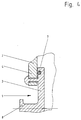
- FIG. 4 shows an exemplary embodiment similar to the exemplary embodiment from FIG. 3, the cover being reshaped by a method similar to riveting in the case of metallic materials and thereby held in the edge region of the intake pipe.
- a plastic suction pipe 2 which has a production-related opening 1, which is closed from the inside by a cover 3.
- the cover 3 completely covers the opening 1 of the plastic suction pipe 2.
- Both the opening 1 and the lid 3 each have a non-circular cross-section, so that the relatively larger lid can be passed through the relatively smaller opening 1 by corresponding rotation and is then positioned such that it from the inside of the plastic suction pipe 2 Closes opening 1 gastight.
- the cover 3 consists of a thermoplastic and has projections 5 in the direction of the edge region 4 of the opening 1, which protrusions at least partially melt by vibration welding and can therefore be brought into engagement with the intake pipe 2. The cover fastened by vibration welding is held permanently and gas-tight on the plastic suction pipe 2.
- the cover 3 is formed in the edge area 4 of the plastic suction pipe 2 by a barb-shaped snap-in device 6.
- the cover 3 has a circumferential groove which is open in the direction of the opening 1 and into which a seal 7, in this example an O-ring, is inserted.
- the cover In its central area, the cover has a holding device 8 for better handling during assembly.
- the cover 3 and the suction pipe 2 are made of plastic.
- FIG. 4 shows an exemplary embodiment which is similar to the exemplary embodiment from FIG. 3.
- pins formed in one piece with the lid are used, which are guided after the insertion of the lid 3 into the plastic suction pipe 2 through recesses in the edge region 4 and are then reshaped in such a way that the lid 3 opens 1 when subjected to negative pressure and Seals excess pressure reliably.
- the plastic suction pipe according to the invention has good performance properties over a long period of use.
Landscapes
- Engineering & Computer Science (AREA)
- Chemical & Material Sciences (AREA)
- Combustion & Propulsion (AREA)
- Mechanical Engineering (AREA)
- General Engineering & Computer Science (AREA)
- Manufacturing & Machinery (AREA)
- Characterised By The Charging Evacuation (AREA)
- Lining Or Joining Of Plastics Or The Like (AREA)
Description
- Die Erfindung betrifft ein Kunststoffsaugrohr einer Verbrennungskraftmaschine und ein Verfahren zum Verschließen einer Öffnung durch einen Deckel angepaßten Profils.
- Ein Kunststoffsaugrohr für Verbrennungskraftmaschinen ist aus der DE 35 36 522 A1 bekannt. In eine an einem Wandabschnitt des Saugrohrs vorgesehene Öffnung ist ein Verschlußorgan eingesetzt, das ab einem definierten Überdruck im Saugrohr öffnet. Das Verschlußorgan ist als Druck-Sicherheitsventil ausgeführt. Beschädigungen des Saugrohrs bei Flammrückschlägen bzw. Fehlzündungen sollen dadurch vermieden werden. Das Kunststoffsaugrohr wird nach der Schmelzkerntechnik hergestellt, wobei im Saugrohr Öffnungen erforderlich sind, über die der Schmelzkern während des Umspritzens mit Kunststoff in der Form fixert ist. Die Öffnungen werden genutzt, um das Verschlußorgan aufzunehmen. Das Verschlußorgan ist als Verschlußstopfen ausgebildet, in die Öffnung eingeclipst und verliergesichert in dieser gehalten. Der Verschlußstopfen ist kreisringförmig ausgebildet und weist auf der dem Kunststoffsaugrohr zugewandten Seite in radialer Richtung einfederbare Haltezungen auf, die mit Hinterschneidungen in das Ansaugrohr einschnappbar sind. Zur Abdichtung gegenüber dem Ansaugrohr weist der Verschlußstopfen eine umfangsseitig umlaufende, nutförmige Ausnehmung auf, die in Richtung des Ansaugrohrs geöffnet ist, wobei innerhalb der Ausnehmung zur Abdichtung ein O-Ring unter elastischer Vorspannung dichtend angeordnet ist.
- Zur Herstellung der Kunststoffsaugrohre werden durch eine Haltevorrichtung gehaltene Kerne umspritzt, wobei nach dem Entfernen der Kerne fertigungsbedingte Öffnungen in den Kunststoffsaugrohren zurückbleiben, die zur Funktion verschlossen werden müssen. Es ist bekannt, daß diese Öffnungen kreisförmig ausgebildet sind und durch entsprechend ausgebildete Deckel aus thermoplastischem Kunststoff durch Reibschweißen oder Ultraschallschweißen verschlossen werden. Dabei ist allerdings zu beachten, daß die Gebrauchseigenschaften derartiger Kunststoffsaugrohre wenig befriedigend sind. Die vorbekannten Kunststoffsaugrohre sind besonders empfindlich gegen Überdruck, der beispielsweise dann im Saugrohr anliegt, wenn der Verbrennungsdruck durch Unregelmäßigkeiten im Verbrennundablauf der Verbrennungskraftmaschine in das Saugrohr zurückschlägt. In diesem Falle werden die Deckel in der Öffnung oftmals nicht mehr gehalten und die Gebrauchseigenschaften der Verbrennungskraftmaschine beeinträchtigt.
- Der Erfindung liegt die Aufgabe zugrunde, ein Kunstoffsaugrohr und ein Verfahren zum Verschließen der Öffnungen zu zeigen, bei dem die vorgenannten Nachteile nicht mehr auftreten. Das Saugrohr soll einem Überdruck standhalten, der auftreten kann, wenn der Verbrennungsdruck in die Sauganlage zurückschlägt.
- Diese Aufgabe wird erfindungsgemäß mit einem Verfahren und durch ein Kunststoffsaugrohr gemäß der Ansprüche 1 und 2 gelöst. Auf vorteilhafte Ausgestaltungen nehmen die Unteransprüche Bezug.
- Im Hinblick auf eine gute Haltbarkeit des Kunststoffsaugrohrs auch bei Einleitung von Überdruck, der beispielsweise dann anliegt, wenn sich der Verbrennungsdruck durch eine fehlerhaft eingestellte Verbrennungskraftmaschine bis in die Sauganlage ausbreitet, ist es vorgesehen, daß nicht kreisrunde Öffnungen im Kunststoffsaugrohr einer Verbrennungskraftmaschine mit Deckeln angepaßter Gestalt verschlossen werden und zwar derart, daß der Deckel, der eine Querschnittsfläche aufweist, die größer ist als die Querschnittsfläche der Öffnung, relativ verdreht von außen durch die Öffnung eingeführt und anschließend in dem Kunststoffsaugrohr soweit zurückgedreht wird, daß er die Öffnung und einen die Öffnung umschließenden Randbereich des Saugrohr von innen durch Formschluß vollständig überdeckt.
- Das Kunststoffsaugrohr zur Verwendung bei einem derartigen Verfahren weist Öffnungen auf, die durch Deckel angepaßter Gestalt verschließbar sind, wobei die Öffnungen einen nicht kreisringförmigen Querschnitt aufweisen, wobei die Deckel relativ verdrehbar von außen durch die Öffnungen einführbar und anschließend im Kunststoffsaugrohr soweit zurückdrehbar sind, daß die Deckel die Öffnungen und einen die Öffnungen umschließenden Randbereich des Kunststoffsaugrohrs von innen formschlüssig und vollständig überdecken. Hierbei ist von Vorteil, daß das Kunststoffsaugrohr eine gute Haltbarkeit gegen eventuell auftretenden Überdruck aufweist. Der Deckel wird von innen am Randbereich des Saugrohrs, der die Öffnung umschließt, befestigt.
- Gemäß einer vorteilhaften Ausgestaltung können die Öffnung und der Deckel jeweils oval ausgeführt sein, wobei das Verhältnis von Hauptachse zu Nebenachse bevorzugt 1,1:1 bis 3:1 beträgt. Die Montage des Deckels gestaltet sich dabei besonders einfach. Verkantungen bei der Montage des Deckels in der Öffnung kann durch diese Ausgestaltung vorgebeugt werden. In Abhängigkeit von den jeweiligen Gegebenheiten des Anwendungsfalls insbeson dere dem Durchtrittsquerschnitt innerhalb des Saugrohrs sind die Abmessungen von Deckel und Öffnung anzupassen.
- Eine in fertigungstechnischer und wirtschaftlicher Hinsicht besonders günstige Ausgestaltung kann durch eine Öffnung und einen Deckel gegeben sein, die im wesentlichen eckig ausgebildet sind. Die Form von Öffnung und Deckel kann beispielsweise quaratisch sein. Davon abweichende, mehreckige Ausgestaltungen sind ebenfalls denkbar. Zum Verschließen der Öffnung durch den Deckel von innen kann der Deckel zunächst aus der Ebene der Öffnung um 90° in eine Ebene senkrecht dazu gedreht und anschließend um 45° gekippt werden, so daß er anschließend diagonal durch die Öffnung geführt werden kann. Innerhalb des Saugrohrs wird der Deckel dann wieder in seine Ausgangsposition zurückbewegt bis er die Öffnung vollständig überdeckt und anschließend an dem Randbereich der Öffnung festgelegt.
- Zum Befestigen des Deckels kann dieser auf der der Öffnung zugewandten Seite zumindest teilweise mit einem Kleber beschichtet sein, um von innen im Randbereich um die Öffnung angeklebt zu werden. Dem vergleichsweise geringen Unterdruck innerhalb des Saugrohrs hält eine derartige Verbindung problemlos stand. Auftretender Überdruck innerhalb der Sauganlage vermag den Deckel durch den im Vergleich zur Öffnung größeren Querschnitt nicht aus dem Kunststoffsaugrohr zu sprengen. Die Funktionstüchtigkeit der Verbrennungskraftmaschine bleibt erhalten und eine Beschädigung des Kunststoffsaugrohrs erfolgt nicht. Bedarfsweise können die Öffnung und/oder der Deckel auf den einander zugewandten Seiten mit einer Flüssigdichtung versehen sein. Eine zuverlässige Abdichtung des Saugrohrs zur Umgebung ist dadurch gewährleistet.
- Nach einer anderen Ausgestaltung kann es vorgesehen sein, daß der Deckel aus einem thermoplastischen Kunststoff besteht und auf der der Öffnung zugewandten Seite einstückig angeformte Vorsprünge aufweist, die durch Vibrationsschweißen mit dem Randbereich der Öffnung in Eingriff bringbar sind. Beim Vibrationsschweißen sind die Kontaktflächen der zu verschweißenden Teile, in diesem Fall der Randbereich, der die Öffnung begrenzt und der Deckel, so zu gestalten, daß die sich bildende Schmelze allseitig Freiraum zur Bildung einer Schweißbraue hat. Die Schmelze erstreckt sich beim Vibrationsschweißen dann umfangsseitig entlang des Randbereichs, befestigt den Deckel und dichtet die Öffnung des Kunststoffsaugrohrs ab.
- Gemäß einer anderen vorteilhaften Ausgestaltung ist es vorgesehen, daß der Deckel mit einer Einschnappvorrichtung versehen ist und daß die Einschnappvorrichtung von innen in die zu verschließende Öffnung einschnappbar ist. Die Einschnappvorrichtung kann beispielsweise durch mehrere umfangsseitig am Deckel ausgebildete, widerhakenartige Krallen gebildet sein, die den Randbereich der Öffnung unter axialer Vorspannung umschließen. Diese Ausgestaltung ist in fertigungstechnischer Hinsicht einfach, da der ohnehin vorhandene Randbereich der fertigungsbedingen Öffnung als Widerlager genutzt werden kann. Ein Einschnappen des Deckels in eine separat erzeugte, dafür vorgesehene Öffnung ist aber ebenfalls möglich.
- Zur verbesserten Abdichtung, insbesondere bei Verwendung eines Deckels mit Einschnappvorrichtung, kann diese zumindest eine in Richtung der Öffnung offene und diese umfangsseitig umschließende Nut aufweisen, in die eine Dichtung einlegbar ist. Als Dichtung kann beispielsweise zumindest ein O-Ring zur Anwendung gelangen, der gute Gebrauchseigenschaften auch noch nach einer langen Gebrauchsdauer und wechselnden Belastungen aufweisen. Neben einer O-Ring Dichtungen, die in die Nut eingelegt werden kann, kann beispielsweise auch eine Flüssigdichtungen wie Silikon zur Anwendung gelangen, die zwischen dem Deckel und dem Randbereich um die Öffnung angeordnet ist.
- Um eine Vereinfachung der Montage des Deckels im Kunststoffsaugrohr zu erreichen, kann der Deckel eine einstückig angeformte Haltevorrichtung aufweisen, beispielsweise einen zentrisch auf der dem Saugrohr abgewandten Seite am Deckel angeordneten Halteknauf. Eine maschinelle Endmontage wird dadurch begünstigt.
- Im folgenden werden die als Anlage beigefügten Zeichnungen erläutert. Diese zeigen jeweils einen Ausschnitt aus einem erfindungsgemäßen Kunststoffsaugrohr für eine Verbrennungskraftmaschine in geschnittener und teilweise schematischer Darstellung.
- In den Figuren 1 und 2 ist ein Ausführungsbeispiel eines erfindungsgemäßen Kunststoffsaugrohrs gezeigt, wobei die Schnitte von Figur 1 und Figur 2 um 90° versetzt zueinander angeordnet sind.
In Figur 3 ist ein weiteres Ausführungsbeispiel gezeigt, wobei der Deckel im Randbereich, der die Öffnung umschließt, in das Ansaugrohr eingeschnappt ist.
In Figur 4 ist eine Ausführungsbeispiel ähnlich dem Ausführungsbeispiel aus Figur 3 gezeigt, wobei der Deckel durch ein Verfahren, ähnlich dem Nieten bei metallischen Werkstoffen umgeformt und dadurch im Randbereich des Ansaugrohrs gehalten wird. - Im Ausführungsbeispiel gemäß der Figuren 1 und 2 ist ein Kunststoffsaugrohr 2 gezeigt, das eine fertigungsbedingte Öffnung 1 aufweist, die von innen durch einen Deckel 3 verschlossen ist. Wie aus den Figuren 1 und 2 zu ersehen ist, überdeckt der Deckel 3 die Öffnung 1 des Kunststoffsaugrohrs 2 vollständig. Sowohl die Öffnung 1 als auch der Deckel 3 weisen jeweils einen nicht kreisförmigen Querschnitt auf, so daß der relativ größere Deckel durch entsprechendes Verdrehen durch die relativ kleinere Öffnung 1 geführt werden kann und anschließend derart positioniert wird, daß er von der Innenseite des Kunststoffsaugrohrs 2 die Öffnung 1 gasdicht verschließt. Der Deckel 3 besteht in diesem Ausführungsbeispiel aus einem thermoplastischen Kunststoff und weist in Richtung des Randbereichs 4 der Öffnung 1 Vorsprünge 5 auf, die durch Vibrationsschweißen zumindest teilweise abschmelzen und dadurch mit dem Ansaugrohr 2 in Eingriff bringbar sind. Der durch Vibrationsschweißen befestigte Deckel wird dauerhaft und gasdicht am Kunststoffsaugrohr 2 gehalten.
- In Figur 3 ist der Deckel 3 im Randbereich 4 des Kunststoffsaugrohrs 2 durch eine widerhakenförmige Einschnappvorrichtung 6 gebildet. Zur zuverlässigen Abdichtung des nicht kreisförmigen Deckels 3 in der nicht kreisförmigen Öffnung 1 weist der Deckel 3 eine in Richtung der Öffnung 1 offene umfangsseitig umlaufende Nut auf, in die eine Dichtung 7, in diesem Beispiel ein O-Ring, eingelegt ist. In seinem zentralen Bereich weist der Deckel eine Haltevorrichtung 8 zur besseren Handhabung während der Montage auf. Auch in diesem Beispiel bestehen der Deckel 3 und das Saugrohr 2 aus Kunststoff.
- In Figur 4 ist ein Ausführungsbeispiel gezeigt, das dem Ausführungsbeispiel aus Figur 3 ähnlich ist. Anstelle der Einschnappvorrichtung 6 gelangen in diesem Beispiel einstückig mit dem Deckel ausgebildete Stifte zur Anwendung, die nach dem Einführen des Deckels 3 in das Kunststoffsaugrohr 2 durch Ausnehmungen im Randbereich 4 geführt werden und anschließend derart umgeformt werden, daß der Deckel 3 die Öffnung 1 bei Beaufschlagung mit Unterdruck und Überdruck zuverlässig abdichtet.
- Das erfindungsgemäße Kunststoffsaugrohr weist gute Gebrauchseigenschaften während einer langen Gebrauchsdauer auf.
Claims (10)
- Verfahren zum Verschließen einer Öffnung (1) eines Kunststoffsaugrohres (2) einer Verbrennungskraftmaschine, bei dem die Öffnung (1) durch einen Deckel (3) angepaßter Gestalt verschlossen wird, dadurch gekennzeichnet, daß die Öffnung (1) nicht kreisförmig ausgebildet ist, daß der Deckel (3) eine Querschnittsfläche aufweist, die größer ist als die Querschnittsfläche der Öffnung (1) und relativ verdreht von außen durch die Öffnung (1) eingeführt und anschließend in dem Kunststoffsaugrohr (2) soweit zurückgedreht wird, daß er die Öffnung (1) und einen die Öffnung (1) umschließenden Randbereich (4) des Kunststoffsaugrohrs (2) von innen durch Formschluß vollständig überdeckt.
- Kunststoffsaugrohr mit Deckel zur Verwendung bei einem Verfahren nach Anspruch 1, wobei das Kunststoffsaugrohr (2) eine Öffnung (1) aufweist, die durch den Deckel (3) angepaßter Gestalt verschließbar ist, dadurch gekennzeichnet, daß die Öffnung (1) einen nicht kreisförmigen Querschnitt aufweist, daß der Deckel (3) eine Querschnittsfläche aufweist, die größer ist als die Querschnittsfläche der Öffnung (1) und relativ verdrehbar von außen durch die Öffnung (1) einführbar und anschließend im Kunststoffsaugrohr (2) soweit zurückverdrehbar ist, daß der Deckel (3) die Öffnung (1) und einen die Öffnung (1) umschließenden Randbereich (4) des Kunststoffsaugrohrs (2) von innen formschlüssig und vollständig überdeckt.
- Kunststoffsaugrohr nach Anspruch 2, dadurch gekennzeichnet, daß die Öffnung (1) und der Deckel (3) jeweils oval ausgeführt sind und das Verhältnis von Hauptachse zu Nebenachse 1,1:1 bis 3:1 beträgt.
- Kunststoffsaugrohr nach Anspruch 2, dadurch gekennzeichnet, daß die Öffnung (1) und der Deckel (3) im wesentlichen eckig ausgebildet sind.
- Kunststoffsaugrohr nach Anspruch 4, dadurch gekennzeichnet, daß die Öffnung (1) und der Deckel (3) quadratisch ausgebildet sind.
- Kunststoffsaugrohr nach Anspruch 2 bis 5, dadurch gekennzeichnet, daß der Deckel (3) auf der der Öffnung (1) zugewandten Seite zumindest teilweise mit einem Kleber beschichtet ist.
- Kunststoffsaugrohr nach Anspruch 2 bis 5, dadurch gekennzeichnet, daß der Deckel (3) aus einem thermoplastischen Kunststoff besteht und auf der der Öffnung (1) zugewandten Seite einstückig angeformte Vorsprünge (5) aufweist, die durch Vibrationsschweißen mit dem Kunststoffsaugrohr (2) in Eingriff bringbar sind.
- Kunststoffsaugrohr nach Anspruch 2 bis 5, dadurch gekennzeichnet, daß der Deckel (3) mit einer Einschnappvorrichtung (6) versehen ist und daß die Einschnappvorrichtung (6) in die zu verschließende Öffnung (1) einschnappbar ist.
- Kunststoffsaugrohr nach Anspruch 2 bis 8, dadurch gekennzeichnet, daß der Deckel (3) eine in Richtung der Öffnung (1) offene und diese umfangsseitig umschließende Nut aufweist, in die eine Dichtung (7) einlegbar ist.
- Kunststoffsaugrohr nach Anspruch 2 bis 9, dadurch gekennzeichnet, daß der Deckel (3) eine einstückig angeformte Haltevorrichtung (8) aufweist.
Applications Claiming Priority (2)
| Application Number | Priority Date | Filing Date | Title |
|---|---|---|---|
| DE4222020A DE4222020C1 (de) | 1992-07-04 | 1992-07-04 | Kunststoffsaugrohr |
| DE4222020 | 1992-07-04 |
Publications (2)
| Publication Number | Publication Date |
|---|---|
| EP0577882A1 EP0577882A1 (de) | 1994-01-12 |
| EP0577882B1 true EP0577882B1 (de) | 1995-11-02 |
Family
ID=6462500
Family Applications (1)
| Application Number | Title | Priority Date | Filing Date |
|---|---|---|---|
| EP92121598A Expired - Lifetime EP0577882B1 (de) | 1992-07-04 | 1992-12-18 | Kunststoffsaugrohr |
Country Status (3)
| Country | Link |
|---|---|
| US (1) | US5435279A (de) |
| EP (1) | EP0577882B1 (de) |
| DE (2) | DE4222020C1 (de) |
Families Citing this family (5)
| Publication number | Priority date | Publication date | Assignee | Title |
|---|---|---|---|---|
| US5601059A (en) * | 1995-08-09 | 1997-02-11 | Brunswick Corporation | Fuel distribution insert for internal combustion engine |
| US5595151A (en) * | 1995-12-11 | 1997-01-21 | Siemens Electric Limited | Releasable connection for molded parts |
| DE19826261A1 (de) * | 1998-06-15 | 1999-12-16 | Mann & Hummel Filter | Ansaugsystem |
| DE10082489C5 (de) * | 2000-08-11 | 2017-10-26 | Schaeffler Technologies AG & Co. KG | Ausrücksystem |
| US6418888B1 (en) * | 2000-10-24 | 2002-07-16 | Siemens Vdo Automotive, Inc. | Ultra sonic or heat staked fastening for air intake manifold active system |
Family Cites Families (5)
| Publication number | Priority date | Publication date | Assignee | Title |
|---|---|---|---|---|
| DE909785C (de) * | 1951-11-17 | 1954-04-26 | Hch Bertrams A G | Einrichtung an Rohrkruemmern oder Rohren, insbesondere verbleiten Ofenrohrknien |
| US3044920A (en) * | 1957-01-15 | 1962-07-17 | Dunlop Rubber Co | Repair of thermoplastic materials |
| GB2067253A (en) * | 1980-01-11 | 1981-07-22 | United Carr Ltd | Aperture plug |
| CA1167786A (en) * | 1981-01-22 | 1984-05-22 | Guenter Jahn | Clean out device |
| DE3536522A1 (de) * | 1985-10-12 | 1987-04-16 | Audi Ag | Saugrohr fuer eine brennkraftmaschine |
-
1992
- 1992-07-04 DE DE4222020A patent/DE4222020C1/de not_active Expired - Lifetime
- 1992-12-18 EP EP92121598A patent/EP0577882B1/de not_active Expired - Lifetime
- 1992-12-18 DE DE59204205T patent/DE59204205D1/de not_active Expired - Lifetime
-
1993
- 1993-06-25 US US08/083,743 patent/US5435279A/en not_active Expired - Fee Related
Also Published As
| Publication number | Publication date |
|---|---|
| US5435279A (en) | 1995-07-25 |
| EP0577882A1 (de) | 1994-01-12 |
| DE4222020C1 (de) | 1994-01-20 |
| DE59204205D1 (de) | 1995-12-07 |
Similar Documents
| Publication | Publication Date | Title |
|---|---|---|
| EP2054648B1 (de) | Dichtungs- oder faltenbalg | |
| DE112007000633B4 (de) | Lufteinlassgeräusch-Minderungsvorrichtung, Brennkraftmaschine, die mit derselben ausgerüstet ist und Struktur zum Einpassen derselben an der Brennkraftmaschine | |
| DE4022558A1 (de) | Dichtungsvorrichtungen fuer durchflussoeffnungen | |
| DE4406737A1 (de) | Maschinendeckel, Dichtung hierfür und Anordnung aus Maschinendeckel und Dichtung | |
| EP1129286B1 (de) | Kraftstoffeinspritzventil für brennkraftmaschinen | |
| DE102007013937A1 (de) | Drosselklappengehäuse sowie Verfahren zur Herstellung des Drosselklappengehäuses | |
| EP1743110A1 (de) | Ventilanordnung in einer kurbelgehäuseentlüftung | |
| EP0618387A1 (de) | Dichtung | |
| EP0433659A2 (de) | Thermostatventil | |
| DE102013101992A1 (de) | Halteplatte und Verfahren zur Herstellung einer Halteplatte | |
| DE10334898B4 (de) | Halteelement zur Fixierung wenigstens eines Lagers | |
| WO2004000632A1 (de) | Verschlussdeckel | |
| EP0577882A1 (de) | Kunststoffsaugrohr | |
| DE102012220695A1 (de) | Drehverschlussanordnung zum Verschließen einer Öffnung in einem Gehäuseteil eines Verbrennungsmotors, und Verfahren zum Verschließen bzw. Öffnen einer solchen Öffnung | |
| EP0460489A1 (de) | Verfahren zur Befestigung eines aus Kunststoff bestehenden Verschlussdeckels in einer Trägeröffnung | |
| DE1576540A1 (de) | Luftfilter | |
| DE10301235A1 (de) | Verfahren zur Herstellung einer Gummiformdichtung | |
| EP0307971B1 (de) | Kupplungsmuffe zum Verbinden von zwei Rohrleitungsenden | |
| DE9403868U1 (de) | Filtereinsatz, insbesondere für Öl- oder Kraftstoffilter | |
| EP0571663A1 (de) | Ansaugrohr für eine Verbrennungskraftmaschine | |
| WO2017076558A1 (de) | Behälter mit versteifungseinrichtung | |
| DE19516927A1 (de) | Drosselklappendichtung | |
| EP1520129B1 (de) | Schieberventil | |
| DE19748974C1 (de) | Befestigungselement, insbesondere zur spielfreien Montage eines Bauelements zwischen zwei Gehäusehälften | |
| DE19911696A1 (de) | Dichtungsanordnung zum statischen Abdichten einer fluidführenden Verbindung |
Legal Events
| Date | Code | Title | Description |
|---|---|---|---|
| PUAI | Public reference made under article 153(3) epc to a published international application that has entered the european phase |
Free format text: ORIGINAL CODE: 0009012 |
|
| 17P | Request for examination filed |
Effective date: 19931013 |
|
| AK | Designated contracting states |
Kind code of ref document: A1 Designated state(s): AT DE FR GB IT SE |
|
| RAP3 | Party data changed (applicant data changed or rights of an application transferred) |
Owner name: FIRMA CARL FREUDENBERG |
|
| 17Q | First examination report despatched |
Effective date: 19941004 |
|
| RBV | Designated contracting states (corrected) |
Designated state(s): DE FR GB |
|
| GRAA | (expected) grant |
Free format text: ORIGINAL CODE: 0009210 |
|
| AK | Designated contracting states |
Kind code of ref document: B1 Designated state(s): DE FR GB |
|
| REF | Corresponds to: |
Ref document number: 59204205 Country of ref document: DE Date of ref document: 19951207 |
|
| GBT | Gb: translation of ep patent filed (gb section 77(6)(a)/1977) |
Effective date: 19951129 |
|
| ET | Fr: translation filed | ||
| PLBE | No opposition filed within time limit |
Free format text: ORIGINAL CODE: 0009261 |
|
| STAA | Information on the status of an ep patent application or granted ep patent |
Free format text: STATUS: NO OPPOSITION FILED WITHIN TIME LIMIT |
|
| 26N | No opposition filed | ||
| PGFP | Annual fee paid to national office [announced via postgrant information from national office to epo] |
Ref country code: GB Payment date: 19961129 Year of fee payment: 5 |
|
| PGFP | Annual fee paid to national office [announced via postgrant information from national office to epo] |
Ref country code: FR Payment date: 19961203 Year of fee payment: 5 |
|
| PGFP | Annual fee paid to national office [announced via postgrant information from national office to epo] |
Ref country code: DE Payment date: 19961205 Year of fee payment: 5 |
|
| PG25 | Lapsed in a contracting state [announced via postgrant information from national office to epo] |
Ref country code: GB Free format text: LAPSE BECAUSE OF NON-PAYMENT OF DUE FEES Effective date: 19971218 |
|
| PG25 | Lapsed in a contracting state [announced via postgrant information from national office to epo] |
Ref country code: FR Free format text: THE PATENT HAS BEEN ANNULLED BY A DECISION OF A NATIONAL AUTHORITY Effective date: 19971231 |
|
| PG25 | Lapsed in a contracting state [announced via postgrant information from national office to epo] |
Ref country code: DE Free format text: LAPSE BECAUSE OF THE APPLICANT RENOUNCES Effective date: 19980121 |
|
| GBPC | Gb: european patent ceased through non-payment of renewal fee |
Effective date: 19971218 |
|
| REG | Reference to a national code |
Ref country code: FR Ref legal event code: ST |