EP0576156B1 - Système de transmission mécanique semi-automatique améliorisée - Google Patents
Système de transmission mécanique semi-automatique améliorisée Download PDFInfo
- Publication number
- EP0576156B1 EP0576156B1 EP93304171A EP93304171A EP0576156B1 EP 0576156 B1 EP0576156 B1 EP 0576156B1 EP 93304171 A EP93304171 A EP 93304171A EP 93304171 A EP93304171 A EP 93304171A EP 0576156 B1 EP0576156 B1 EP 0576156B1
- Authority
- EP
- European Patent Office
- Prior art keywords
- transmission
- shift
- ratio
- engine
- neutral
- Prior art date
- Legal status (The legal status is an assumption and is not a legal conclusion. Google has not performed a legal analysis and makes no representation as to the accuracy of the status listed.)
- Expired - Lifetime
Links
- 230000009347 mechanical transmission Effects 0.000 title claims description 18
- 230000005540 biological transmission Effects 0.000 claims description 75
- 230000007935 neutral effect Effects 0.000 claims description 28
- 239000000446 fuel Substances 0.000 claims description 14
- 238000000034 method Methods 0.000 claims description 10
- 230000008859 change Effects 0.000 claims description 8
- 238000012790 confirmation Methods 0.000 claims 1
- 230000001360 synchronised effect Effects 0.000 description 10
- 150000001875 compounds Chemical class 0.000 description 6
- 230000000712 assembly Effects 0.000 description 4
- 238000000429 assembly Methods 0.000 description 4
- 230000000977 initiatory effect Effects 0.000 description 4
- 230000009467 reduction Effects 0.000 description 4
- 239000012530 fluid Substances 0.000 description 3
- 230000008569 process Effects 0.000 description 3
- 230000008676 import Effects 0.000 description 2
- 241000219098 Parthenocissus Species 0.000 description 1
- 230000003247 decreasing effect Effects 0.000 description 1
- 230000000881 depressing effect Effects 0.000 description 1
Images


Classifications
-
- B—PERFORMING OPERATIONS; TRANSPORTING
- B60—VEHICLES IN GENERAL
- B60W—CONJOINT CONTROL OF VEHICLE SUB-UNITS OF DIFFERENT TYPE OR DIFFERENT FUNCTION; CONTROL SYSTEMS SPECIALLY ADAPTED FOR HYBRID VEHICLES; ROAD VEHICLE DRIVE CONTROL SYSTEMS FOR PURPOSES NOT RELATED TO THE CONTROL OF A PARTICULAR SUB-UNIT
- B60W10/00—Conjoint control of vehicle sub-units of different type or different function
- B60W10/04—Conjoint control of vehicle sub-units of different type or different function including control of propulsion units
- B60W10/06—Conjoint control of vehicle sub-units of different type or different function including control of propulsion units including control of combustion engines
-
- B—PERFORMING OPERATIONS; TRANSPORTING
- B60—VEHICLES IN GENERAL
- B60W—CONJOINT CONTROL OF VEHICLE SUB-UNITS OF DIFFERENT TYPE OR DIFFERENT FUNCTION; CONTROL SYSTEMS SPECIALLY ADAPTED FOR HYBRID VEHICLES; ROAD VEHICLE DRIVE CONTROL SYSTEMS FOR PURPOSES NOT RELATED TO THE CONTROL OF A PARTICULAR SUB-UNIT
- B60W10/00—Conjoint control of vehicle sub-units of different type or different function
- B60W10/04—Conjoint control of vehicle sub-units of different type or different function including control of propulsion units
-
- B—PERFORMING OPERATIONS; TRANSPORTING
- B60—VEHICLES IN GENERAL
- B60W—CONJOINT CONTROL OF VEHICLE SUB-UNITS OF DIFFERENT TYPE OR DIFFERENT FUNCTION; CONTROL SYSTEMS SPECIALLY ADAPTED FOR HYBRID VEHICLES; ROAD VEHICLE DRIVE CONTROL SYSTEMS FOR PURPOSES NOT RELATED TO THE CONTROL OF A PARTICULAR SUB-UNIT
- B60W10/00—Conjoint control of vehicle sub-units of different type or different function
- B60W10/10—Conjoint control of vehicle sub-units of different type or different function including control of change-speed gearings
- B60W10/11—Stepped gearings
- B60W10/111—Stepped gearings with separate change-speed gear trains arranged in series
-
- B—PERFORMING OPERATIONS; TRANSPORTING
- B60—VEHICLES IN GENERAL
- B60W—CONJOINT CONTROL OF VEHICLE SUB-UNITS OF DIFFERENT TYPE OR DIFFERENT FUNCTION; CONTROL SYSTEMS SPECIALLY ADAPTED FOR HYBRID VEHICLES; ROAD VEHICLE DRIVE CONTROL SYSTEMS FOR PURPOSES NOT RELATED TO THE CONTROL OF A PARTICULAR SUB-UNIT
- B60W30/00—Purposes of road vehicle drive control systems not related to the control of a particular sub-unit, e.g. of systems using conjoint control of vehicle sub-units
- B60W30/18—Propelling the vehicle
- B60W30/1819—Propulsion control with control means using analogue circuits, relays or mechanical links
-
- B—PERFORMING OPERATIONS; TRANSPORTING
- B60—VEHICLES IN GENERAL
- B60W—CONJOINT CONTROL OF VEHICLE SUB-UNITS OF DIFFERENT TYPE OR DIFFERENT FUNCTION; CONTROL SYSTEMS SPECIALLY ADAPTED FOR HYBRID VEHICLES; ROAD VEHICLE DRIVE CONTROL SYSTEMS FOR PURPOSES NOT RELATED TO THE CONTROL OF A PARTICULAR SUB-UNIT
- B60W30/00—Purposes of road vehicle drive control systems not related to the control of a particular sub-unit, e.g. of systems using conjoint control of vehicle sub-units
- B60W30/18—Propelling the vehicle
- B60W30/19—Improvement of gear change, e.g. by synchronisation or smoothing gear shift
-
- F—MECHANICAL ENGINEERING; LIGHTING; HEATING; WEAPONS; BLASTING
- F16—ENGINEERING ELEMENTS AND UNITS; GENERAL MEASURES FOR PRODUCING AND MAINTAINING EFFECTIVE FUNCTIONING OF MACHINES OR INSTALLATIONS; THERMAL INSULATION IN GENERAL
- F16H—GEARING
- F16H61/00—Control functions within control units of change-speed- or reversing-gearings for conveying rotary motion ; Control of exclusively fluid gearing, friction gearing, gearings with endless flexible members or other particular types of gearing
- F16H61/02—Control functions within control units of change-speed- or reversing-gearings for conveying rotary motion ; Control of exclusively fluid gearing, friction gearing, gearings with endless flexible members or other particular types of gearing characterised by the signals used
- F16H61/0202—Control functions within control units of change-speed- or reversing-gearings for conveying rotary motion ; Control of exclusively fluid gearing, friction gearing, gearings with endless flexible members or other particular types of gearing characterised by the signals used the signals being electric
- F16H61/0248—Control units where shifting is directly initiated by the driver, e.g. semi-automatic transmissions
-
- F—MECHANICAL ENGINEERING; LIGHTING; HEATING; WEAPONS; BLASTING
- F16—ENGINEERING ELEMENTS AND UNITS; GENERAL MEASURES FOR PRODUCING AND MAINTAINING EFFECTIVE FUNCTIONING OF MACHINES OR INSTALLATIONS; THERMAL INSULATION IN GENERAL
- F16H—GEARING
- F16H63/00—Control outputs from the control unit to change-speed- or reversing-gearings for conveying rotary motion or to other devices than the final output mechanism
- F16H63/40—Control outputs from the control unit to change-speed- or reversing-gearings for conveying rotary motion or to other devices than the final output mechanism comprising signals other than signals for actuating the final output mechanisms
- F16H63/50—Signals to an engine or motor
- F16H63/502—Signals to an engine or motor for smoothing gear shifts
Definitions
- This invention relates to vehicular semi-automatic mechanical transmission systems and, in particular, to semi-automatic mechanical transmission systems of the type providing partially automatic implementation of a manually or automatically selected shifting of mechanical transmission gear ratios.
- Transmission systems of this type are disclosed in U.S. Patent Nos. 5,053,961 and 5,053,962, both assigned to the assignee of this application. More particularly, the present invention relates to a semi-automated transmission system of the type described which is provided with an engine fuel controller controlled by the system control unit for causing synchronous conditions after manual fuel or clutch manipulation to initiate a shift sequence by causing a torque break.
- Fully automatic transmission systems both for heavy-duty vehicles such as heavy-duty trucks, and for automobiles, that sense throttle openings or positions, vehicle speeds, engine speeds, and the like, and automatically shift the vehicle transmission in accordance therewith, are well known in the prior art.
- Such fully automatic change gear transmission systems include automated transmissions wherein pressurized fluid is utilized to frictionally engage one or more members to other members or to a ground to achieve a selected gear ratio as well as automated mechanical transmissions utilizing electronic and/or pneumatic logic and actuators to engage and disengage mechanical (i.e. positive) clutches to achieve a desired gear ratio. Examples of such transmissions may be seen by reference to U.S. Pat. Nos. 3,961,546; 4,081,065 and 4,361,060.
- Such fully automatic change gear transmissions can be unacceptably expensive, particularly for the largest heavy-duty vehicles which are not typically sold in high volumes. Additionally, those automatic change gear transmissions utilizing pressurized fluid and/or torque converters tend to be relatively inefficient in terms of power dissipated between the input and output shafts thereof.
- Semi-automatic transmission systems utilizing electronic control units which sense throttle position, engine, input shaft, output shaft and/or vehicle speed, and utilize automatically controlled fuel throttle devices, gear shifting devices and/or master clutch operating devices to substantially fully automatically implement operator manually selected transmission ratio changes are known in the prior. Examples of such semi-automatic transmission systems may be seen by reference to U.S. Pat. Nos. 4,425,620; 4,631,679 and 4,648,290.
- a semi-automatic shift implementation system/method for a mechanical transmission system for use in vehicles having a manually only controlled engine throttle means, and a manually only controlled master clutch is disclosed in above-mentioned U.S. Patent Nos. 5,053,961 and 5,053,962.
- This system includes a control/display panel or console for operator selection of upshifts, downshifts or shifts into neutral, an electronic control unit (ECU) for receiving input signals indicative of transmission input and output shaft speeds and of manually selected shifts and for processing same in accordance with predetermined logic rules to issue command output signals and a transmission actuator for shifting the transmission in accordance with the command output signals.
- ECU electronice control unit
- the control/display device will allow the operator to select/preselect a shift into a higher ratio, a lower ratio or into neutral and preferably will display the selected but not yet implemented shift as well as the current status of the transmission. Preferable the control will also allow selection of operation in an automatic preselection mode of operation.
- Figure 1 is a schematic illustration of the vehicular mechanical transmission system partially automated by the system of the present invention.
- Figure 1A is a schematic illustration of the shift pattern of the transmission of Figure 1.
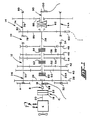
- Figure 2 is a schematic illustration of the semi-automatic shift implementation system for a mechanical transmission system of the present invention.
- FIG. 3 is a schematic illustration of an alternate control console for the system of Figure 2.
- Figure 4 is a flow chart illustrating the operation of the fuel control of the transmission system of the present invention.
- compound transmission is used to designate a change speed or change gear transmission having a multiple forward speed main transmission section and a multiple speed auxiliary transmission section connected in series whereby the selected gear reduction in the main transmission section may be compounded by further selected gear reduction in the auxiliary transmission section.
- "Synchronized clutch assembly” and words of similar import shall designate a clutch assembly utilized to nonrotatably couple a selected gear to a shaft by means of a positive clutch in which attempted engagement of said clutch is prevented until the members of the clutch are at substantially synchronous rotation in a relatively large capacity friction means are utilized with the clutch members and are sufficient, upon initiation of a clutch engagement, to cause the clutch members and all members rotating therewith to rotate at substantially synchronous speed.
- upshift shall mean the shifting from a lower speed gear ratio into a higher speed gear ratio.
- downshift shall mean the shifting from a higher speed gear ratio to a lower speed gear ratio.
- low speed gear shall all designate the gear ratio utilized for lowest forward speed operation in a transmission or transmission section, i.e., that set of gears having the highest ratio of reduction relative to the input shaft of the transmission.
- a "selected direction" of shifting will refer to selection of either single or multiple upshifting or downshifting from a particular gear ratio.
- Compound transmission 10 comprises a multiple speed main transmission section 12 connected in series with a range type auxiliary section 14.
- Transmission 10 is housed within a housing H and includes an input shaft 16 driven by a prime mover such as diesel engine E through a selectively disengaged, normally engaged friction master clutch C having an input or driving portion 18 drivingly connected to the engine crankshaft 20 and a driven portion 22 rotatably fixed to the transmission input shaft 16.
- a prime mover such as diesel engine E
- a selectively disengaged, normally engaged friction master clutch C having an input or driving portion 18 drivingly connected to the engine crankshaft 20 and a driven portion 22 rotatably fixed to the transmission input shaft 16.
- the engine E is fuel throttle controlled by a normally manually controlled throttle device (T) and a sensor for sensing the manual setting thereof and the master clutch C is manually controlled by a clutch pedal (not shown) or the like.
- An input shaft brake B operated by overtravel of the clutch pedal, is preferably provided to provide quicker upshifting as is well known in the prior art.
- Fueling of the engine and/or signals indicative of throttle position may be by data links F such as defined in the SAE J1922 protocol.
- the input shaft 16 carries an input gear 24 for simultaneously driving a plurality of substantially identical countershaft assemblies 26 and 26A at substantially identical rotational speeds.
- the two substantially identical countershaft assemblies are provided on diametrically opposite sides of mainshaft 28 which is generally coaxially aligned with the input shaft 16.
- Each of the countershaft assemblies comprises a countershaft 30 supported by bearings 32 and 34 in housing H, only a portion of which is schematically illustrated.
- Each of the countershafts is provided with an identical grouping of countershaft gears 38, 40, 42, 44, 46 and 48, fixed for rotation therewith.
- a plurality of mainshaft gears 50, 52, 54, 56 and 58 surround the mainshaft 28 and are selectively clutchable, one at a time, to the mainshaft 28 for rotation therewith by sliding clutch collars 60, 62 and 64 as is well known in the prior art.
- Clutch collar 60 may also be utilized to clutch input gear 24 to mainshaft 28 to provide a direct drive relationship between input shaft 16 and mainshaft 28.
- clutch collars 60, 62 and 64 are axially positioned by means of shift forks associated with the shift housing assembly 70, as well known in the prior art.
- Clutch collars 60, 62 and 64 may be of the well known acting nonsynchronized double acting jaw clutch type.
- Shift housing or actuator 70 is actuated by compressed fluid, such as compressed air, and is of the type automatically controllable by a control unit as may be seen by reference to U.S. Pat. Nos. 4,445,393; 4,555,959; 4,361,060; 4,722,237 and 2,931,237.
- Mainshaft gear 58 is the reverse gear and is in continuous meshing engagement with countershaft gears 48 by means of conventional intermediate idler gears (not shown). It should also be noted that while main transmission section 12 does provide five selectable forward speed ratios, the lowest forward speed ratio, namely that provided by drivingly connecting mainshaft drive gear 56 to mainshaft 28, is often of such a high gear reduction it has to be considered a low or "creeper" gear which is utilized only for starting of a vehicle under severe conditions and, is not usually utilized in the high transmission range. Accordingly, while main transmission section 12 does provide five forward speeds, it is usually referred to as a "four plus one" main section as only four of the forward speeds are compounded by the auxiliary range transmission section 14 utilized therewith.
- Jaw clutches 60, 62, and 64 are three-position clutches in that they may be positioned in the centered, nonengaged position as illustrated, or in a fully rightwardly engaged or fully leftwardly engaged position by means of a shift lever 72. As is well known, only one of the clutches 60, 62 and 64 is engageable at a given time and main section interlock means (not shown) are provided to lock the other clutches in the neutral condition.
- Auxiliary transmission range section 14 includes two substantially identical auxiliary countershaft assemblies 74 and 74A, each comprising an auxiliary countershaft 76 supported by bearings 78 and 80 in housing H and carrying two auxiliary section countershaft gears 82 and 84 for rotation therewith.
- Auxiliary countershaft gears 82 are constantly meshed with and support range/output gear 86 while auxiliary section countershaft gears 84 are constantly meshed with output gear 88 which is fixed to transmission output shaft 90.
- a two-position synchronized jaw clutch assembly 92 which is axially positioned by means of a shift fork (not shown) and the range section shifting actuator assembly 96, is provided for clutching either gear 86 to mainshaft 28 for low range operation or gear 88 to mainshaft 28 for direct or high range operation of the compound transmission 10.
- the "shift pattern" for compound range type transmission 10 is schematically illustrated in Figure 1A.
- Range section actuator 96 may be of the type illustrated in U.S. Pat. Nos. 3,648,546; 4,440,037 and 4,614,126.
- range type auxiliary section 14 is illustrated as a two-speed section utilizing spur or helical type gearing, it is understood that the present invention is also applicable to range type transmissions utilizing combined splitter/range type auxiliary sections, having three or more selectable range ratios and/or utilizing planetary type gearing. Also, any one or more of clutches 60, 62 or 64 may be of the synchronized jaw clutch type and transmission sections 12 and/or 14 may be of the single countershift type.
- an input shaft speed sensor and an output shaft speed sensor 100 are utilized.
- a sensor 102 for sensing the rotational speed of auxiliary section countershaft gear 82 may be utilized.
- the rotational speed of gear 82 is, of course, a known function of the rotational speed of mainshaft 28 and, if clutch 92 is engaged in a known position, a function of the rotational speed of output shaft 90.
- Control system 104 for a mechanical transmission system of the present invention is schematically illustrated in Figure 2.
- Control system 104 in addition to the mechanical transmission system 10 described above, includes an electronic control unit 106, preferably microprocessor based, for receiving input signals from the input shaft speed sensor 98, from the output shaft speed sensor 100 (or, alternatively, the mainshaft speed sensor 102) and from the driver control console 108.
- the ECU 106 may also receive inputs from an auxiliary section position sensor 110.
- the ECU is effective to process the inputs in accordance with predetermined logic rules to issue command output signals to a transmission operator, such as solenoid manifold 112 which controls the mainsection section actuator 70, the auxiliary section actuator 96, the engine fuel actuator data link F, and to the driver control console 108.
- a transmission operator such as solenoid manifold 112 which controls the mainsection section actuator 70, the auxiliary section actuator 96, the engine fuel actuator data link F, and to the driver control console 108.
- the data link F carries signals to the engine control corresponding to the operator's manual setting of the throttle pedal.
- the driver control console allows the operator to manually select a shift in a given direction or to neutral from the-currently engaged ratio, or to select a semi-automatic preselect mode of operation, and provides a display for informing the operator of the current mode of operation (automatic or manual preselection of shifting), the current transmission operation condition (forward, reverse or neutral) and of any ratio change or shift (upshift, downshift or shift to neutral) which has been preselected but not yet implemented.
- Console 108 includes three indicator lights 114, 116 and 118 which will be lit to indicate that the transmission 10 is in a forward drive, neutral or reverse drive, respectively, condition.
- the console also includes three selectively lighted push buttons 120, 122, and 124 which allow the operator to select an upshift, automatic preselection mode or a downshift, respectively.
- a push button 126 allows selection of a shift into neutral.
- buttons 120, 122, 124 or 126 may be cancelled (prior to execution in the case of buttons 120, 124 and 126) by redepressing the buttons.
- multiple depressions of buttons 120 and 124 may be used as commands for skip shifts.
- the buttons and lighted buttons can be replaced by other selection means, such as a toggle switch and/or a toggle switch and light or other indicia member.
- a separate button or switch for selection of reverse may be provided or reverse may be selected as a downshift from neutral. Also, neutral may be selected as an upshift from reverse or as a downshift from low.
- buttons 120 or button 124 are buttons 120 or button 124 as appropriate.
- the selected button will then be lighted until the selected shift is implemented or until the selection is cancelled.
- the upshift button may be lit and remain lit until an upshift is selected by pushing the button.
- the manifold 112 is preselected to cause actuator 70 to be biased to shift main transmission section 12 into neutral. This is accomplished by the operator causing a torque break or reversal by manually momentarily decreasing and/or increasing the supply of fuel to the engine and/or disengaging the master clutch C. This allows operator to determine when a shift sequence will begin. As the transmission is shifted into neutral, and neutral is verified by the ECU (neutral sensed for a period of time such as 1.5 seconds), the neutral condition indicia button 116 is lighted. If the selected shift is a compound shift, i.e.
- the ECU will issue command output signals to manifold 112 to cause the auxiliary section actuator 96 to complete the range shift after neutral is sensed in the front box.
- the ECU When the range auxiliary section is engaged in the proper ratio, the ECU will calculate or otherwise determine, and continue to update, an enabling range or band of input shaft speeds, based upon sensed output shaft (vehicle) speed and the ratio to be engaged, which will result in an acceptably synchronous engagement of the ratio to be engaged.
- the ECU 106 will then issue commands over the data link F to vary the fueling of the engine to achieve synchronous conditions, i.e. cause the input shaft speed to fall within the acceptable range.
- the ECU 106 Upon achieving synchronous conditions the ECU 106 will issue command output signals to manifold 112 to cause actuator 70 to engage the mainsection ratio to be engaged.
- the actuator will respond very quickly not requiring the operator to maintain the input shaft speed within the acceptable range for an extended period of time.
- selection button 126 To select a shift into transmission neutral, selection button 126 is pushed. Indicating light 116 will flash until the ECU confirms that neutral is obtained at which time the light 116 will assume a continuously
- the ECU In the automatic preselection mode of operation, selected by use of lighted push button 122, the ECU will, based upon stored logic rules, currently engaged ratio (which may be calculated by comparing input shaft to output shaft speed) and output shaft speed, determine if an upshift or a downshift is required and preselect same. The operator is informed that an upshift or downshift is preselected and will be semi-automatically implemented by a command output signal from ECU 106 causing either lighted push button 120 or lighted push button 124 to flash and/or an audible shift alert signal. The operator may initiate semi-automatic implementation of the automatically preselected shift as indicated above or may cancel the automatic mode by depression of push button 122.
- neutral condition indication light 116 may be eliminated and neutral selection push button 126 replaced by a lighted push button.
- An alternate driver control and display console 130 may be seen by reference to Figure 3.
- a joy stick 132 is movable against a resilient bias from its centered position to select upshifts, downshifts, a shift to neutral or the automatic preselect mode by movement up, down, leftward or rightward, respectively, as indicated.
- Indicia lights 134 and 136 are lighted to indicate an upshift or downshift, respectively, is preselected.
- Indicia lights 138 and 140, respectively, are lighted to indicate a vehicle forward or reverse, respectively, mode of operation.
- Indicia light 142 is steadily lighted to indicate a transmission neutral condition and is flashed to indicate a preselected but not yet confirmed neutral condition.
- Indicia light 144 is lighted to indicate system 104 is operating in the automatic preselection mode of operation.
- a relatively simple and inexpensive semi-automatic shift implementation control system (104)/method for a mechanical transmission system 10 requiring only a transmission shift actuator (112/70/96) and two rotational speed sensors (98/100) to be added to vehicle mechanical transmission system including an electronically controlled engine is provided.
- An electronic control unit 106 for receiving the two speed inputs, and inputs from an operator's console and for issuing command outsignals to the actuators, the engine data link, and to the display portion of the operator's console is also provided.
- the system semi-automatically executes manually or automatically preselected shifts requiring the operator to only initiate the process by causing a torque break.
Landscapes
- Engineering & Computer Science (AREA)
- Chemical & Material Sciences (AREA)
- Combustion & Propulsion (AREA)
- Mechanical Engineering (AREA)
- Transportation (AREA)
- General Engineering & Computer Science (AREA)
- Automation & Control Theory (AREA)
- Control Of Transmission Device (AREA)
- Control Of Driving Devices And Active Controlling Of Vehicle (AREA)
Claims (3)
- Procédé de commande pour commander l'exécution semi-automatique des changements de vitesses sélectionnés d'un système de transmission (104) mécanique de changement de vitesses semi-automatique, le système de transmission comprenant un moteur commandé par papillon des gaz (E), un contrôleur de carburant pour contrôler l'alimentation en carburant du moteur, une transmission mécanique (10) de changement de vitesses, à plusieurs vitesses, un embrayage à friction principal interposé de manière à assurer un entraînement entre le moteur et la transmission, un premier capteur (98) fournissant un signal d'entrée indiquant la vitesse de rotation de l'arbre d'entrée de la transmission (16), un deuxième capteur (100) fournissant un signal d'entrée indicateur de la vitesse de rotation d'un arbre de transmission (90) pouvant entrer en rotation indépendamment par rapport à l'arbre d'entrée dans au moins certaines conditions de fonctionnement de la transmission, un troisième capteur (THD) fournissant un signal déterminé en fonction de la position du dispositif de papillon des gaz à commande manuelle (T), un dispositif de commande pouvant être commandé de manière non manuelle (70/96) pour commander le changement de vitesses de la transmission, des moyens de sélection (120, 124/132) pour sélectionner un passage à une vitesse supérieure ou un passage à une vitesse inférieure à partir d'un rapport en prise ou point mort à un rapport sélectionné et fournissant un signal d'entrée indiquant ce dernier, et une unité centrale de traitement (106) recevant lesdits signaux d'entrée et les traitant en fonction de règles logiques prédéterminées pour émettre des signaux de sortie de commande, ledit procédé étant caractérisé en ce qu'il :(a) répond à la sélection détectée d'un changement de vitesses à partir d'un rapport en prise en émettant des signaux de sortie de commande à destination dudit dispositif de commande pour solliciter la transmission pour assurer son passage au point mort et à destination dudit contrôleur de carburant pour alimenter le moteur en carburant en fonction de la position manuelle du papillon des gaz (THD) ; et(b) répond à (i) une sélection détectée d'un changement de vitesse pour passer d'un rapport en prise à un rapport sélectionné, et (ii) une confirmation d'un état de point mort de la transmission en émettant premièrement des signaux de sortie de commande à destination dudit contrôleur de carburant pour réaliser pratiquement une synchronisation de la transmission, et deuxièmement ensuite, en émettant des signaux de sortie de commande à destination du dispositif de commande de la transmission pour provoquer le passage de la transmission dans le rapport sélectionné.
- Procédé de commande selon la revendication 1, selon lequel lesdits changements de vitesses sélectionnés sont sélectionnés manuellement.
- Procédé de commande selon la revendication 1, selon lequel lesdits changements de vitesses sélectionnés sont sélectionnés automatiquement.
Applications Claiming Priority (2)
| Application Number | Priority Date | Filing Date | Title |
|---|---|---|---|
| US904936 | 1992-06-26 | ||
| US07/904,936 US5261298A (en) | 1992-06-26 | 1992-06-26 | Enhanced semi-automated mechanical transmission system |
Publications (2)
| Publication Number | Publication Date |
|---|---|
| EP0576156A1 EP0576156A1 (fr) | 1993-12-29 |
| EP0576156B1 true EP0576156B1 (fr) | 1997-07-30 |
Family
ID=25420000
Family Applications (1)
| Application Number | Title | Priority Date | Filing Date |
|---|---|---|---|
| EP93304171A Expired - Lifetime EP0576156B1 (fr) | 1992-06-26 | 1993-05-28 | Système de transmission mécanique semi-automatique améliorisée |
Country Status (8)
| Country | Link |
|---|---|
| US (1) | US5261298A (fr) |
| EP (1) | EP0576156B1 (fr) |
| JP (1) | JPH06199159A (fr) |
| CA (1) | CA2099161C (fr) |
| CZ (1) | CZ286003B6 (fr) |
| DE (1) | DE69312593T2 (fr) |
| ES (1) | ES2106966T3 (fr) |
| PL (1) | PL299388A1 (fr) |
Cited By (1)
| Publication number | Priority date | Publication date | Assignee | Title |
|---|---|---|---|---|
| DE19904129C1 (de) * | 1999-02-03 | 2000-02-24 | Mannesmann Sachs Ag | Verfahren zur Durchführung von Schaltvorgängen bei einem Antriebssystem |
Families Citing this family (11)
| Publication number | Priority date | Publication date | Assignee | Title |
|---|---|---|---|---|
| JP3013588B2 (ja) * | 1992-04-10 | 2000-02-28 | 三菱自動車工業株式会社 | 車両用自動変速機の変速制御方法 |
| US5429559A (en) * | 1993-09-22 | 1995-07-04 | Eaton Corporation | Forced engagement logic |
| EP0681120B1 (fr) * | 1994-05-05 | 1999-03-03 | Eaton Corporation | Régulation du verrouillage de la marche arrière |
| GB9412805D0 (en) * | 1994-06-25 | 1994-08-17 | Eaton Corp | Engagement fault degraded mode control |
| DE19601291A1 (de) * | 1996-01-16 | 1997-07-24 | Jochen Dauer Racing Fa | Mechanisches Schaltgetriebe für Kraftfahrzeuge und Verfahren für elektronisches oder manuell auslösbares Schalten |
| US5735771A (en) * | 1996-04-30 | 1998-04-07 | Eaton Corporation | Semi-automatic shift implementation |
| DE69713450T2 (de) * | 1996-04-30 | 2003-01-23 | Eaton Corp | Schaltabsichtvorrichtung für halbautomatische Schaltdurchführung |
| US5904635A (en) * | 1997-08-07 | 1999-05-18 | Eaton Corporation | Partially automated lever-shifted mechanical transmission system |
| US6243636B1 (en) | 1997-08-13 | 2001-06-05 | Zf Meritor, Llc | Two stage torque control method for a vehicle transmission |
| US5980424A (en) * | 1997-10-21 | 1999-11-09 | Detroit Diesel Corporation | Torque dithering method for controlling a vehicle transmission |
| DE102013218365A1 (de) * | 2013-09-13 | 2015-03-19 | Zf Friedrichshafen Ag | Verfahren zur Durchführung der Synchronisierung eines formschlüssigen Schaltelementes bei einer Schaltung im Schubbetrieb bei positivem Motoreingriff oder positiver Drehzahlführung |
Family Cites Families (13)
| Publication number | Priority date | Publication date | Assignee | Title |
|---|---|---|---|---|
| FR1366732A (fr) * | 1960-05-05 | 1964-07-17 | Système de commande automatique d'accouplement et de mécanisme de changement de vitesse pour véhicules automobiles | |
| US4361060A (en) * | 1978-01-24 | 1982-11-30 | Smyth Robert Ralston | Mechanical automatic transmission |
| DE3045840A1 (de) * | 1980-12-05 | 1982-07-08 | Volkswagenwerk Ag, 3180 Wolfsburg | Einrichtung zum kupplungs- und synchronisiergliederfreien schalten eines stufenwechselgetriebes von fahrzeugantrieben |
| GB8418749D0 (en) * | 1984-07-23 | 1984-08-30 | Eaton Ltd | Semi-automatic transmission control |
| US4850236A (en) * | 1987-11-20 | 1989-07-25 | Eaton Corporation | Vehicle drive line shift control system and method |
| DE3832971A1 (de) * | 1988-09-29 | 1990-04-12 | Porsche Ag | Anzeigevorrichtung fuer ein automatisches kraftfahrzeuggetriebe |
| EP0392732A1 (fr) * | 1989-04-14 | 1990-10-17 | Eaton Corporation | Dispositif de commande de démarrage pour une transmission mécanique automatique |
| US4991099A (en) * | 1989-06-19 | 1991-02-05 | Eaton Corporation | Control system/method for controlling shifting of a range type compound transmission using input shaft and mainshaft speed sensors |
| US5053961A (en) * | 1989-06-19 | 1991-10-01 | Eaton Corporation | Semi-automatic shift implementation for mechanical transmission system |
| US5053962A (en) * | 1989-06-19 | 1991-10-01 | Eaton Corporation | Automatic shift preselection mode for mechanical transmission system with semi-automatic shift implementation |
| US5053959A (en) * | 1989-06-19 | 1991-10-01 | Eaton Corporation | Control system and method for sensing and indicating neutral in a semi-automatic mechanical transmission system |
| US5089962A (en) * | 1990-08-17 | 1992-02-18 | Eaton Corporation | Unexpected n logic |
| JPH04215531A (ja) * | 1990-12-10 | 1992-08-06 | Honda Motor Co Ltd | 変速制御装置 |
-
1992
- 1992-06-26 US US07/904,936 patent/US5261298A/en not_active Expired - Lifetime
-
1993
- 1993-05-28 DE DE69312593T patent/DE69312593T2/de not_active Expired - Fee Related
- 1993-05-28 ES ES93304171T patent/ES2106966T3/es not_active Expired - Lifetime
- 1993-05-28 EP EP93304171A patent/EP0576156B1/fr not_active Expired - Lifetime
- 1993-06-18 PL PL29938893A patent/PL299388A1/xx unknown
- 1993-06-18 JP JP5172467A patent/JPH06199159A/ja active Pending
- 1993-06-25 CA CA002099161A patent/CA2099161C/fr not_active Expired - Fee Related
- 1993-06-25 CZ CZ931275A patent/CZ286003B6/cs not_active IP Right Cessation
Cited By (1)
| Publication number | Priority date | Publication date | Assignee | Title |
|---|---|---|---|---|
| DE19904129C1 (de) * | 1999-02-03 | 2000-02-24 | Mannesmann Sachs Ag | Verfahren zur Durchführung von Schaltvorgängen bei einem Antriebssystem |
Also Published As
| Publication number | Publication date |
|---|---|
| CA2099161A1 (fr) | 1993-12-27 |
| CZ127593A3 (en) | 1995-04-12 |
| ES2106966T3 (es) | 1997-11-16 |
| PL299388A1 (en) | 1993-12-27 |
| DE69312593D1 (de) | 1997-09-04 |
| CZ286003B6 (cs) | 1999-12-15 |
| CA2099161C (fr) | 1999-04-06 |
| EP0576156A1 (fr) | 1993-12-29 |
| JPH06199159A (ja) | 1994-07-19 |
| US5261298A (en) | 1993-11-16 |
| DE69312593T2 (de) | 1998-03-12 |
Similar Documents
| Publication | Publication Date | Title |
|---|---|---|
| US5053961A (en) | Semi-automatic shift implementation for mechanical transmission system | |
| EP0404387B1 (fr) | Présélection automatique de changement de vitesse pour transmission mécanique avec un changement de vitesse semi-automatique | |
| EP0471491B1 (fr) | Commande de mode de changement de vitesse pour transmission mécanique avec réalisation semi-automatique de changement et avec des modes de préselection manuelle et automatique | |
| US5089965A (en) | Shift prohibiting for automatic shift preselection mode for mechanical transmission system with semi-automatic shift implementation | |
| US5053959A (en) | Control system and method for sensing and indicating neutral in a semi-automatic mechanical transmission system | |
| US5444623A (en) | Reengagement control/method for mechanical transmission system with automatic shift implementation | |
| CA2020109C (fr) | Systeme de commande de changement de vitesse et methode relative au systeme de transmission mecanique | |
| CA2049239C (fr) | Commande de vitesse logique | |
| US5441463A (en) | Selected speed ratio not-engaged range section recovery by shifting to a non-selected speed ratio and if permitted, shifting to the selected speed ratio | |
| EP0413412B1 (fr) | Système de réglage pour exécuter un changement de vitesse semi-automatique | |
| US5315514A (en) | Unexpected N logic for vehicular semi-automated mechanical transmissions | |
| US4991099A (en) | Control system/method for controlling shifting of a range type compound transmission using input shaft and mainshaft speed sensors | |
| EP0576156B1 (fr) | Système de transmission mécanique semi-automatique améliorisée | |
| CA2131069C (fr) | Systeme et procede servant a changer de facon rapide et repetee les vitesses d'une transmission | |
| EP0565257A1 (fr) | Système de transmission mécanique semi-automatique |
Legal Events
| Date | Code | Title | Description |
|---|---|---|---|
| PUAI | Public reference made under article 153(3) epc to a published international application that has entered the european phase |
Free format text: ORIGINAL CODE: 0009012 |
|
| AK | Designated contracting states |
Kind code of ref document: A1 Designated state(s): DE ES FR GB IT NL SE |
|
| 17P | Request for examination filed |
Effective date: 19940221 |
|
| 17Q | First examination report despatched |
Effective date: 19951204 |
|
| GRAG | Despatch of communication of intention to grant |
Free format text: ORIGINAL CODE: EPIDOS AGRA |
|
| GRAH | Despatch of communication of intention to grant a patent |
Free format text: ORIGINAL CODE: EPIDOS IGRA |
|
| GRAH | Despatch of communication of intention to grant a patent |
Free format text: ORIGINAL CODE: EPIDOS IGRA |
|
| GRAA | (expected) grant |
Free format text: ORIGINAL CODE: 0009210 |
|
| AK | Designated contracting states |
Kind code of ref document: B1 Designated state(s): DE ES FR GB IT NL SE |
|
| REF | Corresponds to: |
Ref document number: 69312593 Country of ref document: DE Date of ref document: 19970904 |
|
| REG | Reference to a national code |
Ref country code: ES Ref legal event code: FG2A Ref document number: 2106966 Country of ref document: ES Kind code of ref document: T3 |
|
| ET | Fr: translation filed | ||
| PLBE | No opposition filed within time limit |
Free format text: ORIGINAL CODE: 0009261 |
|
| STAA | Information on the status of an ep patent application or granted ep patent |
Free format text: STATUS: NO OPPOSITION FILED WITHIN TIME LIMIT |
|
| 26N | No opposition filed | ||
| REG | Reference to a national code |
Ref country code: GB Ref legal event code: IF02 |
|
| PGFP | Annual fee paid to national office [announced via postgrant information from national office to epo] |
Ref country code: NL Payment date: 20050407 Year of fee payment: 13 |
|
| PGFP | Annual fee paid to national office [announced via postgrant information from national office to epo] |
Ref country code: FR Payment date: 20050517 Year of fee payment: 13 |
|
| PGFP | Annual fee paid to national office [announced via postgrant information from national office to epo] |
Ref country code: ES Payment date: 20050520 Year of fee payment: 13 |
|
| PG25 | Lapsed in a contracting state [announced via postgrant information from national office to epo] |
Ref country code: ES Free format text: LAPSE BECAUSE OF NON-PAYMENT OF DUE FEES Effective date: 20060529 |
|
| PGFP | Annual fee paid to national office [announced via postgrant information from national office to epo] |
Ref country code: IT Payment date: 20060531 Year of fee payment: 14 |
|
| PG25 | Lapsed in a contracting state [announced via postgrant information from national office to epo] |
Ref country code: NL Free format text: LAPSE BECAUSE OF NON-PAYMENT OF DUE FEES Effective date: 20061201 |
|
| NLV4 | Nl: lapsed or anulled due to non-payment of the annual fee |
Effective date: 20061201 |
|
| REG | Reference to a national code |
Ref country code: FR Ref legal event code: ST Effective date: 20070131 |
|
| REG | Reference to a national code |
Ref country code: ES Ref legal event code: FD2A Effective date: 20060529 |
|
| PG25 | Lapsed in a contracting state [announced via postgrant information from national office to epo] |
Ref country code: FR Free format text: LAPSE BECAUSE OF NON-PAYMENT OF DUE FEES Effective date: 20060531 |
|
| PGFP | Annual fee paid to national office [announced via postgrant information from national office to epo] |
Ref country code: DE Payment date: 20080530 Year of fee payment: 16 |
|
| PGFP | Annual fee paid to national office [announced via postgrant information from national office to epo] |
Ref country code: SE Payment date: 20080505 Year of fee payment: 16 |
|
| PGFP | Annual fee paid to national office [announced via postgrant information from national office to epo] |
Ref country code: GB Payment date: 20080407 Year of fee payment: 16 |
|
| PG25 | Lapsed in a contracting state [announced via postgrant information from national office to epo] |
Ref country code: IT Free format text: LAPSE BECAUSE OF NON-PAYMENT OF DUE FEES Effective date: 20070528 |
|
| GBPC | Gb: european patent ceased through non-payment of renewal fee |
Effective date: 20090528 |
|
| PG25 | Lapsed in a contracting state [announced via postgrant information from national office to epo] |
Ref country code: GB Free format text: LAPSE BECAUSE OF NON-PAYMENT OF DUE FEES Effective date: 20090528 |
|
| PG25 | Lapsed in a contracting state [announced via postgrant information from national office to epo] |
Ref country code: DE Free format text: LAPSE BECAUSE OF NON-PAYMENT OF DUE FEES Effective date: 20091201 |
|
| PG25 | Lapsed in a contracting state [announced via postgrant information from national office to epo] |
Ref country code: SE Free format text: LAPSE BECAUSE OF NON-PAYMENT OF DUE FEES Effective date: 20090529 |