EP0575657A1 - Method and machine for finishing a bore in workpieces - Google Patents
Method and machine for finishing a bore in workpieces Download PDFInfo
- Publication number
- EP0575657A1 EP0575657A1 EP92110815A EP92110815A EP0575657A1 EP 0575657 A1 EP0575657 A1 EP 0575657A1 EP 92110815 A EP92110815 A EP 92110815A EP 92110815 A EP92110815 A EP 92110815A EP 0575657 A1 EP0575657 A1 EP 0575657A1
- Authority
- EP
- European Patent Office
- Prior art keywords
- infeed
- workpiece
- delivery
- tool
- force
- Prior art date
- Legal status (The legal status is an assumption and is not a legal conclusion. Google has not performed a legal analysis and makes no representation as to the accuracy of the status listed.)
- Granted
Links
Images
Classifications
-
- B—PERFORMING OPERATIONS; TRANSPORTING
- B24—GRINDING; POLISHING
- B24B—MACHINES, DEVICES, OR PROCESSES FOR GRINDING OR POLISHING; DRESSING OR CONDITIONING OF ABRADING SURFACES; FEEDING OF GRINDING, POLISHING, OR LAPPING AGENTS
- B24B33/00—Honing machines or devices; Accessories therefor
- B24B33/10—Accessories
- B24B33/105—Honing spindles; Devices for expanding the honing elements
-
- G—PHYSICS
- G05—CONTROLLING; REGULATING
- G05B—CONTROL OR REGULATING SYSTEMS IN GENERAL; FUNCTIONAL ELEMENTS OF SUCH SYSTEMS; MONITORING OR TESTING ARRANGEMENTS FOR SUCH SYSTEMS OR ELEMENTS
- G05B19/00—Programme-control systems
- G05B19/02—Programme-control systems electric
- G05B19/18—Numerical control [NC], i.e. automatically operating machines, in particular machine tools, e.g. in a manufacturing environment, so as to execute positioning, movement or co-ordinated operations by means of programme data in numerical form
- G05B19/416—Numerical control [NC], i.e. automatically operating machines, in particular machine tools, e.g. in a manufacturing environment, so as to execute positioning, movement or co-ordinated operations by means of programme data in numerical form characterised by control of velocity, acceleration or deceleration
- G05B19/4163—Adaptive control of feed or cutting velocity
Definitions
- the invention relates to a method for finishing bores in workpieces using a tool with expandable work parts such as honing stones or honing stones, according to the preamble of claim 1, and a machine for performing the method, in particular a honing machine.
- the feed path is therefore proportional to the inner diameter of the calibration ring, and the feed force depends exclusively on the strong spring, the preload of which cannot be adjusted.
- the invention is based on the object of determining the infeed by means of the presetting of the infeed path in such a way that the dimensional accuracy of the finished bore is significantly improved.
- the infeed path is preset in accordance with a certain infeed force that occurs when the finished dimension of the bore is reached.
- This feed force can change according to the cutting behavior of the working parts of the tool and also due to other circumstances, for example due to material differences in the material of the workpieces and their different strength.
- the delivery path and thus the delivery force are adapted to the different conditions.
- the feed path when expanding the working parts of the tool in the sample workpiece is determined in accordance with a feed force, which is determined by measuring the feed force when the The finished dimension of the hole was determined on a previously machined workpiece.
- this measured feed force changes as a result of changed machining conditions - such as material properties or elasticity behavior of the workpiece - the feed path is changed, i.e. the infeed force last measured during machining on the previous workpiece is decisive when machining the next workpiece.
- the feed path can also be changed to take tool wear into account, whereby the last measured feed force is also decisive.
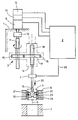
- the drawing shows a honing machine 1, which contains a numerical control 2.
- This controller is connected to a delivery device 3, which is connected to a honing tool 5 via a load cell 4.
- the honing tool 5 is located in a calibration ring 8 arranged coaxially to its tool axis 6 and above a workpiece 7.
- the calibration ring corresponds to a sample workpiece. In its place, a workpiece machined to an exact finished dimension can also be provided as a so-called masterpiece.
- the delivery device 3 includes a stationary DC motor 9, which drives a polygon shaft 11 via a coupling 10.
- the rotational position of the motor shaft is over a rotary encoder 12 controlled.
- the speed of the shaft is controlled by means of a tachometer 13.
- the polygon shaft 11 serves as a drive shaft for a feed gear 14, which contains a drive gear 15, which is arranged on the shaft 11 in a rotationally fixed and axially displaceable manner, and a gear 16 driven by it, which is arranged coaxially to the tool axis 6.
- a threaded bore 17 which is coaxial with the tool axis 6 and into which a threaded spindle 18 engages.
- the threaded spindle 18 is secured against rotation and, when the gear 16 rotates, performs an axial movement corresponding to the thread pitch, which is transmitted via the load cell 4 directly to an infeed rod 19 which engages in the honing tool 5.
- a truncated cone body 21 formed integrally with the feed rod moves along wedge surfaces 22 honing stone carriers 23, to which honing stones 25 are fastened.
- the honing stones are therefore fed radially in the direction of the arrows 24 against the inner wall of the calibration ring 18 and pressed against them.
- the honing machine is started by means of the numerical control 2.
- the honing tool 5 moves into the calibration ring 8. This stroke movement is ended after reaching the position shown in the drawing.
- the delivery device 3 is now started.
- the honing stones are first fed in rapid traverse in the direction of the arrows 24 until they abut the inner wall of the calibration ring 8 and a predeterminable application torque is reached.
- the express delivery is stopped and immediately afterwards the honing stones are one certain small amount deferred to mechanically relax the entire delivery system.
- a fine infeed is initiated, which corresponds to the later infeed of the honing stones in the workpiece for machining.
- the honing stones are thereby pressed against the inner wall of the calibration ring 8.
- the delivery path has the effect of a delivery force, which is measured continuously by the load cell 4.
- the measured values are fed as signals to the numerical control 2 via a line 26.
- a value of the delivery person preselected by input is stored.
- delivery is terminated.
- the point of the delivery route that is then reached is stored in the controller 2 as a "finished dimension".
- the honing stones are reset by means of the feed device 3 by an amount programmable in the control 2, so that the honing tool 5 can now be inserted into the bore of the workpiece 7.
- the honing operation begins in the usual way. It is automatically ended via the numerical control 2 at the moment when the stored "finished dimension" point is reached.
- the infeed force on the workpiece 7 is continuously measured during the honing process by means of the load cell 4 and fed to the controller 2 as a signal via the line 26.
- the honing stones 25 are reset by means of the feed device 3, and the honing tool 5 is moved out of the hole in the workpiece 7 until the honing stones are again completely within the calibration ring 8.
- the delivery route can be readjusted.
- the value of the infeed force, the immediately before the finished dimension was reached, compared with the stored value. If there are deviations, the measured value is saved and the previous value is deleted or overwritten. This storage value of the delivery worker is now evaluated for checking and possibly re-adjusting the delivery route.
- the honing stones are fed against the wall of the calibration ring.
- the dimensional adjustment is made depending on the infeed force measured for each workpiece shortly before the "finished dimension” point is reached.
- the newly set “finished dimension” point of the delivery route is retained until the measured value deviates from the stored value of the delivery worker.
- the infeed force measured shortly before reaching the "finished dimension” point that is to say shortly before switching off, is continuously compared with the last stored value of the infeed force for each workpiece that is being processed, and is expedient if one is exceeded the newer value is saved and the older value is deleted or overwritten. Every time a new value for the delivery force is saved, a new dimension adjustment is carried out.
- the infeed path is thus determined when machining several workpieces in one work cycle in accordance with an actual value of the infeed force, which is determined by measuring the infeed force on a previously machined workpiece immediately before the infeed is switched off, entered as a comparison value in the numerical control 2 and at Deviation from the previously stored value, the last measured value of the delivery worker is stored; With this value of the infeed force, the "finished dimension" point of the infeed path is then reset in the calibration ring.
- a regular dimension adjustment in the calibration ring also takes wear of the honing stones into account. It is checked at predeterminable intervals in the calibration ring whether a change in the stored "finished dimension” point occurs with the stored delivery force. If the honing stones wear, the delivery path increases and a new "finished dimension” point is saved.
- the "finished dimension" point of the delivery path can be converted in the computer of the controller in accordance with the nominal diameter currently to be machined . This is conveniently done after a dimensional check in the calibration ring.
- several calibration rings or masterpieces assigned to the respective nominal diameters can also be used be provided, which can be stored in a magazine or revolver magazine and then brought into the path of movement of the tool according to the workpieces to be machined for the dimensional control. With such a device, a higher dimensional accuracy can be achieved than by converting the delivery route.
- the method according to the invention is also particularly suitable for the dimensionally accurate machining of workpieces which, due to their structural design, expand elastically under the machining forces.
- these elastic widenings are taken into account by specifying the feed path according to a measured feed force according to the invention, since they depend on a predetermined machining force in the masterpiece that behaves in the same way.
- the numerical control can also contain a correction program which evaluates the deviations from the specified values determined in the dimensional control in the calibration ring.
- the behavior of the workpieces under the machining forces can thus be taken into account even more precisely and the dimensional accuracy can accordingly be increased further.
- a measuring device for checking the dimensions of the finished workpieces.
- a measuring device consists, for example, of a pneumatic / electrical measuring device with a connected measuring mandrel, which is automatically inserted into the finished workpiece bore for measuring. The measured value is compared in a measuring device with the specified finished dimension, and a deviation is sent as a signal to the numerical control and evaluated there to correct the stored finished dimension.
- deviations in dimensions that occur can be recognized immediately and compensated for by the numerical control, so that the tolerances of the finished bores can be kept within very narrow limits.
Abstract
Description
Die Erfindung betrifft ein Verfahren zum Feinbearbeiten von Bohrungen in Werkstücken unter Verwendung eines Werkzeuges mit expandierbaren Arbeitsteilen wie Honleisten oder Honsteinen, nach dem Oberbegriff des Patentanspruches 1, sowie eine Maschine zur Durchführung des Verfahrens, insbesondere eine Honmaschine.The invention relates to a method for finishing bores in workpieces using a tool with expandable work parts such as honing stones or honing stones, according to the preamble of
Es ist bekannt, die expandierbaren Honleisten eines Honwerkzeuges vor der Bearbeitung der Werkstück-Bohrung innerhalb eines zur Bohrung koaxialen Eichringes bis an dessen Innenwandung zuzustellen, um damit den Zustellweg für die nachfolgende Honoperation festzulegen (US-A1 2 194 821). Bei dieser bekannten Maschine wird der Zustellweg dadurch bestimmt, daß die Honleisten innerhalb des Eichringes mittels einer federbelasteten Zustellstange expandiert werden, die mittels einer Zustelleinrichtung axial gegen die Federkraft verschoben wird, wobei der Zustellweg durch eine längs der Zustellstange axial verstellbare Hülse bestimmt wird, die eine Feder mit großer Federkraft enthält. Diese Feder wird beim Einfahren in die zu bearbeitende Bohrung zusammengedrückt und entspannt sich mit zunehmender Erweiterung der Bohrung. Der Zustellweg ist daher proportional zum Innendurchmesser des Eichringes, und die Zustellkraft ist ausschließlich von der starken Feder abhängig, deren Vorspannung nicht einstellbar ist. Mit dieser Zustellung mittels eines Eichringes kann zwar eine gewisse Maßgenauigkeit der Bohrung ohne zusätzliche Meßglieder erreicht werden, jedoch genügt die Genauigkeit hohen Anforderungen nicht. So können dabei nicht die unvermeidlichen Unterschiede im Schneidverhalten der Honsteine berücksichtigt werden, ebensowenig Materialunterschiede im Werkstoff der zu bearbeitenden Werkstücke. Ein weiterer Grund für die ungenügende Maßgenauigkeit ist die mechanische Festigkeit der Werkstücke, beispielsweise ihr Dehnverhalten unter den Bearbeitungskräften, das insbesondere bei dünnwandigen Werkstücken von Bedeutung ist.It is known to advance the expandable honing stones of a honing tool before machining the workpiece bore within a calibration ring coaxial with the bore up to its inner wall, in order to thereby determine the feed path for the subsequent honing operation (US Pat. No. 2,194,821). In this known machine the feed path is determined by the fact that the honing stones are expanded within the calibration ring by means of a spring-loaded feed rod which is axially displaced against the spring force by means of a feed device, the feed path being determined by a sleeve which is axially adjustable along the feed rod and which contains a spring with great spring force. This spring is compressed when entering the bore to be machined and relaxes as the bore increases. The feed path is therefore proportional to the inner diameter of the calibration ring, and the feed force depends exclusively on the strong spring, the preload of which cannot be adjusted. With this infeed by means of a calibration ring, a certain dimensional accuracy of the bore can be achieved without additional measuring elements, but the accuracy does not meet high requirements. Thus, the inevitable differences in the cutting behavior of the honing stones cannot be taken into account, nor can the material differences in the material of the workpieces to be machined. Another reason for the insufficient dimensional accuracy is the mechanical strength of the workpieces, for example their stretching behavior under the machining forces, which is particularly important in the case of thin-walled workpieces.
Es ist auch bekannt, die Zustellung von Honsteinen während der Bearbeitung einer Bohrung zu steuern, um den Anpreßdruck der Honsteine in Abhängigkeit von gemessenen Werten der Werkstückbohrung automatisch einzustellen (DE-C2 30 39 467). Damit sollen während der Bearbeitung auftretende und gemessene Formfehler der Bohrung korrigiert werden, wofür die Differenz von in zwei Ebenen der Bohrung gemessenen Durchmessern ermittelt und der Anpreßdruck entsprechend dem Meßergebnis verändert wird. Eine Voreinstellung des Zustellweges nach Maßgabe eines Muster-Werkstückes bzw. eines Eichringes ist bei diesem Verfahren nicht vorgesehen.It is also known to control the infeed of honing stones during the machining of a bore in order to automatically set the contact pressure of the honing stones as a function of measured values of the workpiece bore (DE-C2 30 39 467). This is intended to correct the shape errors of the bore that occur and are measured during machining, for which purpose the difference between diameters measured in two planes of the bore is determined and the contact pressure is changed in accordance with the measurement result. A presetting of the infeed path according to a sample workpiece or a calibration ring is not provided in this method.
Weiterhin ist ein Verfahren zum Honen von Bohrungen bekannt (EP-A1 0 390 938), bei dem die Druckkraft der an der Bohrungswandung anliegenden Honleisten während der Bearbeitung auf einen vorbestimmten Sollwert geregelt wird, der aus vorgegebenen Bohrungsmaßen und Bewegungsabläufen errechnet wurde. Diese Regelung ermöglicht ebenfalls keine Voreinstellung des Zustellweges, mit ihr soll vielmehr die Flächenpressung der Honleisten an die jeweiligen Gegebenheiten der zu bearbeitenden Bohrung angepaßt, insbesondere konstant gehalten werden.Furthermore, a method for honing bores is known (EP-A1 0 390 938), in which the compressive force of the honing stones lying against the bore wall is regulated during processing to a predetermined target value, which was calculated from predetermined bore dimensions and movement sequences. This regulation also does not allow any presetting of the feed path, but rather is intended to adapt the surface pressure of the honing stones to the particular circumstances of the bore to be machined, in particular to keep them constant.
Ausgehend von dem eingangs geschilderten Stand der Technik (US-A 2 194 821) liegt der Erfindung die Aufgabe zugrunde, die Zustellung mittels der Voreinstellung des Zustellweges derart zu bestimmen, daß die Maßgenauigkeit der fertigen Bohrung wesentlich verbessert wird.Starting from the prior art described at the beginning (US Pat. No. 2,194,821), the invention is based on the object of determining the infeed by means of the presetting of the infeed path in such a way that the dimensional accuracy of the finished bore is significantly improved.
Die Aufgabe wird gemäß der Erfindung mit den kennzeichnenden Merkmalen des Patentanspruches 1 gelöst.The object is achieved according to the invention with the characterizing features of
Bei diesem Verfahren wird der Zustellweg nach Maßgabe einer bestimmten Zustellkraft voreingestellt, die bei Erreichen des Fertigmaßes der Bohrung auftritt. Diese Zustellkraft kann sich entsprechend dem Schneidverhalten der Arbeitsteile des Werkzeuges und auch aufgrund weiterer Gegebenheiten ändern, beispielsweise durch Materialunterschiede im Werkstoff der Werkstücke und deren unterschiedliche Festigkeit. Bei dem erfindungsgemäßen Verfahren wird der Zustellweg und damit die Zustellkraft an die unterschiedlichen Bedingungen angepaßt. Hierfür ist insbesondere vorgesehen, daß der Zustellweg beim Expandieren der Arbeitsteile des Werkzeuges im Muster-Werkstück nach Maßgabe einer Zustellkraft bestimmt wird, die durch Messung der Zustellkraft bei Erreichen des Fertigmaßes der Bohrung an einem vorher bearbeiteten Werkstück ermittelt wurde.With this method, the infeed path is preset in accordance with a certain infeed force that occurs when the finished dimension of the bore is reached. This feed force can change according to the cutting behavior of the working parts of the tool and also due to other circumstances, for example due to material differences in the material of the workpieces and their different strength. In the method according to the invention, the delivery path and thus the delivery force are adapted to the different conditions. For this purpose, it is particularly provided that the feed path when expanding the working parts of the tool in the sample workpiece is determined in accordance with a feed force, which is determined by measuring the feed force when the The finished dimension of the hole was determined on a previously machined workpiece.
Ändert sich diese gemessene Zustellkraft infolge geänderter Zerspanbedingungen - wie Materialeigenschaften oder Elastizitätsverhalten des Werkstückes - so wird der Zustellweg geändert, d.h. die beim Zerspanen an dem vorhergehenden Werkstück zuletzt gemessene Zustellkraft ist bei der Bearbeitung des nächsten Werkstückes maßgebend. Der Zustellweg kann außerdem zur Berücksichtigung der Werkzeugabnutzung geändert werden, wobei ebenfalls die zuletzt gemessene Zustellkraft maßgeblich ist.If this measured feed force changes as a result of changed machining conditions - such as material properties or elasticity behavior of the workpiece - the feed path is changed, i.e. the infeed force last measured during machining on the previous workpiece is decisive when machining the next workpiece. The feed path can also be changed to take tool wear into account, whereby the last measured feed force is also decisive.
Weitere Merkmale der Erfindung ergeben sich aus den übrigen Ansprüchen.Further features of the invention result from the remaining claims.
Die Erfindung wird im folgenden anhand einer schematisch dargestellten Honmaschine näher erläutert.The invention is explained below with reference to a schematically illustrated honing machine.
Die Zeichnung zeigt eine Honmaschine 1, die eine numerische Steuerung 2 enthält. Diese Steuerung ist an eine Zustelleinrichtung 3 angeschlossen, die über eine Kraftmeßdose 4 mit einem Honwerkzeug 5 verbunden ist. In der zeichnerischen Darstellung befindet sich das Honwerkzeug 5 in einem koaxial zu seiner Werkzeugachse 6 und oberhalb eines Werkstückes 7 angeordneten Eichring 8. Der Eichring entspricht einem Muster-Werkstück. An seiner Stelle kann auch ein auf genaues Fertigmaß bearbeitetes Werkstück als sogenanntes Meisterwerkstück vorgesehen sein.The drawing shows a
Zu der Zustelleinrichtung 3 gehört ein ortsfest angeordneter Gleichstrommotor 9, der über eine Kupplung 10 eine Polygonwelle 11 antreibt. Die Drehlage der Motorwelle wird über einen Drehimpulsgeber 12 gesteuert. Die Drehzahl der Welle wird mittels eines Drehzahlmessers 13 geregelt. Die Polygonwelle 11 dient als Antriebswelle für ein Zustellgetriebe 14, das ein auf der Welle 11 drehfest und axial verschiebbar angeordnetes Antriebszahnrad 15 und ein von ihm angetriebenes Zahnrad 16 enthält, das koaxial zur Werkzeugachse 6 angeordnet ist. In dem Zahnrad 16 ist eine zur Werkzeugachse 6 koaxiale Gewindebohrung 17 vorgesehen, in die eine Gewindespindel 18 eingreift.The
Die Gewindespindel 18 ist gegen Verdrehen gesichert und führt bei Drehung des Zahnrades 16 eine der Gewindesteigung entsprechende axiale Bewegung aus, die über die Kraftmeßdose 4 direkt auf eine Zustellstange 19 übertragen wird, die in das Honwerkzeug 5 eingreift.The threaded
Bei einer axialen Abwärtsbewegung der Zustellstange 19 in Richtung des Pfeiles 20 verschiebt ein mit der Zustellstange einstückig ausgebildeter Kegelstumpfkörper 21 entlang von Keilflächen 22 Honsteinträger 23, an denen Honsteine 25 befestigt sind. Die Honsteine werden daher in Richtung der Pfeile 24 radial gegen die Innenwand des Eichringes 18 zugestellt und an sie angedrückt.In the event of an axial downward movement of the
Die Honmaschine wird mittels der numerischen Steuerung 2 gestartet. Dabei fährt das Honwerkzeug 5 in den Eichring 8 ein. Diese Hubbewegung wird nach Erreichen der in der Zeichnung dargestellten Lage beendet. Nunmehr wird die Zustelleinrichtung 3 gestartet. Dabei werden die Honsteine zunächst im Eilgang in Richtung der Pfeile 24 zugestellt, bis sie an der Innenwand des Eichringes 8 anliegen und ein vorgebbares Anlegemoment erreicht ist. Dann wird die Eilzustellung gestoppt und sofort anschließend werden die Honsteine um einen bestimmten geringen Betrag zurückgestellt, um das gesamte Zustellsystem mechanisch zu entspannen. Nunmehr wird eine Feinzustellung eingeleitet, die der späteren Zustellung der Honsteine im Werkstück für die Zerspanarbeit entspricht. Die Honsteine werden dadurch gegen die Innenwandung des Eichringes 8 gedrückt. Bei der weiteren Zustellung wirkt sich der Zustellweg als Zustellkraft aus, die fortlaufend von der Kraftmeßdose 4 gemessen wird. Die Meßwerte werden als Signale über eine Leitung 26 der numerischen Steuerung 2 zugeführt. In dieser Steuerung ist ein durch Eingabe vorgewählter Wert der Zustellkraft gespeichert. Sobald die gemessene Zustellkraft diesen Wert erreicht, wird die Zustellung beendet. Der dann erreichte Punkt des Zustellweges wird in der Steuerung 2 als "Fertigmaß" gespeichert.The honing machine is started by means of the
Anschließend werden die Honsteine mittels der Zustelleinrichtung 3 um einen in der Steuerung 2 programmierbaren Betrag zurückgestellt, so daß das Honwerkzeug 5 nunmehr in die Bohrung des Werkstückes 7 eingefahren werden kann. Danach beginnt die Honoperation in üblicher Weise. Sie wird automatisch über die numerische Steuerung 2 in dem Moment beendet, in dem der gespeicherte "Fertigmaß"-Punkt erreicht wird. Hierbei wird die Zustellkraft am Werkstück 7 während des Honprozesses ständig mittels der Kraftmeßdose 4 gemessen und als Signal über die Leitung 26 der Steuerung 2 zugeführt.Then the honing stones are reset by means of the
Nach Beendigung des Honprozesses werden die Honsteine 25 mittels der Zustelleinrichtung 3 zurückgestellt, und das Honwerkzeug 5 wird aus der Bohrung des Werkstückes 7 ausgefahren, bis sich die Honsteine wieder vollständig innerhalb des Eichringes 8 befinden. Nunmehr kann der Zustellweg nachjustiert werden. Hierfür wurde bei dem vorangegangenen Honprozeß in der Steuerung 2 der Wert der Zustellkraft, die unmittelbar vor Erreichen des Fertigmaßes vorhanden war, mit dem eingespeicherten Wert verglichen. Ergeben sich dabei Abweichungen, so wird der gemessene Wert eingespeichert und der frühere Wert gelöscht oder überschrieben. Dieser Speicherwert der Zustellkraft wird nunmehr für die Überprüfung und ggf. Nachstellung des Zustellweges ausgewertet. Die Honsteine werden gegen die Wandung des Eichringes zugestellt. Hat sich bei dem vorangegangenen Vergleich eine Abweichung und damit ein anderer Speicherwert der Zustellkraft ergeben, so ist zum Erreichen dieser geänderten Zustellkraft in dem Eichring eine andere - größere oder kleinere - Wegstrecke für die Zustellung erforderlich, und es ergibt sich folglich ein neuer "Fertigmaß"-Punkt für den Zustellweg, bei dessen Erreichen die Zustellung automatisch beendet wird. Dieser Wert wird gespeichert, wobei der ältere Wert gelöscht oder überschrieben wird. Bei der anschließenden Zerspanarbeit in dem nächstfolgenden Werkstück ist infolge des geänderten Zustellweges nunmehr die bei der Bearbeitung des vorangegangenen Werkstückes kurz vor Erreichen des Fertigmaßes aufgetretene Zustellkraft maßgebend, so daß also die unterschiedlichen Gegebenheiten bei der Zerspanung berücksichtigt werden.After the honing process has been completed, the
Die Maßjustierung geschieht in Abhängigkeit von der jeweils kurz vor Erreichen des "Fertigmaß"-Punktes bei jedem Werkstück gemessenenen Zustellkraft. Der neu eingestellte "Fertigmaß"-Punkt des Zustellweges bleibt so lange erhalten, bis der gemessene von dem eingespeicherten Wert der Zustellkraft abweicht. Es wird zu diesem Zweck ständig bei jedem in Bearbeitung befindlichen Werkstück die kurz vor Erreichen des "Fertigmaß"-Punktes, also kurz vor dem Abschalten gemessene Zustellkraft mit dem zuletzt gespeicherten Wert der Zustellkraft verglichen, und bei Überschreiten einer zweckmäßig vorgegebenen Mindestabweichung wird der neuere Wert gespeichert und der ältere Wert gelöscht bzw. überschrieben. Nach jeder Speicherung eines neuen Wertes der Zustellkraft wird eine neue Maßjustierung durchgeführt.The dimensional adjustment is made depending on the infeed force measured for each workpiece shortly before the "finished dimension" point is reached. The newly set "finished dimension" point of the delivery route is retained until the measured value deviates from the stored value of the delivery worker. For this purpose, the infeed force measured shortly before reaching the "finished dimension" point, that is to say shortly before switching off, is continuously compared with the last stored value of the infeed force for each workpiece that is being processed, and is expedient if one is exceeded the newer value is saved and the older value is deleted or overwritten. Every time a new value for the delivery force is saved, a new dimension adjustment is carried out.
Der Zustellweg wird also bei Bearbeitung mehrerer Werkstücke in einem Arbeitszyklus nach Maßgabe eines Istwertes der Zustellkraft bestimmt, der dadurch ermittelt wird, daß an einem vorher bearbeiteten Werkstück die Zustellkraft unmittelbar vor dem Abschalten der Zustellung gemessen, als Vergleichswert in die numerische Steuerung 2 eingegeben und bei Abweichung von dem vorher eingespeicherten Wert der zuletzt gemessene Wert der Zustellkraft gespeichert wird; mit diesem Wert der Zustellkraft wird dann im Eichring der "Fertigmaß"-Punkt des Zustellweges neu eingestellt.The infeed path is thus determined when machining several workpieces in one work cycle in accordance with an actual value of the infeed force, which is determined by measuring the infeed force on a previously machined workpiece immediately before the infeed is switched off, entered as a comparison value in the
Durch eine regelmäßige Maßjustierung im Eichring wird auch eine Abnutzung der Honsteine berücksichtigt. Dabei wird in vorgebbaren Intervallen im Eichring kontrolliert, ob mit der eingespeicherten Zustellkraft eine Änderung des eingespeicherten "Fertigmaß"-Punktes auftritt. Bei Abnutzung der Honsteine vergrößert sich der Zustellweg und ein neuer "Fertigmaß"-Punkt wird eingespeichert.A regular dimension adjustment in the calibration ring also takes wear of the honing stones into account. It is checked at predeterminable intervals in the calibration ring whether a change in the stored "finished dimension" point occurs with the stored delivery force. If the honing stones wear, the delivery path increases and a new "finished dimension" point is saved.
Wenn Werkstücke mit unterschiedlichen Nenndurchmessern der Bohrung, also unterschiedlich festgelegten Fertigmaßen ihrer Bohrung, nacheinander auf der Maschine mit nur einem Werkzeug bearbeitet werden sollen, so kann in dem Rechner der Steuerung der "Fertigmaß"-Punkt des Zustellweges entsprechend dem momentan zu bearbeitenden Nenndurchmesser umgerechnet werden. Dies geschieht zweckmäßig nach einer Maßkontrolle im Eichring. Es können aber auch mehrere den jeweiligen Nenndurchmessern zugeordnete Eichringe oder Meisterwerkstücke vorgesehen sein, die in einem Reihen- oder Revolvermagazin magaziniert sein können und dann entsprechend den zu bearbeitenden Werkstücken für die Maßkontrolle in den Bewegungsweg des Werkzeuges gebracht werden. Mit einer solchen Einrichtung kann eine höhere Maßgenauigkeit als durch Umrechnung des Zustellweges erreicht werden.If workpieces with different nominal diameters of the bore, that is to say differently defined finished dimensions of their bore, are to be machined in succession on the machine with only one tool, the "finished dimension" point of the delivery path can be converted in the computer of the controller in accordance with the nominal diameter currently to be machined . This is conveniently done after a dimensional check in the calibration ring. However, several calibration rings or masterpieces assigned to the respective nominal diameters can also be used be provided, which can be stored in a magazine or revolver magazine and then brought into the path of movement of the tool according to the workpieces to be machined for the dimensional control. With such a device, a higher dimensional accuracy can be achieved than by converting the delivery route.
Das erfindungsgemäße Verfahren ist insbesondere auch für die maßgenaue Bearbeitung von Werkstücken geeignet, die sich infolge ihrer konstruktiven Gestaltung unter den Bearbeitungskräften elastisch aufweiten. Diese elastischen Aufweitungen werden bei Verwendung eines Meisterwerkstückes durch die erfindungsgemäße Vorgabe des Zustellweges entsprechend einer gemessenen Zustellkraft berücksichtigt, da sie von einer vorgegebenen Bearbeitungskraft in dem sich gleich verhaltenden Meisterwerkstück abhängig sind.The method according to the invention is also particularly suitable for the dimensionally accurate machining of workpieces which, due to their structural design, expand elastically under the machining forces. When using a masterpiece, these elastic widenings are taken into account by specifying the feed path according to a measured feed force according to the invention, since they depend on a predetermined machining force in the masterpiece that behaves in the same way.
Die numerische Steuerung kann auch ein Korrekturprogramm enthalten, das die bei der Maßkontrolle im Eichring festgestellten Abweichungen von den vorgegebenen Werten auswertet. Damit kann das Verhalten der Werkstücke unter den Bearbeitungskräften noch genauer berücksichtigt und dementsprechend die Maßgenauigkeit weiter erhöht werden.The numerical control can also contain a correction program which evaluates the deviations from the specified values determined in the dimensional control in the calibration ring. The behavior of the workpieces under the machining forces can thus be taken into account even more precisely and the dimensional accuracy can accordingly be increased further.
Bei sehr hohen Anforderungen an die Maßgenauigkeit ist es auch möglich, die erfindungsgemäße Maschine mit einer an sich bekannten Nachmeßeinrichtung zur Maßkontrolle der fertig bearbeiteten Werkstücke auszustatten. Eine solche Nachmeßeinrichtung besteht beispielsweise aus einem pneumatisch/elektrischen Meßgerät mit einem angeschlossenen Meßdorn, der zum Messen automatisch in die fertig bearbeitete Werkstückbohrung eingefahren wird. Der gemessene Wert wird in einem Meßgerät mit dem vorgegebenen Fertigmaß verglichen, und eine Abweichung wird als Signal an die numerische Steuerung abgegeben und dort zur Korrektur des gespeicherten Fertigmaßes ausgewertet. Dadurch können auftretende Maßabweichungen sofort erkannt und von der numerischen Steuerung kompensiert werden, so daß die Toleranzen der fertig bearbeiteten Bohrungen in sehr engen Grenzen gehalten werden können.With very high demands on dimensional accuracy, it is also possible to equip the machine according to the invention with a known measuring device for checking the dimensions of the finished workpieces. Such a measuring device consists, for example, of a pneumatic / electrical measuring device with a connected measuring mandrel, which is automatically inserted into the finished workpiece bore for measuring. The measured value is compared in a measuring device with the specified finished dimension, and a deviation is sent as a signal to the numerical control and evaluated there to correct the stored finished dimension. As a result, deviations in dimensions that occur can be recognized immediately and compensated for by the numerical control, so that the tolerances of the finished bores can be kept within very narrow limits.
Claims (17)
dadurch gekennzeichnet, daß die Zustellung während der Bearbeitung gesteuert und in Abhängigkeit von dem voreingestellten Zustellweg automatisch beendet wird.Method according to claim 1,
characterized in that the delivery is controlled during processing and automatically ended depending on the preset delivery route.
dadurch gekennzeichnet, daß die Zustellkraft bei innerhalb des Muster-Werkstückes befindlichem Werkzeug gemessen und ein Endwert für den Zustellweg fixiert wird, wenn die vorgegebene Zustellkraft erreicht ist, und daß die Arbeitsteile des Werkzeuges nach Beendigung der Zustellung im Muster-Werkstück um ein vorgegebenes Maß zurückgestellt werden.The method of claim 1 or 2,
characterized in that the infeed force is measured with the tool located within the sample workpiece and an end value for the infeed path is fixed when the predetermined infeed force is reached, and in that the working parts of the tool are reset by a predetermined amount after the infeed in the sample workpiece.
dadurch gekennzeichnet, daß der Endwert des Zustellweges bei Bearbeitung mehrerer Werkstücke in einem Arbeitszyklus nach Maßgabe einer Zustellkraft bestimmt wird, die durch Messung an einem vorher bearbeiteten Werkstück bei oder unmittelbar vor Erreichen des Fertigmaßes der Bohrung ermittelt wurde.Method according to claim 3,
characterized in that the final value of the infeed path when machining several workpieces in one work cycle is determined in accordance with an infeed force which was determined by measurement on a previously machined workpiece at or immediately before the finished dimension of the bore was reached.
dadurch gekennzeichnet, daß der Endwert für den Zustellweg und der Wert der vorzugebenden Zustellkraft gespeichert und zur Steuerung eines Antriebs für die Zustellbewegung ausgewertet werden.Method according to claim 3 or 4,
characterized in that the final value for the delivery path and the value of the delivery force to be specified are stored and evaluated for controlling a drive for the delivery movement.
dadurch gekennzeichnet, daß der gespeicherte Wert der Zustellkraft in einem Rechner mit dem aktuellen gemessenen Istwert verglichen und bei Abweichung um einen vorgegebenen Betrag gelöscht wird, wonach ein neuer Wert der Zustellkraft nach Maßgabe des zuletzt gemessenen Istwertes zur Änderung des Endwertes desZustellweges der Arbeitsteile ausgewertet wird.Method according to claim 4 or 5,
characterized in that the stored value of the delivery force is compared in a computer with the current measured actual value and is deleted in the event of a deviation by a predetermined amount, after which a new value of the delivery force is evaluated in accordance with the last measured actual value to change the final value of the delivery path of the working parts.
dadurch gekennzeichnet, daß für die Änderung des Zustellweges ein Mindestbetrag der Änderung der Zustellkraft programmiert wird.Method according to claim 6,
characterized in that a minimum amount of change in the delivery worker is programmed for the change in the delivery route.
dadurch gekennzeichnet, daß der durch die vorgegebene Zustellkraft bestimmte Zustellweg durch Umrechnung der Wegstrecke zur Bearbeitung von Bohrungen unterschiedlichen Durchmesser-Fertigmaßes anzupassen ist.Method according to one of claims 1 to 7,
characterized in that the infeed path determined by the predetermined infeed force is to be adapted by converting the distance for machining bores of different finished diameter dimensions.
dadurch gekennzeichnet, daß das Werkzeug zur Maßkontrolle periodisch in das Muster-Werkstück eingefahren wird, und daß bei der Maßkontrolle unter Vorgabe der Zustellkraft der Zustellweg um ein Maß vergrößert wird, das der Abnutzung der Arbeitsteile des Werkzeuges entspricht.Method according to one of claims 1 to 8,
characterized in that the tool for dimensional control is inserted periodically into the sample workpiece, and that in the dimensional control under specification of the infeed force the infeed path is increased by an amount which corresponds to the wear of the working parts of the tool.
dadurch gekennzeichnet, daß an eine numerische Steuerung (2) der Maschine (1) eine Zustelleinrichtung (3) für das Werkzeug (5) und ein ihr zugeordnetes Kraftmeßglied (4) angeschlossen sind.Machine for carrying out the method according to one of claims 1 to 9, in particular honing machine, with at least one tool,
characterized in that an infeed device (3) for the tool (5) and a force measuring element (4) assigned to it are connected to a numerical control (2) of the machine (1).
dadurch gekennzeichnet, daß an die numerische Steuerung (2) ein Antriebsmotor (9) mit Drehimpulsgeber (12) für ein Getriebe (11, 15, 16, 18) der Zustelleinrichtung (3) angeschlossen ist.Machine according to claim 10,
characterized in that a drive motor (9) with a rotary pulse generator (12) for a transmission (11, 15, 16, 18) of the delivery device (3) is connected to the numerical control (2).
dadurch gekennzeichnet, daß das Kraftmaßglied (4) zwischen der Zustelleinrichtung (3) und dem Werkzeug (5) an einer Zustellstange (19) angeordnet ist.Machine according to claim 10 or 11,
characterized in that the force measuring element (4) is arranged between the infeed device (3) and the tool (5) on an infeed rod (19).
dadurch gekennzeichnet, daß das Muster-Werkstück, das vorzugsweise als Eichring (8) ausgeführt ist, durch Zuordnung zu einer Werkstückaufnahme koaxial zu der zu bearbeitenden Bohrung des Werkstückes (7) angeordnet ist.Machine according to one of claims 10 to 12,
characterized in that the sample workpiece, which is preferably designed as a calibration ring (8), is arranged coaxially to the bore of the workpiece (7) to be machined by assignment to a workpiece holder.
dadurch gekennzeichnet, daß pro Werkzeug (5) zwei oder mehr Muster-Werkstücke für unterschiedliche Bohrungsdurchmesser vorgesehen sind.Machine according to one of claims 9 to 13,
characterized in that two or more sample workpieces are provided for different bore diameters per tool (5).
dadurch gekennzeichnet, daß die Muster-Werkstücke magaziniert und wahlweise in den Bewegungsweg des Werkzeuges (5) verstellbar sind.Machine according to claim 14,
characterized in that the sample workpieces are stored in magazines and can optionally be adjusted in the path of movement of the tool (5).
dadurch gekennzeichnet, daß die numerische Steuerung (2) eine elektronische Korrekturschaltung, insbesondere ein Korrekturprogramm zur Änderung des Zustellweges in Abhängigkeit von Meßwerten enthält, die an dem jeweils bearbeiteten Werkstück (7) zu ermitteln sind.Machine according to one of claims 10 to 15,
characterized in that the numerical control (2) contains an electronic correction circuit, in particular a correction program for changing the feed path as a function of measured values which are to be determined on the workpiece (7) being machined.
dadurch gekennzeichnet, daß an die numerische Steuerung (2) eine Werkstück-Nachmaßeinrichtung angeschlossen ist, die Abweichungen der von ihr gemessenen Bohrungsmaße von den vorgegebenen Maßen als Steuersignale an die numerische Steuerung (2) abgibt, in der die Maßabweichungen als Korrekturwerte für den Zustellweg auswertbar sind.Machine according to claim 16,
characterized in that a workpiece remeasuring device is connected to the numerical control (2) and transmits the deviations of the bore dimensions measured by it from the specified dimensions as control signals to the numerical control (2), in which the dimensional deviations can be evaluated as correction values for the delivery path are.
Priority Applications (2)
| Application Number | Priority Date | Filing Date | Title |
|---|---|---|---|
| EP92110815A EP0575657B2 (en) | 1992-06-26 | 1992-06-26 | Method and machine for finishing a bore in workpieces |
| DE59209804T DE59209804D1 (en) | 1992-06-26 | 1992-06-26 | Method and machine for finishing bores in workpieces |
Applications Claiming Priority (1)
| Application Number | Priority Date | Filing Date | Title |
|---|---|---|---|
| EP92110815A EP0575657B2 (en) | 1992-06-26 | 1992-06-26 | Method and machine for finishing a bore in workpieces |
Publications (3)
| Publication Number | Publication Date |
|---|---|
| EP0575657A1 true EP0575657A1 (en) | 1993-12-29 |
| EP0575657B1 EP0575657B1 (en) | 2000-01-26 |
| EP0575657B2 EP0575657B2 (en) | 2007-03-21 |
Family
ID=8209750
Family Applications (1)
| Application Number | Title | Priority Date | Filing Date |
|---|---|---|---|
| EP92110815A Expired - Lifetime EP0575657B2 (en) | 1992-06-26 | 1992-06-26 | Method and machine for finishing a bore in workpieces |
Country Status (2)
| Country | Link |
|---|---|
| EP (1) | EP0575657B2 (en) |
| DE (1) | DE59209804D1 (en) |
Cited By (1)
| Publication number | Priority date | Publication date | Assignee | Title |
|---|---|---|---|---|
| DE102012219099A1 (en) | 2012-10-19 | 2014-04-24 | Kadia Produktion Gmbh + Co. | Honing |
Families Citing this family (2)
| Publication number | Priority date | Publication date | Assignee | Title |
|---|---|---|---|---|
| WO2008030463A2 (en) | 2006-09-05 | 2008-03-13 | Sunnen Products Company | Pre-and post-process bore gaging using a honing feed system equipped with feed force sensing |
| CN105598822A (en) * | 2016-03-07 | 2016-05-25 | 河北航天振邦精密机械有限公司 | Combined honing machine for connecting rods and method for machining same |
Citations (6)
| Publication number | Priority date | Publication date | Assignee | Title |
|---|---|---|---|---|
| US2194821A (en) * | 1938-08-19 | 1940-03-26 | Norton Co | Honing machine |
| DE1919403A1 (en) * | 1969-04-17 | 1970-10-29 | Gehring Christoph Willi | Hydraulic feed device for a honing tool |
| DE1950112A1 (en) * | 1969-10-04 | 1971-05-19 | Nagel Wolf | Device and method for dimension-controlled machining on honing machines |
| DE3042755A1 (en) * | 1980-11-13 | 1982-05-19 | Peter 7442 Neuffen Nagel | Step=by=step workpiece machining system - carries out measurement after each step and uses results to control next step |
| DE3039467A1 (en) * | 1980-10-18 | 1982-06-03 | Maschinenfabrik Gehring Gmbh & Co Kg, 7302 Ostfildern | HONING MACHINE FOR MACHINING WORK PIECE BORES, ESPECIALLY BAG HOLES AND METHOD FOR OPERATING THE HONING MACHINE |
| EP0282776A1 (en) * | 1987-03-07 | 1988-09-21 | Maschinenfabrik Gehring GmbH & Co. | Honing Method |
-
1992
- 1992-06-26 EP EP92110815A patent/EP0575657B2/en not_active Expired - Lifetime
- 1992-06-26 DE DE59209804T patent/DE59209804D1/en not_active Expired - Lifetime
Patent Citations (6)
| Publication number | Priority date | Publication date | Assignee | Title |
|---|---|---|---|---|
| US2194821A (en) * | 1938-08-19 | 1940-03-26 | Norton Co | Honing machine |
| DE1919403A1 (en) * | 1969-04-17 | 1970-10-29 | Gehring Christoph Willi | Hydraulic feed device for a honing tool |
| DE1950112A1 (en) * | 1969-10-04 | 1971-05-19 | Nagel Wolf | Device and method for dimension-controlled machining on honing machines |
| DE3039467A1 (en) * | 1980-10-18 | 1982-06-03 | Maschinenfabrik Gehring Gmbh & Co Kg, 7302 Ostfildern | HONING MACHINE FOR MACHINING WORK PIECE BORES, ESPECIALLY BAG HOLES AND METHOD FOR OPERATING THE HONING MACHINE |
| DE3042755A1 (en) * | 1980-11-13 | 1982-05-19 | Peter 7442 Neuffen Nagel | Step=by=step workpiece machining system - carries out measurement after each step and uses results to control next step |
| EP0282776A1 (en) * | 1987-03-07 | 1988-09-21 | Maschinenfabrik Gehring GmbH & Co. | Honing Method |
Cited By (3)
| Publication number | Priority date | Publication date | Assignee | Title |
|---|---|---|---|---|
| DE102012219099A1 (en) | 2012-10-19 | 2014-04-24 | Kadia Produktion Gmbh + Co. | Honing |
| WO2014060326A1 (en) * | 2012-10-19 | 2014-04-24 | Kadia Produktion Gmbh + Co. | Honing machine comprising a force sensor and telemetry signal and energy transmission |
| US9931727B2 (en) | 2012-10-19 | 2018-04-03 | Kadia Produktion Gmbh + Co. | Honing machine comprising a force sensor and telemetry signal and energy transmission |
Also Published As
| Publication number | Publication date |
|---|---|
| EP0575657B1 (en) | 2000-01-26 |
| DE59209804D1 (en) | 2000-03-02 |
| EP0575657B2 (en) | 2007-03-21 |
Similar Documents
| Publication | Publication Date | Title |
|---|---|---|
| EP1511598B1 (en) | Machine for superfinishing by honing | |
| DE102009007437B4 (en) | Tailstock control device | |
| CH678031A5 (en) | ||
| EP0470536B1 (en) | Honing-measuring tool | |
| DE3039467A1 (en) | HONING MACHINE FOR MACHINING WORK PIECE BORES, ESPECIALLY BAG HOLES AND METHOD FOR OPERATING THE HONING MACHINE | |
| DE3421193A1 (en) | METHOD FOR ADJUSTING A HONING TOOL AND DEVICE FOR CARRYING OUT THE METHOD | |
| DE2760477C2 (en) | Method for grinding a flat surface and an adjoining cylindrical longitudinal surface of a workpiece | |
| DE2732354B2 (en) | Lathes for non-circular machining, in particular of piston rings | |
| EP2799169A2 (en) | Method and device for adjusting adjustable tools mounted on a motor spindle of a machine tool | |
| EP0390938A1 (en) | Method and apparatus for honing bores | |
| DE2346796A1 (en) | AUTOMATIC LEVELING PROCEDURE AND LEVELING MACHINE FOR MULTIPLE LEVELING POINTS | |
| EP0468385A2 (en) | Method for the circumferential grinding of radial non-circular works | |
| DE2619741A1 (en) | FEED DEVICE FOR A CUTTING TOOL FOR MACHINING WORKPIECE HOLES, IN PARTICULAR A HONING TOOL | |
| DE2711862C2 (en) | ||
| DE2423692B2 (en) | Measurement control device for automatic readjustment of the tool of a cutting machine tool | |
| EP0575657B1 (en) | Method and machine for finishing a bore in workpieces | |
| DE1920939A1 (en) | Device for automatic compensation of tool wear in a boring mill or the like. | |
| DE2805893A1 (en) | GRINDING MACHINE WITH A DEVICE TO ENSURE DIMENSIONAL ACCURACY | |
| EP0899058A2 (en) | Method and device for positioning a tool | |
| EP3820646A1 (en) | Honing method and machine tool for contour honing | |
| EP0499653B1 (en) | Machine, especially honing machine, for gauge controlled working of workpieces | |
| DE4208701C2 (en) | Process for clamping a workpiece in a CNC lathe | |
| DE2537630C2 (en) | Adaptive control for a grinding machine | |
| DE19738818A1 (en) | Pattern-controlled precision-machining system | |
| EP3681674B1 (en) | Finishing module for a machine tool and machine tool and machining method |
Legal Events
| Date | Code | Title | Description |
|---|---|---|---|
| PUAI | Public reference made under article 153(3) epc to a published international application that has entered the european phase |
Free format text: ORIGINAL CODE: 0009012 |
|
| AK | Designated contracting states |
Kind code of ref document: A1 Designated state(s): DE ES FR GB IT SE |
|
| 17P | Request for examination filed |
Effective date: 19940603 |
|
| 17Q | First examination report despatched |
Effective date: 19960226 |
|
| GRAG | Despatch of communication of intention to grant |
Free format text: ORIGINAL CODE: EPIDOS AGRA |
|
| GRAG | Despatch of communication of intention to grant |
Free format text: ORIGINAL CODE: EPIDOS AGRA |
|
| GRAH | Despatch of communication of intention to grant a patent |
Free format text: ORIGINAL CODE: EPIDOS IGRA |
|
| ITF | It: translation for a ep patent filed |
Owner name: DE DOMINICIS & MAYER S.R.L. |
|
| GRAH | Despatch of communication of intention to grant a patent |
Free format text: ORIGINAL CODE: EPIDOS IGRA |
|
| GRAA | (expected) grant |
Free format text: ORIGINAL CODE: 0009210 |
|
| AK | Designated contracting states |
Kind code of ref document: B1 Designated state(s): DE ES FR GB IT SE |
|
| PG25 | Lapsed in a contracting state [announced via postgrant information from national office to epo] |
Ref country code: SE Free format text: THE PATENT HAS BEEN ANNULLED BY A DECISION OF A NATIONAL AUTHORITY Effective date: 20000126 Ref country code: ES Free format text: THE PATENT HAS BEEN ANNULLED BY A DECISION OF A NATIONAL AUTHORITY Effective date: 20000126 |
|
| REF | Corresponds to: |
Ref document number: 59209804 Country of ref document: DE Date of ref document: 20000302 |
|
| GBT | Gb: translation of ep patent filed (gb section 77(6)(a)/1977) |
Effective date: 20000315 |
|
| ET | Fr: translation filed | ||
| PLBQ | Unpublished change to opponent data |
Free format text: ORIGINAL CODE: EPIDOS OPPO |
|
| PLBI | Opposition filed |
Free format text: ORIGINAL CODE: 0009260 |
|
| PLBF | Reply of patent proprietor to notice(s) of opposition |
Free format text: ORIGINAL CODE: EPIDOS OBSO |
|
| 26 | Opposition filed |
Opponent name: NAGEL MASCHINEN- UND WERKZEUGFABRIK GMBH, Effective date: 20001026 |
|
| PLBF | Reply of patent proprietor to notice(s) of opposition |
Free format text: ORIGINAL CODE: EPIDOS OBSO |
|
| REG | Reference to a national code |
Ref country code: GB Ref legal event code: IF02 |
|
| PLBP | Opposition withdrawn |
Free format text: ORIGINAL CODE: 0009264 |
|
| PLAY | Examination report in opposition despatched + time limit |
Free format text: ORIGINAL CODE: EPIDOSNORE2 |
|
| PLAH | Information related to despatch of examination report in opposition + time limit modified |
Free format text: ORIGINAL CODE: EPIDOSCORE2 |
|
| PLBC | Reply to examination report in opposition received |
Free format text: ORIGINAL CODE: EPIDOSNORE3 |
|
| PUAH | Patent maintained in amended form |
Free format text: ORIGINAL CODE: 0009272 |
|
| STAA | Information on the status of an ep patent application or granted ep patent |
Free format text: STATUS: PATENT MAINTAINED AS AMENDED |
|
| 27A | Patent maintained in amended form |
Effective date: 20070321 |
|
| AK | Designated contracting states |
Kind code of ref document: B2 Designated state(s): DE ES FR GB IT SE |
|
| GBTA | Gb: translation of amended ep patent filed (gb section 77(6)(b)/1977) |
Effective date: 20070321 |
|
| REG | Reference to a national code |
Ref country code: ES Ref legal event code: FD2A Effective date: 20000627 |
|
| ET3 | Fr: translation filed ** decision concerning opposition | ||
| PLAB | Opposition data, opponent's data or that of the opponent's representative modified |
Free format text: ORIGINAL CODE: 0009299OPPO |
|
| REG | Reference to a national code |
Ref country code: FR Ref legal event code: CJ Ref country code: FR Ref legal event code: TP Ref country code: FR Ref legal event code: CD |
|
| REG | Reference to a national code |
Ref country code: GB Ref legal event code: 732E Free format text: REGISTERED BETWEEN 20100708 AND 20100714 |
|
| PGFP | Annual fee paid to national office [announced via postgrant information from national office to epo] |
Ref country code: FR Payment date: 20110630 Year of fee payment: 20 |
|
| PGFP | Annual fee paid to national office [announced via postgrant information from national office to epo] |
Ref country code: GB Payment date: 20110621 Year of fee payment: 20 |
|
| PGFP | Annual fee paid to national office [announced via postgrant information from national office to epo] |
Ref country code: DE Payment date: 20110826 Year of fee payment: 20 |
|
| PGFP | Annual fee paid to national office [announced via postgrant information from national office to epo] |
Ref country code: IT Payment date: 20110627 Year of fee payment: 20 |
|
| REG | Reference to a national code |
Ref country code: DE Ref legal event code: R071 Ref document number: 59209804 Country of ref document: DE |
|
| REG | Reference to a national code |
Ref country code: DE Ref legal event code: R071 Ref document number: 59209804 Country of ref document: DE |
|
| REG | Reference to a national code |
Ref country code: GB Ref legal event code: PE20 Expiry date: 20120625 |
|
| PG25 | Lapsed in a contracting state [announced via postgrant information from national office to epo] |
Ref country code: DE Free format text: LAPSE BECAUSE OF EXPIRATION OF PROTECTION Effective date: 20120627 |
|
| PG25 | Lapsed in a contracting state [announced via postgrant information from national office to epo] |
Ref country code: GB Free format text: LAPSE BECAUSE OF EXPIRATION OF PROTECTION Effective date: 20120625 |