EP0575271B1 - Elektrodenverbindung bei elektrischen Öfen - Google Patents
Elektrodenverbindung bei elektrischen Öfen Download PDFInfo
- Publication number
- EP0575271B1 EP0575271B1 EP93420249A EP93420249A EP0575271B1 EP 0575271 B1 EP0575271 B1 EP 0575271B1 EP 93420249 A EP93420249 A EP 93420249A EP 93420249 A EP93420249 A EP 93420249A EP 0575271 B1 EP0575271 B1 EP 0575271B1
- Authority
- EP
- European Patent Office
- Prior art keywords
- cement
- joint according
- nipple
- temperature
- pitch
- Prior art date
- Legal status (The legal status is an assumption and is not a legal conclusion. Google has not performed a legal analysis and makes no representation as to the accuracy of the status listed.)
- Expired - Lifetime
Links
- 210000002445 nipple Anatomy 0.000 title claims abstract description 27
- 239000004568 cement Substances 0.000 claims abstract description 65
- OKTJSMMVPCPJKN-UHFFFAOYSA-N Carbon Chemical compound [C] OKTJSMMVPCPJKN-UHFFFAOYSA-N 0.000 claims abstract description 19
- 229920001187 thermosetting polymer Polymers 0.000 claims abstract description 17
- 229920005989 resin Polymers 0.000 claims abstract description 13
- 239000011347 resin Substances 0.000 claims abstract description 13
- 229910002804 graphite Inorganic materials 0.000 claims abstract description 8
- 239000010439 graphite Substances 0.000 claims abstract description 8
- 239000003054 catalyst Substances 0.000 claims abstract description 7
- 239000007787 solid Substances 0.000 claims abstract description 5
- 239000007791 liquid phase Substances 0.000 claims abstract description 3
- 239000000155 melt Substances 0.000 claims abstract description 3
- VKYKSIONXSXAKP-UHFFFAOYSA-N hexamethylenetetramine Chemical group C1N(C2)CN3CN1CN2C3 VKYKSIONXSXAKP-UHFFFAOYSA-N 0.000 claims description 18
- 235000010299 hexamethylene tetramine Nutrition 0.000 claims description 15
- 239000004312 hexamethylene tetramine Substances 0.000 claims description 15
- 229920001568 phenolic resin Polymers 0.000 claims description 10
- 239000005011 phenolic resin Substances 0.000 claims description 10
- KXGFMDJXCMQABM-UHFFFAOYSA-N 2-methoxy-6-methylphenol Chemical group [CH]OC1=CC=CC([CH])=C1O KXGFMDJXCMQABM-UHFFFAOYSA-N 0.000 claims description 9
- 229910052799 carbon Inorganic materials 0.000 claims description 9
- NINIDFKCEFEMDL-UHFFFAOYSA-N Sulfur Chemical compound [S] NINIDFKCEFEMDL-UHFFFAOYSA-N 0.000 claims description 5
- 239000004088 foaming agent Substances 0.000 claims description 5
- 239000000463 material Substances 0.000 claims description 4
- 239000003795 chemical substances by application Substances 0.000 claims description 3
- 230000001737 promoting effect Effects 0.000 claims description 2
- 239000005864 Sulphur Substances 0.000 claims 1
- VNWKTOKETHGBQD-UHFFFAOYSA-N methane Chemical compound C VNWKTOKETHGBQD-UHFFFAOYSA-N 0.000 abstract description 3
- 230000008878 coupling Effects 0.000 abstract 1
- 238000010168 coupling process Methods 0.000 abstract 1
- 238000005859 coupling reaction Methods 0.000 abstract 1
- 239000011295 pitch Substances 0.000 description 20
- 238000010438 heat treatment Methods 0.000 description 18
- 229960004011 methenamine Drugs 0.000 description 12
- 238000004939 coking Methods 0.000 description 9
- 238000007792 addition Methods 0.000 description 8
- 238000002844 melting Methods 0.000 description 8
- 230000008018 melting Effects 0.000 description 8
- 239000000203 mixture Substances 0.000 description 7
- 238000006116 polymerization reaction Methods 0.000 description 7
- 238000005553 drilling Methods 0.000 description 4
- 229910052717 sulfur Inorganic materials 0.000 description 4
- 239000011593 sulfur Substances 0.000 description 4
- 239000011230 binding agent Substances 0.000 description 3
- 230000000694 effects Effects 0.000 description 3
- 230000004927 fusion Effects 0.000 description 3
- 238000000034 method Methods 0.000 description 3
- 238000007711 solidification Methods 0.000 description 3
- 230000008023 solidification Effects 0.000 description 3
- 239000007767 bonding agent Substances 0.000 description 2
- 239000007788 liquid Substances 0.000 description 2
- 238000005507 spraying Methods 0.000 description 2
- 230000008646 thermal stress Effects 0.000 description 2
- LXQOQPGNCGEELI-UHFFFAOYSA-N 2,4-dinitroaniline Chemical compound NC1=CC=C([N+]([O-])=O)C=C1[N+]([O-])=O LXQOQPGNCGEELI-UHFFFAOYSA-N 0.000 description 1
- 229920001353 Dextrin Polymers 0.000 description 1
- 239000004375 Dextrin Substances 0.000 description 1
- 229920001732 Lignosulfonate Polymers 0.000 description 1
- 230000002159 abnormal effect Effects 0.000 description 1
- 230000001464 adherent effect Effects 0.000 description 1
- 230000004075 alteration Effects 0.000 description 1
- ILRRQNADMUWWFW-UHFFFAOYSA-K aluminium phosphate Chemical compound O1[Al]2OP1(=O)O2 ILRRQNADMUWWFW-UHFFFAOYSA-K 0.000 description 1
- 239000003963 antioxidant agent Substances 0.000 description 1
- 230000003078 antioxidant effect Effects 0.000 description 1
- 239000007864 aqueous solution Substances 0.000 description 1
- 239000000571 coke Substances 0.000 description 1
- 239000004020 conductor Substances 0.000 description 1
- 238000001816 cooling Methods 0.000 description 1
- 238000000354 decomposition reaction Methods 0.000 description 1
- 238000000151 deposition Methods 0.000 description 1
- 230000006866 deterioration Effects 0.000 description 1
- 230000001627 detrimental effect Effects 0.000 description 1
- 235000019425 dextrin Nutrition 0.000 description 1
- 238000010891 electric arc Methods 0.000 description 1
- 239000000945 filler Substances 0.000 description 1
- 238000005187 foaming Methods 0.000 description 1
- 230000005484 gravity Effects 0.000 description 1
- 239000011872 intimate mixture Substances 0.000 description 1
- 239000013521 mastic Substances 0.000 description 1
- 229910052751 metal Inorganic materials 0.000 description 1
- 239000002184 metal Substances 0.000 description 1
- 239000011317 mixed pitch Substances 0.000 description 1
- 239000003921 oil Substances 0.000 description 1
- 239000011368 organic material Substances 0.000 description 1
- 230000003647 oxidation Effects 0.000 description 1
- 238000007254 oxidation reaction Methods 0.000 description 1
- 239000002245 particle Substances 0.000 description 1
- 235000011837 pasties Nutrition 0.000 description 1
- 239000004033 plastic Substances 0.000 description 1
- 239000002685 polymerization catalyst Substances 0.000 description 1
- 230000000379 polymerizing effect Effects 0.000 description 1
- 230000002250 progressing effect Effects 0.000 description 1
- 230000002035 prolonged effect Effects 0.000 description 1
- 239000011241 protective layer Substances 0.000 description 1
- 238000007712 rapid solidification Methods 0.000 description 1
- 150000003839 salts Chemical class 0.000 description 1
- 230000035939 shock Effects 0.000 description 1
- HBMJWWWQQXIZIP-UHFFFAOYSA-N silicon carbide Chemical compound [Si+]#[C-] HBMJWWWQQXIZIP-UHFFFAOYSA-N 0.000 description 1
- 229910010271 silicon carbide Inorganic materials 0.000 description 1
- 230000035882 stress Effects 0.000 description 1
- 230000002522 swelling effect Effects 0.000 description 1
- 229920003002 synthetic resin Polymers 0.000 description 1
- 239000000057 synthetic resin Substances 0.000 description 1
- 239000011269 tar Substances 0.000 description 1
- 238000002411 thermogravimetry Methods 0.000 description 1
- XLYOFNOQVPJJNP-UHFFFAOYSA-N water Substances O XLYOFNOQVPJJNP-UHFFFAOYSA-N 0.000 description 1
Images
Classifications
-
- H—ELECTRICITY
- H05—ELECTRIC TECHNIQUES NOT OTHERWISE PROVIDED FOR
- H05B—ELECTRIC HEATING; ELECTRIC LIGHT SOURCES NOT OTHERWISE PROVIDED FOR; CIRCUIT ARRANGEMENTS FOR ELECTRIC LIGHT SOURCES, IN GENERAL
- H05B7/00—Heating by electric discharge
- H05B7/02—Details
- H05B7/14—Arrangements or methods for connecting successive electrode sections
-
- Y—GENERAL TAGGING OF NEW TECHNOLOGICAL DEVELOPMENTS; GENERAL TAGGING OF CROSS-SECTIONAL TECHNOLOGIES SPANNING OVER SEVERAL SECTIONS OF THE IPC; TECHNICAL SUBJECTS COVERED BY FORMER USPC CROSS-REFERENCE ART COLLECTIONS [XRACs] AND DIGESTS
- Y02—TECHNOLOGIES OR APPLICATIONS FOR MITIGATION OR ADAPTATION AGAINST CLIMATE CHANGE
- Y02P—CLIMATE CHANGE MITIGATION TECHNOLOGIES IN THE PRODUCTION OR PROCESSING OF GOODS
- Y02P10/00—Technologies related to metal processing
- Y02P10/25—Process efficiency
-
- Y—GENERAL TAGGING OF NEW TECHNOLOGICAL DEVELOPMENTS; GENERAL TAGGING OF CROSS-SECTIONAL TECHNOLOGIES SPANNING OVER SEVERAL SECTIONS OF THE IPC; TECHNICAL SUBJECTS COVERED BY FORMER USPC CROSS-REFERENCE ART COLLECTIONS [XRACs] AND DIGESTS
- Y10—TECHNICAL SUBJECTS COVERED BY FORMER USPC
- Y10T—TECHNICAL SUBJECTS COVERED BY FORMER US CLASSIFICATION
- Y10T403/00—Joints and connections
- Y10T403/55—Member ends joined by inserted section
- Y10T403/559—Fluted or splined section
Definitions
- the invention relates to a joint for the rigid and fixed connection end to end of consumable graphite or carbon electrodes used in electric ovens.
- the carbon or graphite electrodes of electric ovens are consumed during use and their replacement is done as and when they are consumed by connection of a new electrode section to the previous section.
- These sections comprise at their ends internally threaded sleeves into which is screwed a double conical or nipple thread connection also in graphite or carbon.
- the empty space between the adjacent threads of the nipple and the sleeves is generally filled with a cement, preferably a good conductor of the electric current.
- This assembly constitutes the electrode joint which must therefore ensure an efficient and permanent mechanical and electrical connection between each electrode section.
- this seal is subjected during use to many mechanical and thermal stresses which can cause incidents very detrimental to the proper functioning of the furnace such as loosening, or even rupture of the screwed sleeve / nipple assembly.
- the seal must be able to withstand the mechanical vibrations and shocks caused by the short-circuiting of the electric arc or simply by certain operations during loading of the furnace and metal flows, but also to the thermal stresses leading to during use at a different expansion of the carbon elements constituting the joint.
- electrode seals systematically comprising as a filling mass a cement based on carbonaceous products whose physicochemical characteristics are adapted to the thermal cycle to which the seal is subjected in order to maintain a mechanical bond. and efficient and permanent electrical connection between each electrode section.
- filling the nipple / sleeve with cement one of the most frequently used techniques consists in introducing solid carbonaceous cement at room temperature into recesses made in the nipple acting as reservoirs.
- the carbonaceous cement which is a binder composition most often based on pitch, is deposited in the tanks of the nipple before assembly with the electrode sleeves.
- Seals of the reservoir type exist in several variant embodiments which have been the subject of numerous patents, in particular US 2,510,230, US 2,828,162 and US 3,419,296.
- these are binding compositions with pitch base incorporating organic binders that are coking but viscous at low temperature, such as tar, pitch, synthetic resin according to US 3055789 (FR 1230258) or such as dextrin, synthetic thermosetting resin according to US 3624011 (FR 1485912).
- pitch base incorporating organic binders that are coking but viscous at low temperature, such as tar, pitch, synthetic resin according to US 3055789 (FR 1230258) or such as dextrin, synthetic thermosetting resin according to US 3624011 (FR 1485912).
- These binding compositions make it possible on the one hand to regularize the distribution sequence of the plastic pitch whose viscosity can vary between 100 ° C. and 200 ° C.
- thermosetting resin solidification of the cement from 200 or 300 ° C.
- a thermosetting material already hinders the flow of cement and therefore its good distribution in the temperature zone provided for this purpose, that is to say 100 to 200 ° C.
- FR-A-1380545 and US 3322446 use a thermosetting material, coking and expandable in volume when the temperature is raised, such as for example a phenolic resin, associated on the one hand with a pulverulent filler of silicon carbide or of coke to improve the coking process and on the other hand to an organic material such as hexamethylene tetramine or the porophore capable of amplifying the swelling effect of the cement with temperature.
- FR 2204673 recommends the use of a pasty paste of particulate pitch diluted in the binder based on lignin sulfonate, the foaming properties of which after humidification and heating beyond 100 ° C. are known.
- EP-A-0260529 describes an electrode joint in which the cement consists mainly of pitch added with a minor amount of a foaming agent chosen from the group of sulfur, 2,4 dinitro-aniline, clarified nitrated oils.
- the foaming agent has the double advantage of favoring the distribution of the cement between the threads, in particular by lowering the temperature at which the pitch begins to soften and significantly increasing the rate of coking of the pitch from 350 ° C.
- these types of seal are no longer suitable for the electrodes of an electric oven using the new oxidation protection techniques consisting in cooling the electrodes as much as possible, in particular by spraying water, and possibly in depositing an antioxidant protective layer at their surface by spraying with an aqueous solution of an appropriate salt, for example aluminum phosphate (EP-A-0334007) in the zone between contact clamps for electrodes and oven closing.
- an appropriate salt for example aluminum phosphate (EP-A-0334007)
- the prolonged holding (5 to 10 hours) of the electrodes at temperatures between 150 and 250 ° C followed by a rapid rise at temperatures above 500 ° C when the electrode passes through the closing of the oven does not do not allow only pitch-based cements to obtain sufficiently rapid hardening before 500 ° C, so that the risks of loosening and abnormal heating of the joint become significant.
- the invention relates to a joint for rigid and fixed end-to-end connection of graphite or carbon electrodes, the ends of which include a sleeve with an internal thread into which is screwed a double-threaded connection, or nipple, drilled holes acting as reservoirs containing a solid and electrically conductive cement constituted by a thermosetting material, coking, expandable in volume when the temperature is raised and containing an agent capable of further promoting by expansion of gas at a certain temperature the expansion of the cement between the threads of the nipple and the sleeves, characterized in that said reservoirs at least 4 in number, constituted by blind holes drilled radially in the nipple along axes perpendicular to its axis of symmetry and in its weakest section portions section, are filled separately and alternately with a cement based pitch mixed with a foaming agent and a synthetic cement consisting of a thermosetting resin which, in the presence of a catalyst, melts at a temperature above 60 ° C
- the viscosity in the temperature range 90-120 ° C for melting the mixture and preferably between 100 and 110 ° C, the viscosity must be less than 2500 cP and preferably less than 500 cP in order to obtain a flow rate and sufficient distribution of the catalyzed resin placed in the tanks to the free spaces between the nipple / sleeve threads before curing from 120 ° C and up to 150 ° C, but preferably between 120 and 140 ° C, the curing by polymerization of the phenolic resin .
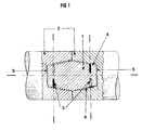
- FIG. 1 represents a longitudinal section of the joint along the plane passing through the axis of symmetry of the joint and through the axes of drilling of the blind holes acting as tanks.
- a low molecular weight phenolic resin premix is made with the hexamine catalyst in the pulverulent state (particle size 90% by weight less than 75 ⁇ m and at most 1% refusal at 150 ⁇ m) introduced progressively at a rate of 8 at 12% of the weight of resin heated to a temperature of at least 90 ° C but preferably not exceeding 110 ° C.
- the homogeneous liquid mixture once produced is cooled then poured in the form of cylindrical sticks which after solidification are placed in the tanks 3 of the nipple 1 represented in FIG. 1, and this in alternation with sticks of cement of known composition based on mixed pitch to sulfur (15 to 20% by weight).
- the reservoirs are blind holes drilled radially in the nipple along axes perpendicular to the axis of symmetry of the nipple in its frustoconical parts of smaller section so that at the time of fusion, the liquid cement can not only be distributed by gravity in the spaces which remain empty between the threads 4, but also can go back up in the free spaces or clearances 5 formed voluntarily between the nipple and the sleeves 2 and this as a result of an expansion effect following the slight evolution of gas accompanying the polymerization reaction from 130 ° C.
- the blind holes are drilled 2 to 2 opposite along the same axis, the drilling axes themselves being in the plane passing through the axis of symmetry of the joint.
- This preferred embodiment configuration can nevertheless be modified and include, for example, separate drilling axes for each hole, these drilling axes while remaining perpendicular to the axis of symmetry being able to be themselves in separate planes.
- the seal is subjected to the thermal cycle followed by the cooled electrodes and therefore it is brought up fairly quickly (1 to 2 hours) at a temperature between 150 and 250 ° C to then be maintained for several hours in this temperature range before being brought quickly again to more than 500 ° C when approaching the bath cover, then to 800 ° C or even 900 ° C at proximity to the molten charge.
Landscapes
- Physics & Mathematics (AREA)
- Engineering & Computer Science (AREA)
- Plasma & Fusion (AREA)
- Vertical, Hearth, Or Arc Furnaces (AREA)
- Resistance Heating (AREA)
- Connections Effected By Soldering, Adhesion, Or Permanent Deformation (AREA)
- Sealing Material Composition (AREA)
- Discharge Heating (AREA)
- Adhesives Or Adhesive Processes (AREA)
- Furnace Details (AREA)
- Magnetic Heads (AREA)
- Constitution Of High-Frequency Heating (AREA)
- Road Paving Structures (AREA)
- Electric Stoves And Ranges (AREA)
- Surface Heating Bodies (AREA)
- Lining Or Joining Of Plastics Or The Like (AREA)
- Gasket Seals (AREA)
- Ceramic Products (AREA)
- Electrodes For Compound Or Non-Metal Manufacture (AREA)
- Carbon And Carbon Compounds (AREA)
Claims (8)
- Dichtung zur endseitigen starren und unlösbaren Verbindung von Graphit- oder Kohleelektroden, deren Enden eine Muffe (2) mit einem Innengewinde aufweisen, in welches ein mit einem Doppelgewinde versehener Stutzen bzw. Nippel (1) mit eingebohrten Löchern geschraubt ist, die als Behälter (3) dienen für einen festen und elektrisch leitenden Zement aus einem wärmehärtbaren, verkokungsfähigen und bei Temperaturerhöhung volumenmäßig dehnbaren Werkstoff und für einen Wirkstoff, der durch Gasabgabe bei einer bestimmten Temperatur die Dehnung des Zements zwischen den Gewinden (4) des Nippels (1) und den Muffen (2) noch fördert, dadurch gekennzeichnet, daß die mindestens vier Behälter (3), welche aus Sacklöchern bestehen, die radial in den Nippel gemäß quer zu seiner Symmetrieachse verlaufenden Achsen und in seine kegelstumpfartigen Teile kleineren Querschnitts gebohrt sind, getrennt und abwechselnd mit einem Pechzement, dem ein Schaummittel beigemengt ist, und mit einem synthetischen Zement aus wärmehärtbarem Harz gefüllt sind, welcher in Präsenz eines Katalysators bei einer Temperatur von über 60°C schmilzt, um eine Flüssigphase mit einer Viskosität von weniger als 2500 Pa s zwischen 90°C und 120°C zu bilden und bei einer Temperatur von größer oder gleich 120° zu polymerisieren.
- Dichtung nach Anspruch 1, dadurch gekennzeichnet, daß der wärmehärtbare Harz des synthetischen Zements ein Phenolharz mit niedrigem Molekulargewicht und der Katalysator Hexamin bzw. Hexamethylentetramin (CH2)6N4 ist.
- Dichtung nach Anspruch 2, dadurch gekennzeichnet, daß der Massenanteil von Hexamin, das dem Phenolharz beigemengt ist, 1 bis 20 % und vorzugsweise 8 bis 12 % beträgt.
- Dichtung nach einem der Ansprüche 1 bis 3, dadurch gekennzeichnet, daß die Viskosität des synthetischen Zements zwischen 100 und 110°C vorzugsweise weniger als 500 Pa s beträgt.
- Dichtung nach einem der Ansprüche 1 bis 4, dadurch gekennzeichnet, daß die Polymerisationstemperatur des synthetischen Zements vorzugsweise in einem Bereich zwischen 120 und 140°C liegt.
- Dichtung nach einem der Ansprüche 1 bis 5, dadurch gekennzeichnet, daß der synthetische Zement einen festen Kohlenstoffgehalt mit einem Massenanteil von mehr als 55 % hat.
- Dichtung nach Anspruch 1, dadurch gekennzeichnet, daß das dem Pech beigemengte Schaummittel Schwefel mit einem Zementmassenanteil von 15 bis 20 % ist.
- Dichtung nach Anspruch 1, dadurch gekennzeichnet, daß die Behälter (3) bzw. Sacklöcher abwechselnd mit Pechzement und synthetischem Zement in Form von Stäbchen gefüllt sind.
Applications Claiming Priority (2)
| Application Number | Priority Date | Filing Date | Title |
|---|---|---|---|
| FR9207990A FR2692748B1 (fr) | 1992-06-18 | 1992-06-18 | Joint de raccordement d'electrodes de four electrique. |
| FR9207990 | 1992-06-18 |
Publications (2)
| Publication Number | Publication Date |
|---|---|
| EP0575271A1 EP0575271A1 (de) | 1993-12-22 |
| EP0575271B1 true EP0575271B1 (de) | 1997-10-08 |
Family
ID=9431315
Family Applications (1)
| Application Number | Title | Priority Date | Filing Date |
|---|---|---|---|
| EP93420249A Expired - Lifetime EP0575271B1 (de) | 1992-06-18 | 1993-06-15 | Elektrodenverbindung bei elektrischen Öfen |
Country Status (17)
| Country | Link |
|---|---|
| US (1) | US5407290A (de) |
| EP (1) | EP0575271B1 (de) |
| JP (1) | JPH0676944A (de) |
| AT (1) | ATE159140T1 (de) |
| AU (1) | AU658304B2 (de) |
| BR (1) | BR9302388A (de) |
| CA (1) | CA2098668A1 (de) |
| DE (1) | DE69314385T2 (de) |
| DK (1) | DK0575271T3 (de) |
| ES (1) | ES2107644T3 (de) |
| FI (1) | FI109171B (de) |
| FR (1) | FR2692748B1 (de) |
| GR (1) | GR3025801T3 (de) |
| MX (1) | MX9303521A (de) |
| NO (1) | NO307730B1 (de) |
| PL (1) | PL173122B1 (de) |
| TW (1) | TW226056B (de) |
Families Citing this family (7)
| Publication number | Priority date | Publication date | Assignee | Title |
|---|---|---|---|---|
| DE10253254B3 (de) * | 2002-11-15 | 2004-05-27 | Sgl Carbon Ag | Elektrodenverbindung mit beschichteten Kontaktflächen |
| FR2866513B1 (fr) * | 2004-02-13 | 2006-08-04 | Sgl Carbon | Nipple pour electrode de four a arc |
| RU2291210C1 (ru) * | 2005-05-13 | 2007-01-10 | Юрий Александрович Бурлов | Графитовый стержневой полый трубчатый электрод плазменного реактора-сепаратора |
| DE102013216452B4 (de) | 2013-08-20 | 2016-12-01 | Sgl Carbon Se | Verbesserte Elektroden/Nippel-Verbindung |
| EP3029777B1 (de) * | 2014-12-02 | 2018-09-05 | ABB Schweiz AG | Elektrische Verbindung für Mittel- und Hochspannungsschaltanlagen |
| US10108024B2 (en) | 2015-03-30 | 2018-10-23 | Panasonic Intellectual Property Management Co., Ltd. | Lens barrel |
| CN113528054A (zh) * | 2021-07-15 | 2021-10-22 | 山西贝特瑞新能源科技有限公司 | 一种锂电池坩埚用透气导电胶及其制备方法 |
Family Cites Families (12)
| Publication number | Priority date | Publication date | Assignee | Title |
|---|---|---|---|---|
| US1040830A (en) * | 1912-03-04 | 1912-10-08 | Internat Acheson Graphite Company | Sectional electrode. |
| US2810117A (en) * | 1955-07-07 | 1957-10-15 | Speer Carbon Company | Electrode connecting nipple |
| NL132919C (de) * | 1959-04-30 | 1900-01-01 | ||
| CH423029A (de) * | 1963-04-25 | 1966-10-31 | Conradty Fa C | Verfahren zur Sicherung der Schraubverbindung von Kohle- oder Graphitelektroden für elektrische Öfen gegen Lockerung |
| DE1294578B (de) * | 1963-08-16 | 1969-05-08 | Conradty Fa C | Verfahren zur Sicherung der Schraubverbindung zwischen Kohle- oder Graphitelektroden und Sicherungsformling zur Durchfuehrung des Verfahrens |
| DE3107852A1 (de) * | 1981-03-02 | 1982-09-16 | Sika AG, vorm. Kaspar Winkler & Co., 8048 Zürich | Verfahren zur herstellung von hochkonzentrierten, niedrigviskosen, waessrigen loesungen von melamin/aldehydharzen |
| US4624984A (en) * | 1984-02-24 | 1986-11-25 | Plastics Engineering Company | Moldable composition suitable for the preparation of vitreous carbon |
| US4725161A (en) * | 1986-09-05 | 1988-02-16 | Union Carbide Corporation | Electrode joint |
| DE3809361A1 (de) * | 1988-03-19 | 1989-09-28 | Sigri Gmbh | Verfahren zur verringerung des abbrands von graphitelektroden |
| US5233012A (en) * | 1989-09-01 | 1993-08-03 | Sanyo-Kokusaku Pulp Co., Ltd. | Production of novel condensates comprising bisphenols and aromatic aminosulfonic acids, condensates and dispersant, additive and water-reducing agent based thereon |
| US5033904A (en) * | 1990-01-31 | 1991-07-23 | Challis Stairways, Inc. | Tubular dowel system |
| US5130380A (en) * | 1990-05-29 | 1992-07-14 | Carew Evan B | Conductive polymers |
-
1992
- 1992-06-18 FR FR9207990A patent/FR2692748B1/fr not_active Expired - Fee Related
-
1993
- 1993-06-07 TW TW082104514A patent/TW226056B/zh active
- 1993-06-08 US US08/072,954 patent/US5407290A/en not_active Expired - Fee Related
- 1993-06-14 MX MX9303521A patent/MX9303521A/es not_active IP Right Cessation
- 1993-06-15 ES ES93420249T patent/ES2107644T3/es not_active Expired - Lifetime
- 1993-06-15 EP EP93420249A patent/EP0575271B1/de not_active Expired - Lifetime
- 1993-06-15 DK DK93420249.0T patent/DK0575271T3/da active
- 1993-06-15 AT AT93420249T patent/ATE159140T1/de not_active IP Right Cessation
- 1993-06-15 DE DE69314385T patent/DE69314385T2/de not_active Expired - Fee Related
- 1993-06-17 CA CA002098668A patent/CA2098668A1/fr not_active Abandoned
- 1993-06-17 BR BR9302388A patent/BR9302388A/pt not_active IP Right Cessation
- 1993-06-17 NO NO932244A patent/NO307730B1/no not_active IP Right Cessation
- 1993-06-17 AU AU41288/93A patent/AU658304B2/en not_active Ceased
- 1993-06-17 FI FI932795A patent/FI109171B/fi active
- 1993-06-17 PL PL93299366A patent/PL173122B1/pl unknown
- 1993-06-18 JP JP5147964A patent/JPH0676944A/ja active Pending
-
1997
- 1997-12-30 GR GR970403447T patent/GR3025801T3/el unknown
Also Published As
| Publication number | Publication date |
|---|---|
| FI109171B (fi) | 2002-05-31 |
| FR2692748B1 (fr) | 1998-07-17 |
| DE69314385D1 (de) | 1997-11-13 |
| GR3025801T3 (en) | 1998-03-31 |
| AU4128893A (en) | 1993-12-23 |
| DE69314385T2 (de) | 1998-04-16 |
| NO932244D0 (no) | 1993-06-17 |
| NO932244L (no) | 1993-12-20 |
| FI932795A0 (fi) | 1993-06-17 |
| MX9303521A (es) | 1994-01-31 |
| EP0575271A1 (de) | 1993-12-22 |
| FI932795L (fi) | 1993-12-19 |
| DK0575271T3 (da) | 1998-05-04 |
| JPH0676944A (ja) | 1994-03-18 |
| BR9302388A (pt) | 1994-01-11 |
| PL299366A1 (en) | 1993-12-27 |
| PL173122B1 (pl) | 1998-01-30 |
| US5407290A (en) | 1995-04-18 |
| ES2107644T3 (es) | 1997-12-01 |
| AU658304B2 (en) | 1995-04-06 |
| FR2692748A1 (fr) | 1993-12-24 |
| NO307730B1 (no) | 2000-05-15 |
| ATE159140T1 (de) | 1997-10-15 |
| TW226056B (de) | 1994-07-01 |
| CA2098668A1 (fr) | 1993-12-19 |
Similar Documents
| Publication | Publication Date | Title |
|---|---|---|
| EP0575271B1 (de) | Elektrodenverbindung bei elektrischen Öfen | |
| EP0214882B2 (de) | Feuerfeste Auskleidung eines metallurgischen Gefässes und Verfahren zu ihrer Herstellung | |
| BE1005914A4 (fr) | Procede et melange destine a former une masse refractaire coherente sur une surface. | |
| CA1264885A (fr) | Materiau isolant thermique, du type syntactique, a base d'elastomeres notamment, partiellement ou totalement ininflammable | |
| US2810117A (en) | Electrode connecting nipple | |
| FR2761938A1 (fr) | Frotteur en carbone a detecteur d'avaries fonctionnant sous alimentation electrique a intensite elevee | |
| JPH07111910B2 (ja) | 電極継手 | |
| FR2730227A1 (fr) | Composition pour un revetement de produits carbones et ce revetement | |
| CA1135457A (fr) | Pate carbonee pour mise en forme a froid | |
| FR2572724A1 (fr) | Piece d'usure refractaire pour couler des masses fondues liquides | |
| US2862748A (en) | Joint for carbon electrodes | |
| US4729689A (en) | Electrode member and process for the production thereof | |
| RU2107413C1 (ru) | Стыковое соединение электродов дуговой электропечи | |
| FR2657604A1 (fr) | Element faconne en ceramique refractaire et procede pour sa fabrication. | |
| EP1565040B1 (de) | Nippel für Lichtbogenelektroden | |
| WO2002068723A1 (fr) | Cathode graphite pour l'electrolyse de l'aluminium | |
| EP3464473B1 (de) | Bei raumtemperatur festes bitumen | |
| AU627945B2 (en) | Amorphous refractory material | |
| US4019019A (en) | Method of producing tube rods and articles produced therefrom | |
| US3105277A (en) | Expendable pattern bonding agent | |
| BE364466A (de) | ||
| BE357254A (de) | ||
| JPH04120184A (ja) | 炭素質成形品用接着剤 | |
| FR2781771A1 (fr) | Procede de calage d'un tube dans un logement tubulaire, notamment d'un tube lance-missile | |
| CH170374A (fr) | Produit pour le revêtement de routes et procédé pour le fabriquer. |
Legal Events
| Date | Code | Title | Description |
|---|---|---|---|
| PUAI | Public reference made under article 153(3) epc to a published international application that has entered the european phase |
Free format text: ORIGINAL CODE: 0009012 |
|
| AK | Designated contracting states |
Kind code of ref document: A1 Designated state(s): AT BE CH DE DK ES FR GB GR IE IT LI LU MC NL PT SE |
|
| 17P | Request for examination filed |
Effective date: 19940110 |
|
| 17Q | First examination report despatched |
Effective date: 19960719 |
|
| GRAG | Despatch of communication of intention to grant |
Free format text: ORIGINAL CODE: EPIDOS AGRA |
|
| GRAH | Despatch of communication of intention to grant a patent |
Free format text: ORIGINAL CODE: EPIDOS IGRA |
|
| RAP1 | Party data changed (applicant data changed or rights of an application transferred) |
Owner name: SGL CARBON S.A. |
|
| GRAH | Despatch of communication of intention to grant a patent |
Free format text: ORIGINAL CODE: EPIDOS IGRA |
|
| GRAA | (expected) grant |
Free format text: ORIGINAL CODE: 0009210 |
|
| AK | Designated contracting states |
Kind code of ref document: B1 Designated state(s): AT BE CH DE DK ES FR GB GR IE IT LI LU MC NL PT SE |
|
| PG25 | Lapsed in a contracting state [announced via postgrant information from national office to epo] |
Ref country code: AT Free format text: LAPSE BECAUSE OF FAILURE TO SUBMIT A TRANSLATION OF THE DESCRIPTION OR TO PAY THE FEE WITHIN THE PRESCRIBED TIME-LIMIT Effective date: 19971008 |
|
| REF | Corresponds to: |
Ref document number: 159140 Country of ref document: AT Date of ref document: 19971015 Kind code of ref document: T |
|
| REG | Reference to a national code |
Ref country code: CH Ref legal event code: EP |
|
| REF | Corresponds to: |
Ref document number: 69314385 Country of ref document: DE Date of ref document: 19971113 |
|
| ITF | It: translation for a ep patent filed | ||
| REG | Reference to a national code |
Ref country code: ES Ref legal event code: FG2A Ref document number: 2107644 Country of ref document: ES Kind code of ref document: T3 |
|
| GBT | Gb: translation of ep patent filed (gb section 77(6)(a)/1977) |
Effective date: 19971111 |
|
| PG25 | Lapsed in a contracting state [announced via postgrant information from national office to epo] |
Ref country code: SE Effective date: 19980108 Ref country code: PT Free format text: LAPSE BECAUSE OF FAILURE TO SUBMIT A TRANSLATION OF THE DESCRIPTION OR TO PAY THE FEE WITHIN THE PRESCRIBED TIME-LIMIT Effective date: 19980108 |
|
| REG | Reference to a national code |
Ref country code: DK Ref legal event code: T3 |
|
| PG25 | Lapsed in a contracting state [announced via postgrant information from national office to epo] |
Ref country code: IE Free format text: LAPSE BECAUSE OF NON-PAYMENT OF DUE FEES Effective date: 19980605 |
|
| PG25 | Lapsed in a contracting state [announced via postgrant information from national office to epo] |
Ref country code: LU Free format text: LAPSE BECAUSE OF NON-PAYMENT OF DUE FEES Effective date: 19980615 |
|
| PG25 | Lapsed in a contracting state [announced via postgrant information from national office to epo] |
Ref country code: LI Free format text: LAPSE BECAUSE OF NON-PAYMENT OF DUE FEES Effective date: 19980630 Ref country code: CH Free format text: LAPSE BECAUSE OF NON-PAYMENT OF DUE FEES Effective date: 19980630 |
|
| REG | Reference to a national code |
Ref country code: IE Ref legal event code: FD4D Ref document number: 76835 Country of ref document: IE |
|
| PLBE | No opposition filed within time limit |
Free format text: ORIGINAL CODE: 0009261 |
|
| STAA | Information on the status of an ep patent application or granted ep patent |
Free format text: STATUS: NO OPPOSITION FILED WITHIN TIME LIMIT |
|
| 26N | No opposition filed | ||
| PG25 | Lapsed in a contracting state [announced via postgrant information from national office to epo] |
Ref country code: MC Free format text: LAPSE BECAUSE OF NON-PAYMENT OF DUE FEES Effective date: 19981231 |
|
| REG | Reference to a national code |
Ref country code: CH Ref legal event code: PL |
|
| REG | Reference to a national code |
Ref country code: GB Ref legal event code: IF02 |
|
| PGFP | Annual fee paid to national office [announced via postgrant information from national office to epo] |
Ref country code: GB Payment date: 20030519 Year of fee payment: 11 |
|
| PGFP | Annual fee paid to national office [announced via postgrant information from national office to epo] |
Ref country code: DE Payment date: 20030521 Year of fee payment: 11 |
|
| PGFP | Annual fee paid to national office [announced via postgrant information from national office to epo] |
Ref country code: GR Payment date: 20030526 Year of fee payment: 11 |
|
| PGFP | Annual fee paid to national office [announced via postgrant information from national office to epo] |
Ref country code: DK Payment date: 20030602 Year of fee payment: 11 |
|
| PGFP | Annual fee paid to national office [announced via postgrant information from national office to epo] |
Ref country code: FR Payment date: 20030612 Year of fee payment: 11 |
|
| PGFP | Annual fee paid to national office [announced via postgrant information from national office to epo] |
Ref country code: BE Payment date: 20030616 Year of fee payment: 11 |
|
| PGFP | Annual fee paid to national office [announced via postgrant information from national office to epo] |
Ref country code: ES Payment date: 20030624 Year of fee payment: 11 |
|
| PGFP | Annual fee paid to national office [announced via postgrant information from national office to epo] |
Ref country code: NL Payment date: 20030627 Year of fee payment: 11 |
|
| PG25 | Lapsed in a contracting state [announced via postgrant information from national office to epo] |
Ref country code: GB Free format text: LAPSE BECAUSE OF NON-PAYMENT OF DUE FEES Effective date: 20040615 |
|
| PG25 | Lapsed in a contracting state [announced via postgrant information from national office to epo] |
Ref country code: ES Free format text: LAPSE BECAUSE OF NON-PAYMENT OF DUE FEES Effective date: 20040616 |
|
| PG25 | Lapsed in a contracting state [announced via postgrant information from national office to epo] |
Ref country code: DK Free format text: LAPSE BECAUSE OF NON-PAYMENT OF DUE FEES Effective date: 20040630 Ref country code: BE Free format text: LAPSE BECAUSE OF NON-PAYMENT OF DUE FEES Effective date: 20040630 |
|
| BERE | Be: lapsed |
Owner name: S.A. *SGL CARBON Effective date: 20040630 |
|
| PG25 | Lapsed in a contracting state [announced via postgrant information from national office to epo] |
Ref country code: NL Free format text: LAPSE BECAUSE OF NON-PAYMENT OF DUE FEES Effective date: 20050101 Ref country code: DE Free format text: LAPSE BECAUSE OF NON-PAYMENT OF DUE FEES Effective date: 20050101 |
|
| PG25 | Lapsed in a contracting state [announced via postgrant information from national office to epo] |
Ref country code: GR Free format text: LAPSE BECAUSE OF NON-PAYMENT OF DUE FEES Effective date: 20050105 |
|
| REG | Reference to a national code |
Ref country code: DK Ref legal event code: EBP |
|
| GBPC | Gb: european patent ceased through non-payment of renewal fee |
Effective date: 20040615 |
|
| PG25 | Lapsed in a contracting state [announced via postgrant information from national office to epo] |
Ref country code: FR Free format text: LAPSE BECAUSE OF NON-PAYMENT OF DUE FEES Effective date: 20050228 |
|
| NLV4 | Nl: lapsed or anulled due to non-payment of the annual fee |
Effective date: 20050101 |
|
| REG | Reference to a national code |
Ref country code: FR Ref legal event code: ST |
|
| PG25 | Lapsed in a contracting state [announced via postgrant information from national office to epo] |
Ref country code: IT Free format text: LAPSE BECAUSE OF NON-PAYMENT OF DUE FEES Effective date: 20050615 |
|
| REG | Reference to a national code |
Ref country code: ES Ref legal event code: FD2A Effective date: 20040616 |