EP0574539B1 - Line pressure compensator for a pressure transducer - Google Patents
Line pressure compensator for a pressure transducer Download PDFInfo
- Publication number
- EP0574539B1 EP0574539B1 EP92908775A EP92908775A EP0574539B1 EP 0574539 B1 EP0574539 B1 EP 0574539B1 EP 92908775 A EP92908775 A EP 92908775A EP 92908775 A EP92908775 A EP 92908775A EP 0574539 B1 EP0574539 B1 EP 0574539B1
- Authority
- EP
- European Patent Office
- Prior art keywords
- differential pressure
- capacitive
- static pressure
- variations
- pressure signal
- Prior art date
- Legal status (The legal status is an assumption and is not a legal conclusion. Google has not performed a legal analysis and makes no representation as to the accuracy of the status listed.)
- Expired - Lifetime
Links
Images
Classifications
-
- G—PHYSICS
- G01—MEASURING; TESTING
- G01L—MEASURING FORCE, STRESS, TORQUE, WORK, MECHANICAL POWER, MECHANICAL EFFICIENCY, OR FLUID PRESSURE
- G01L9/00—Measuring steady of quasi-steady pressure of fluid or fluent solid material by electric or magnetic pressure-sensitive elements; Transmitting or indicating the displacement of mechanical pressure-sensitive elements, used to measure the steady or quasi-steady pressure of a fluid or fluent solid material, by electric or magnetic means
- G01L9/12—Measuring steady of quasi-steady pressure of fluid or fluent solid material by electric or magnetic pressure-sensitive elements; Transmitting or indicating the displacement of mechanical pressure-sensitive elements, used to measure the steady or quasi-steady pressure of a fluid or fluent solid material, by electric or magnetic means by making use of variations in capacitance, i.e. electric circuits therefor
Definitions
- the present invention involves a differential pressure sensor. More particularly, the present invention deals with compensating a pressure sensor for changes in static pressure.
- Such sensors often include a sensor housing having an inner chamber.
- a deflectable diaphragm is inserted within the chamber dividing the chamber into two cavities.
- a first pressure is provided to the first cavity, while a second pressure is provided to the second cavity. Based on the difference in the first and second pressures, the diaphragm deflects.
- the diaphragm also typically includes a conductive portion separated from, but aligned with conductive portions on the inner walls of the cavities.
- the conductive portion on the diaphragm forms a capacitive plate.
- the conductive portions on the inner walls of the cavities also form capacitive plates. Therefore, the capacitive plate on the diaphragm forms a first variable capacitor with the capacitor plate on the interior wall of the first cavity, and a second variable capacitor with the capacitor plate on the interior wall of the second cavity.
- the pressure sensor provides an output signal representative of the ratio of capacitive values of the variable capacitors, and based on those capacitive values, the differential pressure is determined.
- Static pressure also commonly referred to as line pressure
- the first and second pressures provided to the first and second cavities of the pressure sensor may have values of, 2990 psi(P L ) and 3000 psi(P H ).
- the differential pressure is 10 psi (3000 psi - 2990 psi).
- Static pressure is sometimes defined as the average of P H and P L , or 2995 psi.
- Static pressure may also be defined simply as P H , or P L alone.
- P H or P L alone.
- Frick U.S. Patent No. 4,370,890 assigned to the assignee of the present invention discloses a mechanical configuration for a differential pressure sensor which attempts to eliminate, or compensate for, the unwanted mechanical stresses on the pressure sensor housing due to variation in static pressure. This helps to eliminate variations in the output signal of the differential pressure sensor due to variation in static pressure.
- compensation schemes which compensate for variations in the output signal due to variations in static pressure and which can be adjusted by electrical rather than mechanical means.
- DE-A-3414896 discloses a pressure difference sensor in which equal correction capacitors are connected in parallel with each of the measuring capacitors to reduce effects due to temperature drift.
- capacitive sensing means senses differential pressure and provides a differential pressure signal based on the differential pressure sensed.
- the capacitive sensing means has a capacitive value which varies with variations in static pressure, the differential pressure signal also varies with variations in static pressure.
- Capacitive compensation means has a capacitive value fixed relative to variations in static pressure, and is coupled to the capacitive sensing means. The capacitive compensation means compensates the differential pressure signal for variations due to variations in the static pressure.
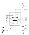
- FIG. 1 shows a portion of a differential pressure sensor in partial block diagram form.
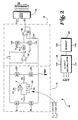
- FIG. 2 is a schematic diagram of a differential pressure sensor with one embodiment of capacitive compensation according to the present invention.
- FIG. 1 shows a differential pressure sensor 5 which includes a housing 7 having an inner chamber 9 filled with oil having a dielectric coefficient ⁇ 0 .
- the inner chamber 9 is divided into a first cavity 11 and a second cavity 13 by diaphragm 15.
- Diaphragm 15 includes a conductive portion 17 which is generally aligned with, but separated from two other conductive portions, 19 and 21, on the inner surfaces of cavities 11 and 13, respectively.
- Conductive portions 17 and 19 form two plates of a variable capacitor C 1 separated at their centers by a distant X 1 .
- Conductive portions 17 and 21 form two plates of a second variable capacitor C 2 separated at their centers by a distance X 2 .
- Two pressures, indicated by arrows P 1 and P 2 are provided by any suitable means, 23 and 25, to cavities 11 and 13.
- the means for providing pressures P 1 and P 2 to cavities 11 and 13 are preferably similar to those discussed in more detail in the Frick U.S. Patent No. 4,370,890.
- diaphragm 15 deflects within chamber 11 either toward plate 19 or toward plate 21. This deflection causes a change in the capacitive values of variable capacitors C 1 and C 2 .
- Sensor 5 provides an output signal representative of the capacitive values of the variable capacitors C 1 and C 2 and stray capacitances C S1 and C S2 . Based on the output signal, the differential pressure is determined.
- FIG. 2 shows one preferred embodiment of a charge balanced feedback transmitter using compensation according to the present invention.
- Measurement circuit 10 includes charge packet generator circuit 12, integration and comparison circuit 14, feedback circuit 16, output circuit 18 and readout circuit 20.
- Charge packet generator circuit 12 includes capacitive pressure sensor 5 which schematically shows the pair of variable capacitors C 1 and C 2 .
- Capacitors C 1 and C 2 as described above, have a capacitance value which varies as a function of differential pressure.
- Charge packet generator circuit 12 also includes linearity correction capacitors C L1 and C L2 , noise suppression resistors R1 and R2, and switches S1, S2, S3 and S4.
- Capacitors C L1 and C L2 are connected in series with one another and in parallel with capacitive sensor 5.
- Complementary drive signals ⁇ 0 and ⁇ ⁇ 0 are supplied to nodes 24 and 26, respectively.
- Node 24 is connected to center capacitor plate 17 of sensor 5, while node 26 is connected to the junction of capacitors C L1 and C L2 .
- Resistor R1 is connected at one end to capacitors C 1 and C L1 and at its opposite end to switches S1 and S4.
- resistor R2 is connected at one end to capacitors C 2 and C L2 , and at its opposite end to switches S2 and S3.
- Drive signals ⁇ ⁇ 1 , ⁇ ⁇ 2 , ⁇ ⁇ 3 and ⁇ ⁇ 4 control the conductive states of switches S1, S2, S3 and S4, respectively.
- Switches S1 and S2 are connected together to the inverting (-) input of integrator amplifier 30 in integrating and comparing circuit 14.
- Switches 53 and S4 are connected to reference potential V REF and to the non-inverting (+) input of integrator amplifier 30.
- reference voltage V REF is midway between supply voltages V DD and V SS .
- Integrating and comparing circuit 14 also includes integration capacitor C I , switches S5, S6, and S7 resistors R3 and R4, and comparator 32.
- Switches S5, S6 and S7 are controlled by signals ⁇ I , ⁇ VDD and ⁇ VSS , respectively, to form a multiplexer for supplying integrator voltage V I , supply voltage V DD , or supply voltage V SS to the inverting (-) input of comparator 32.
- Resistor R3 is connected between the output of comparator 32 and its non-inverting (+) input, and resistor R4 is connected between the non-inverting (+) input of comparator 32 and V REF to provide hysteresis.
- comparator 32 has two different threshold levels possible at its (+) input, depending upon the state of its output voltage V C .
- Output voltage V C from comparator 32 is supplied as an input to feedback circuit 16. Based upon the state of signal V C , feedback circuit 16 derives ten signals from a basic clock signal F CLK . These signals are ⁇ 0 , ⁇ ⁇ 0 , ⁇ VDDD , ⁇ VSS , ⁇ I, ⁇ ⁇ 1, ⁇ ⁇ 2 , ⁇ ⁇ 3 , ⁇ ⁇ 4 and UD.
- Feedback circuit 16 controls the charge packets supplied to integrator 30 from charge packet generator circuit 12 to achieve a charge balance over time.
- One or more charge packets of a first polarity are supplied when the ⁇ ⁇ 1 signal closes switch S1 and thus connects capacitor C 1 and C L1 through resistor R1 to the (-) input of integrator 30.
- Charge packets of opposite polarity are provided to integrator 30 when the ⁇ ⁇ 2 signal causes switch S2 to be closed.
- Output circuit 18 receives the ⁇ ⁇ 1 and ⁇ ⁇ 2 signals together with the UD signal from feedback circuit 16.
- the UD signal is indicative of whether the integrator is changing up or down.
- Output circuit 18 accumulates counts of packets of opposite polarity by counting either up or down, depending on the UD signal. Based upon the counts, output circuit 18 provides an output to readout circuit 20 which is representative of the differential pressure sensed by capacitive sensor 22 (as corrected by linearity capacitors C L1 and C L2 ).
- the timing and operation of measurement circuit 10 is described in greater detail in the Schulte et al U.S. Patent No. 4,878,012.
- C L1 and C L2 are chosen to have values sufficient to compensate for the zero and span errors caused by variation in static pressure.
- the transducer is subjected to zero static pressure and the zero and span are measured as differential pressure is varied.
- the sensor is subjected to maximum static pressure and the resulting changes or errors in zero and span are measured as differential pressure is varied from zero to full scale.
- the value of the compensation capacitors C L1 and C L2 are determined and those capacitors are placed in the circuit to compensate for the errors in differential pressure output induced by static pressure variations.
- capacitors C L1 and C L2 can also be determined to compensate for linearity errors caused by stray capacitances C S1 and C S2 . This is described more fully in the Schulte et al U.S. Patent No. 4,878,012.
- ⁇ P ⁇ transfer fcn. C 1 - C 2 - C L 1 + C L 2 C 1 + C 2 - C L 1 - C L 2
- a preferred method of implementing this transfer function is by selecting capacitors C L1 and C L2 based on line pressure errors measured with known standard values of C L1 and C L2 , then selecting new values for C L1 and C L2 that can be predicted to reduce line pressure errors to acceptable levels. After installation of these capacitors the transmitter is then compensated for output linearity errors as a function of differential pressure and output errors caused by temperature variations, preferably by well-known digital techniques.
- the shifts in the sensor with static pressure are compensated as follows.
- the output of the capacitive pressure sensor (Output) is described by the transfer function: Output ⁇ C A1 - C A2 + C S1 - C S2 - C L1 + C L2 C A1 + C A2 + C S1 + C S2 - C L1 - C L2 which is approximately proportional to ⁇ P where,
- This new zero output level will change when C 1 + C 2 decreases with static pressure (e.g., where ⁇ ( C 1 + C 2 ) ( C 1 + C 2 ) ⁇ P L ⁇ - 1%/1000 psi change in static pressure.)
- the ratio output (R) will be a function of static pressure.
- C L1 is the linearity capacitor that subtracts from and is physically connected to the variable sensor capacitor C 1 which increases with ⁇ P.
- C L1 and C L2 are chosen with a temperature coefficient substantially equal to the temperature coefficient of the dielectric constant of the oil fill. Also, C L1 and C L2 are placed very close to sensor 5 so the temperatures of C L1 and C L2 and sensor 5 are very close.
- the capacitive compensation means can take forms other than a pair of capacitor C L1 and C L2 .
- a single compensation capacitor with a varying excitation voltage and selective switching of nodes can also accomplish the compensation feature of the present invention.
Landscapes
- Physics & Mathematics (AREA)
- General Physics & Mathematics (AREA)
- Measuring Fluid Pressure (AREA)
Applications Claiming Priority (3)
| Application Number | Priority Date | Filing Date | Title |
|---|---|---|---|
| US667320 | 1991-03-08 | ||
| US07/667,320 US5163326A (en) | 1991-03-08 | 1991-03-08 | Line pressure compensator for a pressure transducer |
| PCT/US1992/001683 WO1992015850A1 (en) | 1991-03-08 | 1992-03-02 | Line pressure compensator for a pressure transducer |
Publications (3)
| Publication Number | Publication Date |
|---|---|
| EP0574539A1 EP0574539A1 (en) | 1993-12-22 |
| EP0574539A4 EP0574539A4 (show.php) | 1994-02-23 |
| EP0574539B1 true EP0574539B1 (en) | 1997-05-14 |
Family
ID=24677749
Family Applications (1)
| Application Number | Title | Priority Date | Filing Date |
|---|---|---|---|
| EP92908775A Expired - Lifetime EP0574539B1 (en) | 1991-03-08 | 1992-03-02 | Line pressure compensator for a pressure transducer |
Country Status (6)
| Country | Link |
|---|---|
| US (1) | US5163326A (show.php) |
| EP (1) | EP0574539B1 (show.php) |
| JP (1) | JP3190337B2 (show.php) |
| CA (1) | CA2101440A1 (show.php) |
| DE (1) | DE69219762T2 (show.php) |
| WO (1) | WO1992015850A1 (show.php) |
Families Citing this family (14)
| Publication number | Priority date | Publication date | Assignee | Title |
|---|---|---|---|---|
| US5237285A (en) * | 1991-10-18 | 1993-08-17 | Rosemount Inc. | Method and apparatus for capacitance temperature compensation and manufacturability in a dual plate capacitive pressure transmitter |
| JP3106805B2 (ja) | 1993-10-14 | 2000-11-06 | 富士電機株式会社 | 圧力差測定方法及び変位変換装置 |
| US5438880A (en) * | 1994-05-17 | 1995-08-08 | United Technologies Corporation | Electrostatic linear airspeed transducer |
| US5616846A (en) * | 1994-10-27 | 1997-04-01 | Kwasnik; Joseph W. | Method and apparatus for current regulation and temperature compensation |
| US6879056B2 (en) * | 2000-12-29 | 2005-04-12 | Intel Corporation | Converting sensed signals |
| DE10229703A1 (de) * | 2002-07-02 | 2004-01-15 | Endress + Hauser Gmbh + Co. Kg | Kapazitiver Drucksensor |
| JP4525222B2 (ja) * | 2004-07-21 | 2010-08-18 | 富士電機システムズ株式会社 | 静電容量式圧力測定装置 |
| CN100427911C (zh) * | 2006-11-03 | 2008-10-22 | 沈阳仪表科学研究院 | 电容差压传感器静压影响补偿方法 |
| NL2003266A1 (nl) | 2008-08-11 | 2010-02-15 | Asml Holding Nv | Multi nozzle proximity sensor employing common sensing and nozzle shaping. |
| US8234927B2 (en) * | 2010-06-08 | 2012-08-07 | Rosemount Inc. | Differential pressure sensor with line pressure measurement |
| US9038476B2 (en) * | 2012-09-27 | 2015-05-26 | Rosemount Inc. | Pressure transmitter with fill tube |
| US10309997B2 (en) * | 2013-03-15 | 2019-06-04 | Infineon Technologies Ag | Apparatus and a method for generating a sensor signal indicating information on a capacitance of a variable capacitor comprising a variable capacitance |
| US11046575B2 (en) * | 2017-10-31 | 2021-06-29 | Encite Llc | Broad range micro pressure sensor |
| CA3117915A1 (en) * | 2018-10-05 | 2020-04-09 | Avgi Engineering, Inc. | Differential pressure transmitter with intrinsic verification |
Family Cites Families (8)
| Publication number | Priority date | Publication date | Assignee | Title |
|---|---|---|---|---|
| US4091683A (en) * | 1976-09-27 | 1978-05-30 | Panex, Inc. | Single channel electrical comparative measuring system |
| US4370890A (en) * | 1980-10-06 | 1983-02-01 | Rosemount Inc. | Capacitive pressure transducer with isolated sensing diaphragm |
| US4457179A (en) * | 1981-03-16 | 1984-07-03 | The Bendix Corporation | Differential pressure measuring system |
| DE3414896A1 (de) * | 1984-04-19 | 1985-10-24 | Philips Patentverwaltung Gmbh, 2000 Hamburg | Vorrichtung zur verringerung der temperaturabhaengigkeit eines kapazitiven einkammerdifferenzdrucksensors |
| US4791352A (en) * | 1986-07-17 | 1988-12-13 | Rosemount Inc. | Transmitter with vernier measurement |
| JP2544435B2 (ja) * | 1988-04-06 | 1996-10-16 | 株式会社日立製作所 | 多機能センサ |
| US4878012A (en) * | 1988-06-10 | 1989-10-31 | Rosemount Inc. | Charge balanced feedback transmitter |
| JPH047460A (ja) * | 1990-04-24 | 1992-01-10 | Matsushita Electric Works Ltd | 床パネル |
-
1991
- 1991-03-08 US US07/667,320 patent/US5163326A/en not_active Expired - Lifetime
-
1992
- 1992-03-02 WO PCT/US1992/001683 patent/WO1992015850A1/en not_active Ceased
- 1992-03-02 JP JP50824892A patent/JP3190337B2/ja not_active Expired - Fee Related
- 1992-03-02 EP EP92908775A patent/EP0574539B1/en not_active Expired - Lifetime
- 1992-03-02 CA CA002101440A patent/CA2101440A1/en not_active Abandoned
- 1992-03-02 DE DE69219762T patent/DE69219762T2/de not_active Expired - Fee Related
Also Published As
| Publication number | Publication date |
|---|---|
| JPH06507487A (ja) | 1994-08-25 |
| EP0574539A1 (en) | 1993-12-22 |
| DE69219762T2 (de) | 1997-08-28 |
| EP0574539A4 (show.php) | 1994-02-23 |
| WO1992015850A1 (en) | 1992-09-17 |
| JP3190337B2 (ja) | 2001-07-23 |
| US5163326A (en) | 1992-11-17 |
| DE69219762D1 (de) | 1997-06-19 |
| CA2101440A1 (en) | 1992-09-09 |
Similar Documents
| Publication | Publication Date | Title |
|---|---|---|
| JP3247379B2 (ja) | 圧力トランスジューサの補正装置 | |
| EP0574539B1 (en) | Line pressure compensator for a pressure transducer | |
| EP0649010B1 (en) | Method for measuring pressure differences and device for converting displacements | |
| EP1883797B2 (en) | Line pressure measurement using differential pressure sensor | |
| JP2597042B2 (ja) | 差圧測定装置 | |
| US4977480A (en) | Variable-capacitance type sensor and variable-capacitance type sensor system using the same | |
| EP1072865B1 (en) | Sensor signal processing apparatus | |
| EP0813047A2 (en) | Transducer having redundant pressure sensors | |
| CA1239806A (en) | Capacitive sensing cell made of brittle material | |
| US5969258A (en) | Evaluation unit of a differential-pressure sensor | |
| WO1986002487A1 (en) | Circuit for capacitive sensor made of brittle material | |
| WO1989003619A1 (en) | Two-wire transmitter with threshold detection circuit | |
| CN104949794A (zh) | 针对隔膜压力传感器的跨度线压效应补偿 | |
| US6925884B2 (en) | Capacitive differential pressure sensor | |
| US5623101A (en) | Process to correct a differential pressure signal | |
| KR100196808B1 (ko) | 이중 플레이트 용량성 압력 전송기의 커패시턴스 온도 보상과 제조방법 및 장치 | |
| JPH0587665A (ja) | 差圧測定装置 | |
| JPH0439893B2 (show.php) | ||
| JPH0439894B2 (show.php) | ||
| HK1009985B (en) | Apparatus for capacitance temperature compensation and manufacturability in a dual plate capacitive pressure transmitter |
Legal Events
| Date | Code | Title | Description |
|---|---|---|---|
| PUAI | Public reference made under article 153(3) epc to a published international application that has entered the european phase |
Free format text: ORIGINAL CODE: 0009012 |
|
| 17P | Request for examination filed |
Effective date: 19930728 |
|
| AK | Designated contracting states |
Kind code of ref document: A1 Designated state(s): DE FR GB NL |
|
| A4 | Supplementary search report drawn up and despatched |
Effective date: 19940106 |
|
| AK | Designated contracting states |
Kind code of ref document: A4 Designated state(s): DE FR GB NL |
|
| 17Q | First examination report despatched |
Effective date: 19951108 |
|
| GRAG | Despatch of communication of intention to grant |
Free format text: ORIGINAL CODE: EPIDOS AGRA |
|
| GRAH | Despatch of communication of intention to grant a patent |
Free format text: ORIGINAL CODE: EPIDOS IGRA |
|
| GRAH | Despatch of communication of intention to grant a patent |
Free format text: ORIGINAL CODE: EPIDOS IGRA |
|
| GRAA | (expected) grant |
Free format text: ORIGINAL CODE: 0009210 |
|
| AK | Designated contracting states |
Kind code of ref document: B1 Designated state(s): DE FR GB NL |
|
| REF | Corresponds to: |
Ref document number: 69219762 Country of ref document: DE Date of ref document: 19970619 |
|
| ET | Fr: translation filed | ||
| PLBE | No opposition filed within time limit |
Free format text: ORIGINAL CODE: 0009261 |
|
| 26N | No opposition filed | ||
| PGFP | Annual fee paid to national office [announced via postgrant information from national office to epo] |
Ref country code: FR Payment date: 20010517 Year of fee payment: 10 |
|
| PGFP | Annual fee paid to national office [announced via postgrant information from national office to epo] |
Ref country code: NL Payment date: 20010522 Year of fee payment: 10 |
|
| REG | Reference to a national code |
Ref country code: GB Ref legal event code: IF02 |
|
| PGFP | Annual fee paid to national office [announced via postgrant information from national office to epo] |
Ref country code: GB Payment date: 20020626 Year of fee payment: 11 |
|
| PG25 | Lapsed in a contracting state [announced via postgrant information from national office to epo] |
Ref country code: NL Free format text: LAPSE BECAUSE OF NON-PAYMENT OF DUE FEES Effective date: 20021001 |
|
| PG25 | Lapsed in a contracting state [announced via postgrant information from national office to epo] |
Ref country code: FR Free format text: LAPSE BECAUSE OF NON-PAYMENT OF DUE FEES Effective date: 20021129 |
|
| NLV4 | Nl: lapsed or anulled due to non-payment of the annual fee |
Effective date: 20021001 |
|
| REG | Reference to a national code |
Ref country code: FR Ref legal event code: ST |
|
| PG25 | Lapsed in a contracting state [announced via postgrant information from national office to epo] |
Ref country code: GB Free format text: LAPSE BECAUSE OF NON-PAYMENT OF DUE FEES Effective date: 20030302 |
|
| GBPC | Gb: european patent ceased through non-payment of renewal fee | ||
| PGFP | Annual fee paid to national office [announced via postgrant information from national office to epo] |
Ref country code: DE Payment date: 20080430 Year of fee payment: 17 |
|
| PG25 | Lapsed in a contracting state [announced via postgrant information from national office to epo] |
Ref country code: DE Free format text: LAPSE BECAUSE OF NON-PAYMENT OF DUE FEES Effective date: 20091001 |