EP0573773B1 - Verfahren zur Herstellung von UV-Mikroskop - Trockenobjektiven und nach diesem Verfahren hergestellte Mikroskopobjektive - Google Patents
Verfahren zur Herstellung von UV-Mikroskop - Trockenobjektiven und nach diesem Verfahren hergestellte Mikroskopobjektive Download PDFInfo
- Publication number
- EP0573773B1 EP0573773B1 EP93107135A EP93107135A EP0573773B1 EP 0573773 B1 EP0573773 B1 EP 0573773B1 EP 93107135 A EP93107135 A EP 93107135A EP 93107135 A EP93107135 A EP 93107135A EP 0573773 B1 EP0573773 B1 EP 0573773B1
- Authority
- EP
- European Patent Office
- Prior art keywords
- millimetres
- wavelength
- sdh
- lenses
- objectives
- Prior art date
- Legal status (The legal status is an assumption and is not a legal conclusion. Google has not performed a legal analysis and makes no representation as to the accuracy of the status listed.)
- Expired - Lifetime
Links
Images

Classifications
-
- G—PHYSICS
- G02—OPTICS
- G02B—OPTICAL ELEMENTS, SYSTEMS OR APPARATUS
- G02B13/00—Optical objectives specially designed for the purposes specified below
- G02B13/14—Optical objectives specially designed for the purposes specified below for use with infrared or ultraviolet radiation
- G02B13/143—Optical objectives specially designed for the purposes specified below for use with infrared or ultraviolet radiation for use with ultraviolet radiation
-
- G—PHYSICS
- G02—OPTICS
- G02B—OPTICAL ELEMENTS, SYSTEMS OR APPARATUS
- G02B21/00—Microscopes
- G02B21/02—Objectives
Definitions
- the invention relates to a method for producing UV microscope dry objectives according to claim 1 and microscope objectives produced according to this method according to claims 2 and 3.
- DE 39 15 868 A1 discloses a UV-compatible dry lens with an aperture greater than 0.70 and an imaging scale of at least 60 x, which is corrected for the opening error for the visible spectral range and also for a selected UV wavelength.
- the correction of the spectral ranges is not fulfilled simultaneously:
- the objective consists of at least 11 lenses with at least two lens members which can be displaced relative to one another, the distance between which determines the wavelength for which the objective can be used. This distance can be adjusted on the outer lens mount, which requires a correspondingly constructed mechanical mount. A slight radial displacement that occurs during this axial movement produces an asymmetrical aberration (coma) over the entire image field. For this reason, the requirements for precision in the production of this known lens are very high.
- For the wavelength set in the UV only the opening error is corrected, but not the aberrations for a larger image field.
- the object of the invention is to create UV microscope lenses with a relatively simple optical structure in a modular system, the image defects of which for the center of the image and the image field primarily for a UV wavelength is corrected and in which an adaptation to other wavelengths can be carried out by simple measures during production.
- DUV diffraction-limited corrected imaging systems for this spectral range
- the manufacturing method according to the invention uses a type of modular system, starting from a basic lens that is primarily corrected for a single wavelength and has a certain focal length and aperture. For a number of applications of such an object, it is entirely sufficient if the actual focal length is close to the nominal focal length and the aperture is sufficiently large.
- the same resolving power as at 248 nm and an aperture of 0.70 can be achieved at a wavelength of 325 nm and an aperture of 0.90:
- the radius of the diffraction disk is 0.22 micrometers, so that in each case equally Applications in the deep sub-micrometer range are possible.
- the manufacturing method according to the invention for UV microscope objectives now uses these degrees of freedom with regard to the focal length and aperture in order to use image changes in the center of the image and the image field solely by means of changes in distance and changes in thickness, possibly only one lens within the scope of generously dimensioned thickness tolerances - for example of +/- 0.2 mm to transmit other wavelengths. Since the permissible change in thickness should only be within the scope of manufacturing tolerances, a special production of lenses with certain wavelength-specific thicknesses is not necessary; rather, the lenses with the required thicknesses can be selected as part of the production statistics and assigned to the lenses for the corresponding wavelength.
- the necessary wavelength-specific aperture is defined by the free diameter of a corresponding frame part.
- SDH (x) denotes Strehl's definition brightness for the height x (mm) in the lens, whereby SDH can have a maximum value of 1 and must be at least 0.8 for a diffraction-limited corrected optical system.
- the four lenses A, B, C, D have the following data: Fl.No. Radius (mm) Thickness / distance (mm) A B C. D 1 - 3,687 2.70 -.- -.- -.- 2nd 14,488 1.70 1.20 1.23 1.64 3rd 178,371 2.45 -.- -.- -.- 4th -10,002 2.62 2.71 2.93 2.75 5 87,083 3.10 -.- -.- -.- 6 -12,987 1.05 3.97 3.30 0.20 7 17,406 2.50 -.- -.- -.- 8th -63,274 0.60 0.21 0.63 0.10 9 9,119 2.10 -.- -.- -.- 10th 27,449 0.20 0.10 0.11 0.10 11 5,408 2.00 1.80 1.81 2.20 12th 9,824 0.15 0.10 0.11 0.17 13 2,040 2.03 -.- - -.- 14 1,714 -.
- the manufacturing method according to the invention is not limited to the lenses and their data given only by way of example, but rather can be transferred to all focal lengths / aperture combinations that are common in lenses for classical microscopy.
- the correction of the coma can be restricted to correspondingly smaller diameters and the opening error can be corrected over a larger aperture.
- an objective E with the following data is created from the objective C with 257 nm and 0.70 aperture: Fl.No. radius Thickness / distance 2nd 14,488 1.28 4th -10.002 3.02 6 -12.987 4.96 8th -63.274 0.92 10th 27,449 0.10 11 5,408 1.80 12th 9.824 0.10
Landscapes
- Physics & Mathematics (AREA)
- General Physics & Mathematics (AREA)
- Optics & Photonics (AREA)
- Health & Medical Sciences (AREA)
- Toxicology (AREA)
- Chemical & Material Sciences (AREA)
- Analytical Chemistry (AREA)
- Lenses (AREA)
Description
- Die Erfindung betrifft ein Verfahren zur Herstellung von UV - Mikroskop - Trockenobjektiven gemäß Anspruch 1 und nach diesem Verfahren hergestellte Mikroskopobjektive gemäß den Ansprüchen 2 und 3.
- Aus der DE 39 15 868 A1 ist ein UV-taugliches Trockenobjektiv mit einer Apertur größer als 0,70 und einem Abbildungsmaßstab von mindestens 60 x bekannt, das bezüglich des Öffnungsfehlers für den sichtbaren Spektralbereich und außerdem für eine ausgewählte UV - Wellenlänge korrigiert ist. Die Korrektion der Spektralbereiche ist nicht simultan erfüllt:
Das Objektiv besteht aus wenigstens 11 Linsen mit mindestens zwei gegeneinander verschiebbaren Linsengliedern,deren Abstand zueinander bestimmt, für welche Wellenlänge das Objektiv verwendet werden kann. Dieser Abstand ist an der äußeren Objektivfassung einstellbar, was eine entsprechend aufgebaute mechanische Fassung voraussetzt. Eine bei dieser axialen Bewegung auftretende, auch nur geringfügige radiale Verschiebung erzeugt einen asymmetrischen Abbildungsfehler (Koma) über das gesamte Bildfeld. Aus diesem Grund sind die Anforderungen an die Präzision bei der Herstellung dieses bekannten Objektivs sehr hoch. Für die jeweils eingestellte Wellenlänge im UV ist nur der Öffnungsfehler korrigiert, nicht jedoch die Aberrationen für ein größeres Bildfeld. - Da in vielen Fällen eine Adaptierbarkeit des Objektivs auf eine andere Wellenlänge durch den Anwender nicht erforderlich ist, liegt der Erfindung die Aufgabe zugrunde, UV - Mikroskopobjektive mit verhältnismäßig einfachem optischen Aufbau in einem Baukastensystem zu schaffen,deren Bildfehler für die Bildmitte und das Bildfeld primär für eine UV - Wellenlänge korrigiert sind und bei denen durch einfache Maßnahmen bei der Herstellung eine Adaption auf andere Wellenlängen vornehmbar ist.
- Diese Aufgabe wird erfindungsgemäß durch ein Herstellungsverfahren mit den im gekennzeichneten Teil des Anspruchs 1 angegebenen Merkmalen gelöst. Ausführungsbeispiele für danach hergestellte Mikroskopobjektive mit entsprechenden Datensätzen sind Gegenstand der Ansprüche 2 und 3.
- Durch die immer breitere verfügbarkeit und Anwendung von Excimer - Lasern und anderen im kurzwelligen UV emittierenden Lasern mit Wellenlängen zwischen 190 nm und 350 nm besteht ein zunehmender Bedarf an beugungsbegrenzt korrigierten abbildenden Systemen für diesen Spektralbereich (im folgenden DUV genannt). Da nur eine sehr geringe Zahl im DUV verwendbarer optischer Materialien existiert und zudem im DUV die Brechzahl sehr stark von der Wellenlänge abhängt, ist eine Korrektion der Farbfelder über das gesamte DUV oder auch nur ein nennenswertes Teilspektrum davon nicht möglich. Insbesondere für Wellenlängen unter 300 nm lassen sich in der Regel nur Monochromate oder Quasi-Monochromate mit einer spektralen Bandbreite von größenordnungsmäßig +/- 1nm realisieren. Beim Arbeiten mit nur einer diskreten Wellenlänge ist dies nicht notwendigerweise nachteilig. Für die Herstellung solcher Systeme bedeutet das jedoch, daß für die Vielzahl der Wellenlängen jeweils speziell optimierte Systeme entwickelt und gefertigt werden müssen. Dies bezieht sich nicht nur auf die unterschiedlichen Wellenlängen, sondern auch auf die verschiedenen Anwendungskategorien. So werden beispielsweise bei der Materialbearbeitung mit Excimer-Lasern eher Objektive mit großem freiem Arbeitsabstand und kleiner bis mittlerer Apertur notwendig sein, wohingegen für die Erzeugung kleinster Strukturen im sub-Mikrometer Bereich durch fotolithographische Prozesse oder für die Vermessung solcher Strukturen vorzugsweise Objektive mit hoher und höchster Apertur (und zwangsläufig kleinem freien Arbeitsabstand) erforderlich sind. Daraus resultiert eine Objektiv-Vielfalt mit entsprechend hohen Herstellkosten.
- Das erfindungsmäßige Herstellverfahren benutzt eine Art Baukastensystem, wobei von einem Grundobjektiv ausgegangen wird, das primär für eine einzelne Wellenlänge korrigiert ist und bei derselben eine bestimmte Brennweite sowie Apertur aufweist. Für eine Reihe von Anwendungen eines derartigen Objektves ist es dabei völlig ausreichend, wenn die tatsächliche Brennweite in der Nähe der nominellen Brennweite liegt und die Apertur hinreichend groß ist. Bei beugungsbegrenzter Abbildung ist beispielsweise bei einer Wellenlänge von 325 nm und einer Apertur von 0,90 das gleiche Auflösungsvermögen wie bei 248 nm und einer Apertur von 0,70 erzielbar: In beiden Fällen beträgt der Radius des Beugungsscheibchens 0,22 Mikrometer, sodaß gleichermaßen jeweils Anwendungen im tiefen sub-Mikrometer-Bereich möglich sind.
- Das erfindungsgemäße Herstellverfahren für UV - Mikroskopobjektive nutzt nun diese Freiheitsgrade bezüglich Brennweite und Apertur aus, um allein durch Abstandsänderungen und Dickenänderungen gegebenenfalls nur einer Linse im Rahmen großzügig bemessener Dickentoleranzen - beispielsweise von +/- 0,2 mm - die Bildfehlerkorrektion in Bildmitte und Bildfeld auf andere Wellenlängen zu übertragen. Da sich die zulässige Dickenänderung nur im Rahmen von Fertigungstoleranzen bewegen soll, ist eine spezielle Fertigung von Linsen mit bestimmten wellenlängenspezifischen Dicken nicht erforderlich; vielmehr können im Rahmen der Fertigungsstatistik die Linsen mit den erforderlichen Dicken ausgesucht und den Objektiven für die entsprechende Wellenlänge zugeordnet werden. Die notwendige wellenlängen-spezifische Apertur wird durch den freien Durchmesser eines entsprechenden Fassungsteils definiert.
- In der Zeichnung sind nach dem erfindungsgemäßen Verfahren hergestellte UV - Mikroskop - Trockenobjektive dargestellt.
- Es zeigen:
- Fig. 1a
- einen Linsenschnitt durch ein Grundobjektiv gemäß der Erfindung,
- Fig. 1b-d
- Linsenschnitte von drei Ausführungsbeispielen, die vom Grundobjektiv abgeleitet sind,
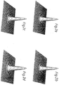
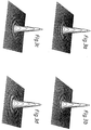
- Fig. 2a-d
- die beugungsoptischen Punktbildfunktionen der Objektive gemäß Fig. 1a-d für die Bildmitte (x=0) und
- Fig. 3a-d
- die beugungsoptischen Punktbildfunktionen der Objektive gemäß Fig. 1a-d für eine Bildhöhe x=0,05 mm.
- Nachstehend sind neben dem Grundobjektiv (A) für 325 nm drei Objektive (B,C,D) aufgeführt, die sich auf die beschriebene Art davon ableiten lassen:
Wellenlänge (nm) Brennweite (nm) Apertur SDH (0) SDH (0,05) A 325 2,50 0,90 0,997 0,907 B 248 2,35 0,70 0,992 0,972 C 257 2,39 0,70 0,990 0,979 D 355 2,49 0,80 0,997 0,963 - Darin bezeichnet SDH (x) die Strehlsche Definitionshelligkeit für die Höhe x (mm) im Objektiv, wobei SDH maximal den Wert 1 annehmen kann und für ein beugungsbegrenzt korrigiertes optisches System mindestens 0,8 betragen muß.
- Die vier Objektive A,B,C,D weisen folgende Daten auf:
Fl.Nr. Radius (mm) Dicke/Abstand (mm) A B C D 1 - 3.687 2.70 -.- -.- -.- 2 14.488 1.70 1.20 1.23 1.64 3 178.371 2.45 -.- -.- -.- 4 -10.002 2.62 2.71 2.93 2.75 5 87.083 3.10 -.- -.- -.- 6 -12.987 1.05 3.97 3.30 0.20 7 17.406 2.50 -.- -.- -.- 8 -63.274 0.60 0.21 0.63 0.10 9 9.119 2.10 -.- -.- -.- 10 27.449 0.20 0.10 0.11 0.10 11 5.408 2.00 1.80 1.81 2.20 12 9.824 0.15 0.10 0.11 0.17 13 2.040 2.03 -.- -.- -.- 14 1.714 -.- -.- -.- -.- - Das erfindungsgemäße Herstellungsverfahren ist nicht auf die nur beispielhaft angegebenen Objektive und deren Daten beschränkt, sondern auf alle bei Objektiven für die klassische Mikroskopie üblichen Brennweiten/Apertur - Kombinationen übertragbar. Mit einer Tubuslinse der Brennweite 250 mm entspricht der Objekthöhe x=0,05 mm ein Zwischenbilddurchmesser von 10 mm. Für Anwendungen, bei denen dieser relativ große Zwischenbilddurchmesser nicht notwendig ist, kann die Korrektion der Koma so auf entsprechende kleinere Durchmesser beschränkt und der Öffnungsfehler über eine größere Apertur korrigiert werden. Aus dem Objektiv C mit 257 nm und 0,70 Apertur entsteht auf diese Weise ein Objektiv E mit folgenden Daten:
Fl.Nr. Radius Dicke/Abstand 2 14,488 1,28 4 -10,002 3,02 6 -12,987 4,96 8 -63,274 0,92 10 27,449 0,10 11 5,408 1,80 12 9,824 0,10 - Für SDH (0) und SDH (0,05) erhält man hier 0,984 und 0,970.
Claims (3)
- Verfahren zur Herstellung von quasi-monochromatischen Mikroskop-Trockenobjektiven für einen Wellenlängenbereich von 190 bis 360 nm, das folgende Schritte aufweist:Entwerfen eines Grundobjektivs (A), korrigiert für Bildfehler in Bildmitte und -feld für eine bestimmte Wellenlänge in Bereich von 190 bis 360 nm;ausgehend von dem Entwurf des Grundobjektivs (A) Entwerfen einer bestimmten Anzahl von Objektiven (B,C,D) mit gleicher Linsenzahl wie das Grundobjektiv und mit im wesentlichen gleichem Auflösungsvermögen für ausgewählte Wellenlängen im Bereich von 190 bis 360 nm, wobei die Luftabstände (2,4,6,8,10,12) verändert werden;Auswählen eines der entworfenen Objektive (A,B,C,D) in Abhängigkeit von der Wellenlänge, bei der das Trockenobjektiv betrieben werden soll;Herstellen des gewählten Objektivs,
dadurch gekennzeichnet, daß beim Entwurf der bestimmten Anzahl von Objektiven (B,C,D) zusätzlich zu den Luftabständen nur noch die Linsendicke (11) verändert wird. - Verfahren nach Anspruch 1, dadurch gekennzeichnet, daß das Grundobjektiv (A) 7 Linsen (1,3,5,7,9,11,13) mit folgenden Daten aufweist:
Wellenlänge (nm): 325; Brennweite (mm): 2,50
Apertur : 0,90; SDH(o) : 0,997
SDH (0,05) : 0,907;Fl.Nr. Radius (mm) Dicke/Abstand (mm) A 1 - 3.687 2.70 2 14.488 1.70 3 178.371 2.45 4 -10.002 2.62 5 87.083 3.10 6 -12.987 1.05 7 17.406 2.50 8 -63.274 0.60 9 9.119 2.10 10 27.449 0.20 11 5.408 2.00 12 9.824 0.15 13 2.040 2.03 14 1.714 -.- - Verfahren nach Anspruch 1, dadurch gekennzeichnet, daß die vom Grundobjektiv (A) abgeleiteten Objektive (B,C,D) folgende Daten aufweisen:
B C D Wellenlänge (nm) 248 257 355 Brennweite (mm) 2,35 2,39 2,49 Apertur 0,70 0,70 0,80 SDH(0) 0,992 0,990 0,997 SDH(0,05) 0,972 0,979 0,963 Fl.Nr. Radius (mm) Dicke/Abstand (mm) B C D 1 - 3.687 -.- -.- -.- 2 14.488 1.20 1.23 1.64 3 178.371 -.- -.- -.- 4 -10.002 2.71 2.93 2.75 5 87.083 -.- -.- -.- 6 -12.987 3.97 3.30 0.20 7 17.406 -.- -.- -.- 8 -63.274 0.21 0.63 0.10 9 9.119 -.- -.- -.- 10 27.449 0.10 0.11 0.10 11 5.408 1.80 1.81 2.20 12 9.824 0.10 0.11 0.17 13 2.040 -.- -.- -.- 14 1.714 -.- -.- -.-
Applications Claiming Priority (2)
| Application Number | Priority Date | Filing Date | Title |
|---|---|---|---|
| DE4219205 | 1992-06-12 | ||
| DE4219205A DE4219205A1 (de) | 1992-06-12 | 1992-06-12 | Verfahren zur Herstellung von UV-Mikroskop - Trockenobjektiven und nach diesem Verfahren hergestellte Mikroskopobjektive |
Publications (2)
| Publication Number | Publication Date |
|---|---|
| EP0573773A1 EP0573773A1 (de) | 1993-12-15 |
| EP0573773B1 true EP0573773B1 (de) | 1996-07-31 |
Family
ID=6460837
Family Applications (1)
| Application Number | Title | Priority Date | Filing Date |
|---|---|---|---|
| EP93107135A Expired - Lifetime EP0573773B1 (de) | 1992-06-12 | 1993-05-03 | Verfahren zur Herstellung von UV-Mikroskop - Trockenobjektiven und nach diesem Verfahren hergestellte Mikroskopobjektive |
Country Status (4)
| Country | Link |
|---|---|
| US (1) | US5440422A (de) |
| EP (1) | EP0573773B1 (de) |
| JP (1) | JPH06242381A (de) |
| DE (2) | DE4219205A1 (de) |
Families Citing this family (9)
| Publication number | Priority date | Publication date | Assignee | Title |
|---|---|---|---|---|
| JPH1130754A (ja) * | 1997-07-09 | 1999-02-02 | Hamamatsu Photonics Kk | 対物レンズ |
| US5886827A (en) * | 1997-11-14 | 1999-03-23 | Nikon Corporation | Microscope objective lens with separated lens groups |
| JP2001318317A (ja) | 2000-02-29 | 2001-11-16 | Olympus Optical Co Ltd | 対物レンズ |
| US6822805B2 (en) * | 2001-07-09 | 2004-11-23 | Olympus Corporation | Objective lens |
| US20080084557A1 (en) * | 2005-11-16 | 2008-04-10 | Wei Song Tan | Optical inspection system |
| CN114442300B (zh) * | 2022-01-25 | 2023-11-24 | 复旦大学 | 一种深紫外的显微镜成像物镜 |
| JP7742790B2 (ja) | 2022-03-08 | 2025-09-22 | 京セラSoc株式会社 | 対物レンズ |
| JP7858593B2 (ja) * | 2023-05-26 | 2026-05-14 | 京セラSoc株式会社 | 対物レンズおよびそれを備えた対物レンズ装置 |
| DE102023206339A1 (de) * | 2023-07-04 | 2025-01-09 | Carl Zeiss Microscopy Gmbh | Endlich korrigiertes Mikroskop-Objektiv für Scan-Anwendungen |
Family Cites Families (10)
| Publication number | Priority date | Publication date | Assignee | Title |
|---|---|---|---|---|
| US3348896A (en) * | 1964-07-09 | 1967-10-24 | Bausch & Lomb | Modified gauss type of optical objective for use in ultraviolet light |
| US4059342A (en) * | 1975-01-28 | 1977-11-22 | Olympus Optical Co., Ltd. | Microscope objective with correcting means |
| US4050778A (en) * | 1976-08-10 | 1977-09-27 | Bell & Howell Company | Ultra-violet micrographic objective |
| JP2685179B2 (ja) * | 1987-03-27 | 1997-12-03 | 松下電器産業株式会社 | 露光装置 |
| US4770477A (en) * | 1986-12-04 | 1988-09-13 | The Perkin-Elmer Corporation | Lens usable in the ultraviolet |
| US4832472A (en) * | 1987-07-17 | 1989-05-23 | Lockheed Missiles & Space Company, Inc. | Mapping lens |
| US5121255A (en) * | 1988-06-21 | 1992-06-09 | Dainippon Screen Mfg. Co. | Objective lens system for microscope |
| DE3915868C2 (de) * | 1989-05-16 | 1996-09-12 | Zeiss Carl Fa | UV-taugliches Trockenobjektiv für Mikroskope |
| US5159492A (en) * | 1990-03-23 | 1992-10-27 | Dainippon Screen Mfg. Co., Ltd. | Objective lens system for use within microscope |
| DE69110323T2 (de) * | 1990-03-23 | 1995-10-19 | Dainippon Screen Mfg | Mikroskopobjektiv. |
-
1992
- 1992-06-12 DE DE4219205A patent/DE4219205A1/de not_active Withdrawn
-
1993
- 1993-05-03 EP EP93107135A patent/EP0573773B1/de not_active Expired - Lifetime
- 1993-05-03 DE DE59303353T patent/DE59303353D1/de not_active Expired - Lifetime
- 1993-06-04 JP JP5134702A patent/JPH06242381A/ja active Pending
- 1993-06-14 US US08/076,121 patent/US5440422A/en not_active Expired - Lifetime
Also Published As
| Publication number | Publication date |
|---|---|
| DE4219205A1 (de) | 1993-12-16 |
| US5440422A (en) | 1995-08-08 |
| EP0573773A1 (de) | 1993-12-15 |
| JPH06242381A (ja) | 1994-09-02 |
| DE59303353D1 (de) | 1996-09-05 |
Similar Documents
| Publication | Publication Date | Title |
|---|---|---|
| DE3787035T2 (de) | Optisches Projektionssystem für Präzisionskopien. | |
| EP2535752B1 (de) | Anamorphotisches Objektiv | |
| DE2828530C2 (de) | Spiegellinsenobjektiv | |
| DE102007014640B4 (de) | Mikroskopobjektiv | |
| DE19942281A1 (de) | Projektionsobjektiv | |
| EP2808716B1 (de) | Fotografisches Weitwinkelobjektiv mit Innenfokussierung | |
| DE3915868C2 (de) | UV-taugliches Trockenobjektiv für Mikroskope | |
| DE102008033341A1 (de) | Projektionsobjektiv | |
| DE3421705C2 (de) | Abtastobjektiv mit einem Hologramm | |
| DE2521528A1 (de) | Weitwinkelobjektiv | |
| EP0573773A1 (de) | Verfahren zur Herstellung von UV-Mikroskop - Trockenobjektiven und nach diesem Verfahren hergestellte Mikroskopobjektive | |
| DE3407898A1 (de) | Projektionsobjektivbaureihe | |
| DE102006052142B4 (de) | Immersions-Mikroskopobjektiv | |
| DE102006003375A1 (de) | Gruppenweise korrigiertes Objektiv | |
| DE4203464A1 (de) | Katadioptrisches reduktionsobjektiv | |
| DE112022003042T5 (de) | Optisches modul | |
| DE4106534C2 (de) | System von Teleobjektiven | |
| DE2506957C3 (de) | Mikroskopobjektiv | |
| DE102015225641A1 (de) | Zoomobjektiv | |
| DE102019121122A1 (de) | Fotografisches Objektiv | |
| EP1787154B1 (de) | Objektiv | |
| DE102008020345B4 (de) | Apochromatisches Immersionsobjektiv für Mikroskope | |
| DE102008043243A1 (de) | Projektionsobjektiv für die Mikrolithographie sowie Verfahren zum Verbessern der Abbildungseigenschaften eines Projektionsobjektivs | |
| DE10317746B4 (de) | Planapochromatisches Mikroskopobjektiv | |
| DE2915162C2 (de) | Kompaktes Weitwinkelobjektiv vom Typ umgekehrter Teleobjektive |
Legal Events
| Date | Code | Title | Description |
|---|---|---|---|
| PUAI | Public reference made under article 153(3) epc to a published international application that has entered the european phase |
Free format text: ORIGINAL CODE: 0009012 |
|
| AK | Designated contracting states |
Kind code of ref document: A1 Designated state(s): CH DE FR GB LI |
|
| 17P | Request for examination filed |
Effective date: 19931215 |
|
| 17Q | First examination report despatched |
Effective date: 19950717 |
|
| GRAH | Despatch of communication of intention to grant a patent |
Free format text: ORIGINAL CODE: EPIDOS IGRA |
|
| GRAA | (expected) grant |
Free format text: ORIGINAL CODE: 0009210 |
|
| AK | Designated contracting states |
Kind code of ref document: B1 Designated state(s): CH DE FR GB LI |
|
| GBT | Gb: translation of ep patent filed (gb section 77(6)(a)/1977) |
Effective date: 19960809 |
|
| REF | Corresponds to: |
Ref document number: 59303353 Country of ref document: DE Date of ref document: 19960905 |
|
| ET | Fr: translation filed |
Free format text: CORRECTIONS |
|
| PLBE | No opposition filed within time limit |
Free format text: ORIGINAL CODE: 0009261 |
|
| 26N | No opposition filed | ||
| REG | Reference to a national code |
Ref country code: GB Ref legal event code: IF02 |
|
| PGFP | Annual fee paid to national office [announced via postgrant information from national office to epo] |
Ref country code: CH Payment date: 20020416 Year of fee payment: 10 |
|
| PG25 | Lapsed in a contracting state [announced via postgrant information from national office to epo] |
Ref country code: LI Free format text: LAPSE BECAUSE OF NON-PAYMENT OF DUE FEES Effective date: 20030531 Ref country code: CH Free format text: LAPSE BECAUSE OF NON-PAYMENT OF DUE FEES Effective date: 20030531 |
|
| REG | Reference to a national code |
Ref country code: CH Ref legal event code: PL |
|
| PGFP | Annual fee paid to national office [announced via postgrant information from national office to epo] |
Ref country code: GB Payment date: 20040427 Year of fee payment: 12 |
|
| PGFP | Annual fee paid to national office [announced via postgrant information from national office to epo] |
Ref country code: FR Payment date: 20040512 Year of fee payment: 12 |
|
| PG25 | Lapsed in a contracting state [announced via postgrant information from national office to epo] |
Ref country code: GB Free format text: LAPSE BECAUSE OF NON-PAYMENT OF DUE FEES Effective date: 20050503 |
|
| GBPC | Gb: european patent ceased through non-payment of renewal fee |
Effective date: 20050503 |
|
| PG25 | Lapsed in a contracting state [announced via postgrant information from national office to epo] |
Ref country code: FR Free format text: LAPSE BECAUSE OF NON-PAYMENT OF DUE FEES Effective date: 20060131 |
|
| REG | Reference to a national code |
Ref country code: FR Ref legal event code: ST Effective date: 20060131 |
|
| PGFP | Annual fee paid to national office [announced via postgrant information from national office to epo] |
Ref country code: DE Payment date: 20120523 Year of fee payment: 20 |
|
| REG | Reference to a national code |
Ref country code: DE Ref legal event code: R071 Ref document number: 59303353 Country of ref document: DE |
|
| PG25 | Lapsed in a contracting state [announced via postgrant information from national office to epo] |
Ref country code: DE Free format text: LAPSE BECAUSE OF EXPIRATION OF PROTECTION Effective date: 20130504 |