EP0573684B1 - Procédé et dispositif de détection d'un paramètre fonctionnel physiologique d'un être vivant - Google Patents
Procédé et dispositif de détection d'un paramètre fonctionnel physiologique d'un être vivant Download PDFInfo
- Publication number
- EP0573684B1 EP0573684B1 EP92109688A EP92109688A EP0573684B1 EP 0573684 B1 EP0573684 B1 EP 0573684B1 EP 92109688 A EP92109688 A EP 92109688A EP 92109688 A EP92109688 A EP 92109688A EP 0573684 B1 EP0573684 B1 EP 0573684B1
- Authority
- EP
- European Patent Office
- Prior art keywords
- sampling
- counter
- frequency
- content
- measured signal
- Prior art date
- Legal status (The legal status is an assumption and is not a legal conclusion. Google has not performed a legal analysis and makes no representation as to the accuracy of the status listed.)
- Expired - Lifetime
Links
Images
Classifications
-
- A—HUMAN NECESSITIES
- A61—MEDICAL OR VETERINARY SCIENCE; HYGIENE
- A61N—ELECTROTHERAPY; MAGNETOTHERAPY; RADIATION THERAPY; ULTRASOUND THERAPY
- A61N1/00—Electrotherapy; Circuits therefor
- A61N1/18—Applying electric currents by contact electrodes
- A61N1/32—Applying electric currents by contact electrodes alternating or intermittent currents
- A61N1/36—Applying electric currents by contact electrodes alternating or intermittent currents for stimulation
- A61N1/362—Heart stimulators
- A61N1/365—Heart stimulators controlled by a physiological parameter, e.g. heart potential
- A61N1/36514—Heart stimulators controlled by a physiological parameter, e.g. heart potential controlled by a physiological quantity other than heart potential, e.g. blood pressure
- A61N1/36521—Heart stimulators controlled by a physiological parameter, e.g. heart potential controlled by a physiological quantity other than heart potential, e.g. blood pressure the parameter being derived from measurement of an electrical impedance
Definitions
- the invention relates to a method for determining a physiological functional parameter of a living being, wherein a measuring signal that changes depending on the functional parameter is detected by means of a measuring arrangement, and signal components of another parameter that also influences the measuring signal and has a characteristic frequency by filtering from the measuring signal be separated out.
- the invention further relates to a corresponding arrangement for determining the physiological function parameter.
- Such a method known from US-A-4 702 253, is used to determine the breathability of a patient.
- the blood impedance is measured with the aid of electrodes arranged in the area of the patient's heart and a measuring arrangement connected to it, which changes as a function of breathing but also as a function of the cardiac activity of the patient.
- the measurement signal is sampled in a scanning arrangement with a sampling frequency of 100 Hz and then fed to a filter arrangement in which the low-frequency signal components correlating with breathing are filtered out of the measurement signal in the range from 0.05 Hz to 1 Hz.
- the minute ventilation volume is then determined from the filtered low-frequency signal components and used for frequency control of a pacemaker.
- the low-frequency signal components correlating with respiration are filtered out by means of a bandpass filter with fixed cutoff frequencies.
- the respiratory rate can vary over a frequency range from approximately 0.09 Hz to 1.1 Hz and the heart rate in a range from approximately 0.9 Hz to 2.5 Hz varies.
- the two frequency ranges therefore overlap, so that the signal components used to determine the minute volume of breath depend not only on breathing, but also on cardiac activity, particularly at low heartbeat frequencies.
- Such a method and device is also known from US 5,025,784 and is used to determine the heart activity of a patient.
- the invention is therefore based on the object of effectively filtering out the signal portions of the other parameter from the measurement signal in a measurement signal that changes both as a function of a functional parameter to be determined and as a function of another parameter, even if the frequency of the other parameter varies.
- the object is achieved in that the period duration inversely proportional to the respective current frequency of the other parameter is continuously determined in the method of the type mentioned above and in that the mean value of the measurement signal is continuously separated from the measurement signal to separate out the signal components based on the other parameter is formed over the period of the other parameter.
- the temporal course of the mean value thus formed corresponds to a notch filtering measurement signal, the frequency range suppressed by the filtering continuously adapting to the current frequency of the signal component to be suppressed. In this way, for example, the 50/60 Hz interference signals induced by the AC network can be filtered out of an electrocardiogram.
- the other parameter consists of individual events repeating with the characteristic frequency
- the events are advantageously detected, the current period of the other parameter being determined from the time interval between the two last detected events.
- Such events are, for example, heartbeats, arm movements, pressure signals which can be filtered out of the impedance measurement signal in the case of an impedance measurement in the human body with the method according to the invention if the breathing activity of the patient is to be measured by the impedance measurement.
- the events can advantageously be detected by means of a detector device separate from the measuring arrangement.
- a detector device separate from the measuring arrangement.
- heartbeats can be detected by a heartbeat detector, e.g. QRS detector or arm movements can be detected by a motion sensor.
- signal components correlating with the events can be filtered out and evaluated for the detection of the events. Such filtering can be carried out with simple means, because only the event as such is to be detected, while the signal component associated with the event is filtered out of the measurement signal by averaging in accordance with the method according to the invention.
- the averaging is advantageously simplified in that the measurement signal is sampled at a predetermined sampling frequency and in that the mean value is formed from the sum of the sampled values acquired during the period determined for the other parameter in relation to their number. This also includes the possibility that the sampling frequency is dependent on of the determined period is changed in such a way that the number of samples remains constant with respect to the period.
- a further development of the method according to the invention provides that after the detection of an event the number of samples between this event and the previously detected sample values are newly determined and that for the following sampling times the number of sample values used in each case to form the mean value is gradually adapted to the newly determined value, starting from the value valid before the detection.
- the computational effort required for the formation of the scanning mean values can advantageously be reduced to a minimum by incrementing the counter reading of a counter at each sampling time, by transferring the counter reading to a pointer register at the first sampling time after the detection of an event and then the counter value is reset to zero, that the current sample value is read into a shift register at each point in time, the memory contents of the shift register being shifted by one memory position in the shift direction, and that for each sampling time in a computing unit the mean value from the sum of the memory contents from the first storage space as seen in the shift direction to the storage space designated by the content of the pointer register in relation to the content of the pointer register.
- the number of storage locations of the shift register is determined by the ratio of the sampling frequency to the lowest expected event frequency (e.g. heartbeat frequency), so that even at extremely low event frequencies the storage capacity of the shift register is sufficient to form the sampling values.
- the lowest expected event frequency e.g. heartbeat frequency
- the part of the above-mentioned object relating to the arrangement is advantageously achieved in that in an arrangement for determining a physiological functional parameter of a living being with a measuring arrangement in the area of the heart to form a dependence both on respiration and as a function of cardiac activity changing measuring signal, with a device connected to the measuring arrangement for sampling the measuring signal coming from the measuring arrangement with a predetermined sampling frequency and with a filter arrangement downstream of the sampling device for separating the low-frequency signal components corresponding to respiration from the measuring signal, that the arrangement has a heartbeat detector, that the filter arrangement contains a shift register into which the samples are read in succession, that an arithmetic unit is connected to the shift register, which has selective access to the memory contains the memory locations of the shift register that the heartbeat detector is connected to the reset input of a counter, the counter input of which is loaded with the sampling frequency, that a pointer register is connected to the output of the counter, which is connected to the heartbeat detector via a control input and takes over the counter reading of the counter when a heartbeat
- the arrangement according to the invention is preferably part of a pacemaker in which the mean values determined at each sampling time are used to control the pacemaker frequency.
- FIG. 1 shows the block diagram of a frequency-controlled pacemaker, from which an electrode 1 leads to the heart 2 of a patient.
- the electrode 1 is connected via a controllable switch 3 to an output connection 4 of a stimulation pulse generator 5, the second output connection 6 of which is connected to the housing of the pacemaker, not shown here.
- a heartbeat detector 7 is connected with a first input connection 8 to the output connection 4 of the stimulation pulse generator 5 and also connected with its second input connection 9 to the pacemaker housing.
- the stimulation pulse generator 5 and the heartbeat detector 7 are both connected to a pacemaker controller 10 which starts a base time interval after each stimulated or detected natural heartbeat and triggers the delivery of a stimulation pulse by the stimulation pulse generator 5 when the base time interval expires without a natural heartbeat from the heartbeat detector 7 was detected.
- a measuring arrangement 12 for measuring the impedance of the body tissue between the electrode 1 and the pacemaker housing (not shown) is also connected to the electrode 1 and the reference potential connection formed by the pacemaker housing via a further switch 11.
- the measured impedance changes both as a function of the patient's breathing and as a function of the cardiac activity.
- the stimulation pulse generator 5 with the heartbeat detector 7 and the measuring arrangement 12 can be connected separately to the electrode 1, so that they cannot influence one another.
- the analog measurement signal of the measuring arrangement 12 is Via an output line 13 to a filter arrangement 14, in which the low-frequency signal components correlating with the respiration are separated from the measurement signal and via a control line 15 to the pacemaker control 10, in which the base time interval is changed as a function of the patient's breathing.
- the stimulation of the heart 2 the detection of heartbeats and the impedance measurement take place in each case between the electrode 1 and the pacemaker housing.
- the base time interval can be controlled in addition to the breath-dependent control as a function of the higher-frequency signal components of the measurement signal that correlate with the activity of the heart.
- other physiological functional parameters of the heart such as pressure and flow, can also be recorded and used to control the pacemaker.
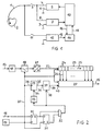
- the filter arrangement 14 is connected via a control line 16 to the pacemaker control 10, which generates a control signal on the control line 16 whenever a heartbeat is stimulated by the stimulation pulse generator 5 or a natural heartbeat has been detected by the heartbeat detector 7.
- the pacemaker control 10 which generates a control signal on the control line 16 whenever a heartbeat is stimulated by the stimulation pulse generator 5 or a natural heartbeat has been detected by the heartbeat detector 7.
- the analog measurement signal arrives via the output line 13 of the measurement arrangement 12 Low-pass or band-pass filter 17 and from there to a sampling device 18, in which the measurement signal is sampled with a predetermined sampling frequency of 10 Hz, for example, generated by a clock generator 19 and supplied to the sampling device 18 via a clock signal line 20.
- the analog sampling values are converted into corresponding digital values in an analog / digital converter 21 arranged downstream of the sampling device 18 and are read into a shift register 23 via the data signal line 22 in time with the sampling frequency, with the memory contents of the memory locations 24 of the shift register being read each time a sample value is read in again 23 can be moved in the direction of arrow 25 by one storage location 24 each.
- the number of memory locations 24 of the shift register 23 results from the ratio of the sampling frequency to the lowest expected heartbeat frequency and is therefore “20” at a sampling frequency of 10 Hz and a minimum heartbeat frequency of 30 beats per minute.
- the individual memory locations 24 are connected via output signal lines 26 to a computing unit 27 which selectively accesses the memory contents of the memory locations 24 in time with the sampling frequency and links the sample values thus obtained, as will be explained in more detail below, to an average value on the control line 15.
- the clock signal line 20 is connected to the counter input 28 of a counter 29, the counter reading of which is incremented in time with the sampling frequency, that is to say at each sampling instant.
- the control line 16 is connected to the trigger input D and the clock generator 19 to the clock input of a D flip-flop 30, which together with a downstream further D flip-flop 31 and one with the non-inverting output Q of the first D flip-flop 30 and the inverting output Q ⁇ of the second D flip-flop 31 connected AND gate 32 forms a synchronous monoflop.
- the output of the AND gate 32 is connected via a delay element 33 to a reset input 34 of the counter 29.
- the output 35 of the counter 29 is connected to the input 36 of a pointer register 37, which has a control input 38 connected to the output of the AND gate 32 and whose output 39 is connected to a control input 40 of the computing unit 27.
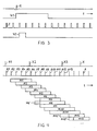
- the pacemaker controller 10 generates a control signal 41 on the control line 16 after the occurrence of a stimulated or detected heartbeat X, the length of which is at least slightly greater than the distance between two sampling times specified by the sampling clock T of the clock generator 19.
- the synchronous monoflop 30, 31, 32 generates a signal 42 at the output of the AND gate 32 at the first sampling time after the occurrence of the heartbeat X, which ends at the latest with the next sampling time.
- the signal 42 thus marks the first sampling time after a heartbeat X with its leading edge. If further heartbeats X should occur during the duration of the control signal 41, this is not registered by the synchronous monoflop 30, 31, 32.
- the duration of the control signal 41 thus corresponds to a refractory period within which incorrect detection of heartbeats for filtering the impedance signal is avoided.
- signal 42 occurs, the counter reading of counter 29 is taken over by pointer register 37 before counter 29 is reset after a short delay.
- the arithmetic unit 27 generates an average value on the control line 15 at each sampling time that is communicated to it via the clock signal line 20, which is the sum of the memory contents from the first memory location 24 seen in the shift direction 25 to the memory location designated by the content of the pointer register 37 24 divided by the content of the pointer register 37.
- FIG. 4 the occurrence of stimulated or detected heartbeats X as a function of the time t is shown in the top line.
- the sample values A are shown as they occur on the data signal power 22.
- the sampled values A naturally vary depending on the cardiac activity and the breathing activity of the patient and are marked here for the sake of simplicity by lines of the same length in each case.
- the ratio of the distances between successive heartbeats X shown in relation to the distance between two successive sampling times is also chosen arbitrarily here.
- the counter reading of the counter 29 is reset to zero and the current sampling value A1 is read into the shift register 23.
- a new sample value A2 to A5 is read into the shift register 23 and the count is incremented each time.
- the sample value A6 is read into the shift register 23 and the counter is incremented to the counter reading "5". Then the counter reading "5" is transferred to the pointer register 37 and the counter 29 is reset to zero.
- the mean is M1 marked by a bar that includes the sample values A2 to A6 taken into account when forming the mean value M1.
- a new mean value M2 is formed from the sum of the newly added sample value A7 and the earlier sample values A6 to A3 divided by the content "5" of the pointer register 37.
- the counter reading of counter 29 is incremented.
- the counter reading of the counter 29 is "6" at this point in time.
- the sample value A13 is read into the shift register 23
- the counter reading of the counter 29 is incremented to "7" and transferred to the pointer register 37, and then the counter 29 is reset to zero.
- the next mean values M9 to M13 and all further mean values are determined in a corresponding manner.
- FIG. 4 shows for the mean values M8 and M12
- larger jumps in the number of sampled values taken into account for averaging may occur in relation to the previous mean values M7 and M11.
- These jumps can be avoided by gradually adapting the number of sampled values to be taken into account from the previous value to the new value, as illustrated in FIG. 4 by the dashed bars M8 'and M9' or M12 'and M13' is. This can be done using the example of the block diagram according to FIG In this way, the count value transferred from the pointer register 37 into the computing unit 27 is compared with a count value previously stored in the computing unit 27. If the difference is less than two, the new count value is temporarily stored in the computing unit 27 instead of the previous count value.
- the previously stored count value is changed by one step or a predetermined number of steps in the direction of the new count value and then temporarily stored.
- the count value that is temporarily stored in each case is used to determine the number of samples during the summation and for the subsequent division. In this way, the number of samples to be taken into account when determining the mean value is adapted from the previous value in the pointer register 37 to the new value in the pointer register 37 at each sampling time after the occurrence of a heartbeat.
Landscapes
- Health & Medical Sciences (AREA)
- Cardiology (AREA)
- Heart & Thoracic Surgery (AREA)
- Life Sciences & Earth Sciences (AREA)
- Biomedical Technology (AREA)
- Biophysics (AREA)
- Physiology (AREA)
- Engineering & Computer Science (AREA)
- Hematology (AREA)
- Nuclear Medicine, Radiotherapy & Molecular Imaging (AREA)
- Radiology & Medical Imaging (AREA)
- Animal Behavior & Ethology (AREA)
- General Health & Medical Sciences (AREA)
- Public Health (AREA)
- Veterinary Medicine (AREA)
- Electrotherapy Devices (AREA)
- Measurement And Recording Of Electrical Phenomena And Electrical Characteristics Of The Living Body (AREA)
Claims (11)
- Procédé de détection d'un paramètre fonctionnel physiologique d'un être vivant, un signal de mesure qui varie en fonction du paramètre fonctionnel étant produit au moyen d'un dispositif de mesure (12) et des composantes de signal d'un autre paramètre influençant également le signal de mesure et possédant une fréquence caractéristique étant séparées du signal de mesure par filtrage et la durée de période inversement proportionnelle à la fréquence actuelle de l'autre paramètre étant déterminée en continu, caractérisé en ce que le signal de mesure est détecté plus d'une fois pendant une durée de période et que pour séparer du signal de mesure les composantes de signal de l'autre paramètre, on forme en continu, à chaque moment de détection, la valeur moyenne (par exemple M2) du signal de mesure sur la durée de période de l'autre paramètre.
- Procédé selon la revendication 1, caractérisé en ce que pour un autre paramètre formé d'événements (X) individuels qui se répètent avec la fréquence caractéristique, on détecte les événements (X) et que la durée de période actuelle de l'autre paramètre est déterminée à partir de l'intervalle de temps entre les deux derniers événements (par exemple X2, X1) détectés.
- Procédé selon la revendication 2, caractérisé en ce que les événements (X) sont détectés au moyen d'un dispositif de détection (7) séparé du dispositif de mesure (12).
- Procédé selon la revendication 2, caractérisé en ce qu'on sépare par filtrage du signal de mesure des composantes de signal en corrélation avec les événements (X) et qu'on les exploite pour la détection des événements (X).
- Procédé selon l'une des revendications précédentes, caractérisé en ce que le signal de mesure est lu avec une fréquence de lecture prédéterminée et que la valeur moyenne (par exemple M2) est formée à partir de la somme des valeurs de lecture (A7 à A3) détectées pendant la durée de période déterminée pour l'autre paramètre, divisée par le nombre de ces valeurs de lecture.
- Procédé selon l'une des revendications 2 à 4 et 5, caractérisé en ce qu'après la détection d'un événement (par exemple X3), on détermine de nouveau le nombre des valeurs de lecture (A) détectées entre cet événement (X3) et l'événement (X2) précédent et que pour les moments de lecture suivants, on adapte le nombre des valeurs de lecture utilisées pour former la valeur moyenne (M8', M9') progressivement à la nouvelle valeur déterminée, en partant de la valeur valable avant la détection.
- Procédé selon l'une des revendications 2 à 4 et 5, caractérisé en ce qu'à chaque moment de lecture, on incrémente la position d'un compteur (29), qu'au premier moment de lecture après la détection d'un événement (X), on transmet la position du compteur à un registre (37) pointeur puis on remet le compteur à zéro, qu'à chaque moment de lecture, la valeur de lecture actuelle est entrée dans un registre (23) à décalage, les contenus mémorisés dans le registre (23) à décalage étant décalés chaque fois d'une cellule-mémoire (24) dans le sens (25) de décalage et que pour chaque moment de lecture, on détermine dans une unité (27) de calcul la valeur moyenne en additionnant les contenus des cellules-mémoire, de la première cellule-mémoire (24) vu dans le sens (25) du décalage jusqu'à la cellule-mémoire (24) définie par le contenu du registre (37) pointeur, puis en divisant cette somme par le contenu du registre (37) pointeur.
- Procédé selon la revendication 3, caractérisé en ce qu'au premier moment de lecture suivant la détection d'un événement (X), on mémorise temporairement la position du compteur et on la compare au contenu du registre (37) pointeur et par le fait qu'aux moments de lecture suivants, on adapte le contenu du registre (37) pointeur par étapes à la position du compteur mémorisée temporairement.
- Procédé selon la revendication 7 ou 8, caractérisé en ce que le nombre des cellules-mémoire (24) du registre (23) à décalage est déterminé par le rapport de la fréquence de lecture à la fréquence d'événement minimale escomptée.
- Dispositif de détection d'un paramètre fonctionnel physiologique d'un être vivant comportant un dispositif de mesure (12) dans la région du coeur (2) pour former un signal de mesure qui varie aussi bien en fonction de la respiration qu'en fonction de l'activité cardiaque, comportant un dispositif de lecture (18) raccordé au dispositif de mesure (12) pour lire avec une fréquence de lecture prédéterminée le signal de mesure provenant du dispositif de mesure (12) et comportant un dispositif de filtrage (14) disposé en aval du dispositif de lecture (18) pour séparer par filtrage du signal de mesure les composantes de signal basse fréquence correspondant à la respiration, caractérisé en ce que le dispositif comporte un capteur (7) de battements cardiaques, que le dispositif de filtrage (14) contient un registre (23) à décalage dans lequel les valeurs de lecture sont entrées les unes après les autres, qu'il est raccordé au registre (23) à décalage une unité (27) de calcul qui a un accès sélectif aux contenus des cellules-mémoire (24) du registre (23) à décalage, que le capteur (7) de battements cardiaques est relié à l'entrée (34) de remise à zéro d'un compteur (29) dont l'entrée (28) de comptage est alimentée avec la fréquence de lecture, qu'à la sortie (35) du compteur (29) est raccordé un registre (37) pointeur qui est relié par une entrée (38) de commande au capteur (7) de battements cardiaques et auquel est transmise la position du compteur (29) lors de l'apparition d'un battement cardiaque et que l'unité (27) de calcul est reliée à la sortie (29) du registre (37) pointeur et produit à chaque moment de lecture une valeur moyenne qui résulte de l'addition des contenus des cellules-mémoire (24) du registre (23) à décalage, de la première cellule-mémoire (24), vu dans le sens (25) de décalage, à la cellule-mémoire (24) définie par le contenu du registre (37) pointeur, puis de la division de cette somme par le contenu du registre (37) pointeur.
- Dispositif selon la revendication 10, caractérisé en ce que le dispositif fait partie d'un stimulateur cardiaque dans lequel les valeurs moyennes déterminées à chaque moment de lecture sont utilisées pour commander la fréquence dudit stimulateur cardiaque.
Priority Applications (4)
| Application Number | Priority Date | Filing Date | Title |
|---|---|---|---|
| DE59209077T DE59209077D1 (de) | 1992-06-09 | 1992-06-09 | Verfahren und Vorrichtung zum Ermitteln eines physiologischen Funktionsparameters eines Lebewesens |
| EP92109688A EP0573684B1 (fr) | 1992-06-09 | 1992-06-09 | Procédé et dispositif de détection d'un paramètre fonctionnel physiologique d'un être vivant |
| US08/072,432 US5405364A (en) | 1992-06-09 | 1993-06-07 | Method and arrangement for calculating a physiological function parameter of a life form for therapy control |
| JP5137486A JPH0663160A (ja) | 1992-06-09 | 1993-06-08 | 生体の生理的な機能パラメータを求める方法および装置 |
Applications Claiming Priority (1)
| Application Number | Priority Date | Filing Date | Title |
|---|---|---|---|
| EP92109688A EP0573684B1 (fr) | 1992-06-09 | 1992-06-09 | Procédé et dispositif de détection d'un paramètre fonctionnel physiologique d'un être vivant |
Publications (2)
| Publication Number | Publication Date |
|---|---|
| EP0573684A1 EP0573684A1 (fr) | 1993-12-15 |
| EP0573684B1 true EP0573684B1 (fr) | 1997-12-17 |
Family
ID=8209692
Family Applications (1)
| Application Number | Title | Priority Date | Filing Date |
|---|---|---|---|
| EP92109688A Expired - Lifetime EP0573684B1 (fr) | 1992-06-09 | 1992-06-09 | Procédé et dispositif de détection d'un paramètre fonctionnel physiologique d'un être vivant |
Country Status (4)
| Country | Link |
|---|---|
| US (1) | US5405364A (fr) |
| EP (1) | EP0573684B1 (fr) |
| JP (1) | JPH0663160A (fr) |
| DE (1) | DE59209077D1 (fr) |
Families Citing this family (5)
| Publication number | Priority date | Publication date | Assignee | Title |
|---|---|---|---|---|
| US5531772A (en) * | 1994-11-18 | 1996-07-02 | Intermedics, Inc. | Rate responsive cardiac pacemaker with filtered impedance sensing and method |
| US6002952A (en) | 1997-04-14 | 1999-12-14 | Masimo Corporation | Signal processing apparatus and method |
| US5836976A (en) * | 1997-04-30 | 1998-11-17 | Medtronic, Inc. | Cardioversion energy reduction system |
| AU3732000A (en) * | 1999-03-12 | 2000-09-28 | Cardiac Pacemakers, Inc. | Cardiac rhythm management system with time-dependent frequency response |
| US8388670B1 (en) * | 2007-01-16 | 2013-03-05 | Pacesetter, Inc. | Sensor/lead systems for use with implantable medical devices |
Citations (1)
| Publication number | Priority date | Publication date | Assignee | Title |
|---|---|---|---|---|
| US5025784A (en) * | 1987-09-05 | 1991-06-25 | Harbin Polytechnic University | Apparatus and method for detecting and processing impedance rheogram |
Family Cites Families (22)
| Publication number | Priority date | Publication date | Assignee | Title |
|---|---|---|---|---|
| US3762397A (en) * | 1971-04-19 | 1973-10-02 | Hewlett Packard Co | Method and apparatus for the detection and recordation of high frequency sound in the cardiovascular system |
| IL39232A (en) * | 1972-04-17 | 1974-10-22 | Ben Amy Otsap | Indicator for measuring fluid quantities |
| FR2267732B1 (fr) * | 1974-04-17 | 1976-12-17 | Anvar | |
| DE2805681C2 (de) * | 1978-02-10 | 1979-11-22 | Siemens Ag, 1000 Berlin Und 8000 Muenchen | Schaltungsanordnung zur Unterdrückung von Störsignalen in einem Nutzsignal |
| NL183221C (nl) * | 1978-03-20 | 1988-09-01 | Univ Groningen | Inrichting voor het detecteren van de activiteit van de ademhalingsorganen en het hart van een levend wezen. |
| DE3107128C2 (de) * | 1981-02-26 | 1984-07-05 | Heinze, Roland, Dipl.-Ing., 8000 München | Regelschaltung zur Anpassung der Stimulationsfrequenz eines Herzschrittmachers an die Belastung eines Patienten |
| US4408615A (en) * | 1981-03-02 | 1983-10-11 | Cambridge Instruments, Inc. | Interference filter |
| US4381786A (en) * | 1981-03-02 | 1983-05-03 | Medtronic, Inc. | Tunable ECG sensing filter for pacemaker |
| US4494551A (en) * | 1982-11-12 | 1985-01-22 | Medicomp, Inc. | Alterable frequency response electrocardiographic amplifier |
| US4702253A (en) * | 1985-10-15 | 1987-10-27 | Telectronics N.V. | Metabolic-demand pacemaker and method of using the same to determine minute volume |
| DE3603673A1 (de) * | 1986-02-06 | 1987-08-13 | Strahlen Umweltforsch Gmbh | Verfahren zur elimination von stoerungen eines messsignals |
| US4730618A (en) * | 1986-06-16 | 1988-03-15 | Siemens Aktiengesellschaft | Cardiac pacer for pacing a human heart and pacing method |
| DE3774332D1 (de) * | 1986-06-16 | 1991-12-12 | Siemens Ag | Vorrichtung zur impedanzmessung an koerpergeweben. |
| US4790318A (en) * | 1986-06-16 | 1988-12-13 | Siemens Aktiengesellschaft | Cardiac pacer for pacing a human heart |
| US4899760A (en) * | 1987-06-15 | 1990-02-13 | Colin Electronics Co., Ltd. | Noise rejecting detector for biomedical signals |
| US5063927A (en) * | 1988-02-17 | 1991-11-12 | Webb Stuart C | Rate-responsive pacemaker |
| US4958640A (en) * | 1988-12-23 | 1990-09-25 | Spacelabs, Inc. | Method and apparatus for correlating the display of information contained in two information signals |
| US5105354A (en) * | 1989-01-23 | 1992-04-14 | Nippon Kayaku Kabushiki Kaisha | Method and apparatus for correlating respiration and heartbeat variability |
| US4940053A (en) * | 1989-01-25 | 1990-07-10 | Siemens-Pacesetter, Inc. | Energy controlled rate-responsive pacemaker having automatically adjustable control parameters |
| US4922930A (en) * | 1989-04-11 | 1990-05-08 | Intermedics, Inc. | Implantable device with circadian rhythm adjustment |
| US5010887A (en) * | 1989-11-17 | 1991-04-30 | Siemens-Pacesetter, Inc. | Noise discrimination in implantable pacemakers |
| US5074303A (en) * | 1990-03-08 | 1991-12-24 | Cardiac Pacemakers, Inc. | Rate adaptive cardiac pacer incorporating switched capacitor filter with cutoff frequency determined by heart rate |
-
1992
- 1992-06-09 DE DE59209077T patent/DE59209077D1/de not_active Expired - Fee Related
- 1992-06-09 EP EP92109688A patent/EP0573684B1/fr not_active Expired - Lifetime
-
1993
- 1993-06-07 US US08/072,432 patent/US5405364A/en not_active Expired - Lifetime
- 1993-06-08 JP JP5137486A patent/JPH0663160A/ja active Pending
Patent Citations (1)
| Publication number | Priority date | Publication date | Assignee | Title |
|---|---|---|---|---|
| US5025784A (en) * | 1987-09-05 | 1991-06-25 | Harbin Polytechnic University | Apparatus and method for detecting and processing impedance rheogram |
Also Published As
| Publication number | Publication date |
|---|---|
| DE59209077D1 (de) | 1998-01-29 |
| JPH0663160A (ja) | 1994-03-08 |
| US5405364A (en) | 1995-04-11 |
| EP0573684A1 (fr) | 1993-12-15 |
Similar Documents
| Publication | Publication Date | Title |
|---|---|---|
| EP0212370B1 (fr) | Surveillance de la respiration | |
| EP0000504B1 (fr) | Circuit de commutation électrique pour la détection et l'enregistrement de l'activité de la matrice | |
| DE69723400T2 (de) | System zur Anzeige von Änderungen der Körperlage | |
| DE69729960T2 (de) | Gerät zur kartierenden erfassung von körperoberflächenpotentialen | |
| DE2754333C2 (de) | Verfahren und Einrichtung zur oszillometrischen Blutdruckmessung | |
| DE19637876B4 (de) | EKG-Schrittpuls-Erfassung und -Verarbeitung | |
| EP2696924B1 (fr) | Dispositif et procédé de traitement de données de signaux physiologiques | |
| DE2905407A1 (de) | Verfahren und vorrichtung fuer das ueberwachen elektrokardiographischer wellenformen | |
| DE2716739A1 (de) | Verfahren zur detektion von signalen | |
| DE3623289A1 (de) | Blutdruckmesssystem | |
| DE2449606B2 (de) | Anordnung zur automatischen Verarbeitung von elektrischen Herzaktionssignalen | |
| DE10246404B4 (de) | Verfahren und System zur Messung von T-Wellen-Alternationen | |
| DE2515868C3 (de) | Vorrichtung zur Messung des Blutdrucks | |
| DE602004000200T2 (de) | Vorrichtung zur Analyse der Zyklus/Zyklus-Alternanz und/oder der Variabilität der ventrikulären Repolarisierungswelle eines EKG-Signals | |
| DE2722702C2 (de) | Anordnung zur Ermittlung von Änderungen des Herzschlages eines Patienten | |
| EP0584388B1 (fr) | Stimulateur cardiaque de production d'un signal correspondant au volume-par-minute d'un patient | |
| DE2344211C2 (de) | Elektromagnetischer Blut-Strömungsmesser | |
| EP0150352B1 (fr) | Procédé de détermination du point de départ et du point final d'un signal physiologique représenté par une courbe fermée | |
| DE102019006866A1 (de) | Verfahren und Vorrichtung zum Ermitteln eines respiratorischen oder eines kardiogenen Signals | |
| EP0573684B1 (fr) | Procédé et dispositif de détection d'un paramètre fonctionnel physiologique d'un être vivant | |
| DE60016261T2 (de) | Verfahren zur analyse von t-zacken mittels analytischen signalen | |
| EP1192897B1 (fr) | Contrôle de risques | |
| DE2460839C3 (de) | Meßanordnung für die Pulswellenlaufzeit einer Meßperson | |
| DE69725964T2 (de) | Herzreaktionserkennung bei Herzschrittmacher tragenden Patienten | |
| DE60302868T2 (de) | Mehrkammerstimulationssystem |
Legal Events
| Date | Code | Title | Description |
|---|---|---|---|
| PUAI | Public reference made under article 153(3) epc to a published international application that has entered the european phase |
Free format text: ORIGINAL CODE: 0009012 |
|
| AK | Designated contracting states |
Kind code of ref document: A1 Designated state(s): DE FR GB IT NL SE |
|
| 17P | Request for examination filed |
Effective date: 19940119 |
|
| RAP1 | Party data changed (applicant data changed or rights of an application transferred) |
Owner name: PACESETTER AB |
|
| 17Q | First examination report despatched |
Effective date: 19950515 |
|
| GRAG | Despatch of communication of intention to grant |
Free format text: ORIGINAL CODE: EPIDOS AGRA |
|
| GRAG | Despatch of communication of intention to grant |
Free format text: ORIGINAL CODE: EPIDOS AGRA |
|
| GRAH | Despatch of communication of intention to grant a patent |
Free format text: ORIGINAL CODE: EPIDOS IGRA |
|
| GRAH | Despatch of communication of intention to grant a patent |
Free format text: ORIGINAL CODE: EPIDOS IGRA |
|
| GRAA | (expected) grant |
Free format text: ORIGINAL CODE: 0009210 |
|
| AK | Designated contracting states |
Kind code of ref document: B1 Designated state(s): DE FR GB IT NL SE |
|
| GBT | Gb: translation of ep patent filed (gb section 77(6)(a)/1977) |
Effective date: 19971218 |
|
| REF | Corresponds to: |
Ref document number: 59209077 Country of ref document: DE Date of ref document: 19980129 |
|
| ET | Fr: translation filed | ||
| ITF | It: translation for a ep patent filed |
Owner name: STUDIO JAUMANN P. & C. S.N.C. |
|
| PG25 | Lapsed in a contracting state [announced via postgrant information from national office to epo] |
Ref country code: SE Free format text: LAPSE BECAUSE OF FAILURE TO SUBMIT A TRANSLATION OF THE DESCRIPTION OR TO PAY THE FEE WITHIN THE PRESCRIBED TIME-LIMIT Effective date: 19980317 |
|
| PGFP | Annual fee paid to national office [announced via postgrant information from national office to epo] |
Ref country code: GB Payment date: 19980515 Year of fee payment: 7 |
|
| PLBE | No opposition filed within time limit |
Free format text: ORIGINAL CODE: 0009261 |
|
| STAA | Information on the status of an ep patent application or granted ep patent |
Free format text: STATUS: NO OPPOSITION FILED WITHIN TIME LIMIT |
|
| 26N | No opposition filed | ||
| PG25 | Lapsed in a contracting state [announced via postgrant information from national office to epo] |
Ref country code: GB Free format text: LAPSE BECAUSE OF NON-PAYMENT OF DUE FEES Effective date: 19990609 |
|
| PGFP | Annual fee paid to national office [announced via postgrant information from national office to epo] |
Ref country code: NL Payment date: 19990621 Year of fee payment: 8 |
|
| GBPC | Gb: european patent ceased through non-payment of renewal fee |
Effective date: 19990609 |
|
| PG25 | Lapsed in a contracting state [announced via postgrant information from national office to epo] |
Ref country code: NL Free format text: LAPSE BECAUSE OF NON-PAYMENT OF DUE FEES Effective date: 20010101 |
|
| NLV4 | Nl: lapsed or anulled due to non-payment of the annual fee |
Effective date: 20010101 |
|
| PGFP | Annual fee paid to national office [announced via postgrant information from national office to epo] |
Ref country code: IT Payment date: 20070616 Year of fee payment: 16 |
|
| PG25 | Lapsed in a contracting state [announced via postgrant information from national office to epo] |
Ref country code: IT Free format text: LAPSE BECAUSE OF NON-PAYMENT OF DUE FEES Effective date: 20080609 |
|
| PGFP | Annual fee paid to national office [announced via postgrant information from national office to epo] |
Ref country code: FR Payment date: 20090630 Year of fee payment: 18 |
|
| PGFP | Annual fee paid to national office [announced via postgrant information from national office to epo] |
Ref country code: DE Payment date: 20090626 Year of fee payment: 18 |
|
| REG | Reference to a national code |
Ref country code: FR Ref legal event code: ST Effective date: 20110228 |
|
| PG25 | Lapsed in a contracting state [announced via postgrant information from national office to epo] |
Ref country code: DE Free format text: LAPSE BECAUSE OF NON-PAYMENT OF DUE FEES Effective date: 20110101 |
|
| PG25 | Lapsed in a contracting state [announced via postgrant information from national office to epo] |
Ref country code: FR Free format text: LAPSE BECAUSE OF NON-PAYMENT OF DUE FEES Effective date: 20100630 |