EP0573352B1 - Device for loading containers onto a carrying member - Google Patents
Device for loading containers onto a carrying member Download PDFInfo
- Publication number
- EP0573352B1 EP0573352B1 EP93401404A EP93401404A EP0573352B1 EP 0573352 B1 EP0573352 B1 EP 0573352B1 EP 93401404 A EP93401404 A EP 93401404A EP 93401404 A EP93401404 A EP 93401404A EP 0573352 B1 EP0573352 B1 EP 0573352B1
- Authority
- EP
- European Patent Office
- Prior art keywords
- conveyor
- disk
- rotation
- axis
- containers
- Prior art date
- Legal status (The legal status is an assumption and is not a legal conclusion. Google has not performed a legal analysis and makes no representation as to the accuracy of the status listed.)
- Expired - Lifetime
Links
Images


Classifications
-
- B—PERFORMING OPERATIONS; TRANSPORTING
- B65—CONVEYING; PACKING; STORING; HANDLING THIN OR FILAMENTARY MATERIAL
- B65G—TRANSPORT OR STORAGE DEVICES, e.g. CONVEYORS FOR LOADING OR TIPPING, SHOP CONVEYOR SYSTEMS OR PNEUMATIC TUBE CONVEYORS
- B65G47/00—Article or material-handling devices associated with conveyors; Methods employing such devices
- B65G47/74—Feeding, transfer, or discharging devices of particular kinds or types
- B65G47/84—Star-shaped wheels or devices having endless travelling belts or chains, the wheels or devices being equipped with article-engaging elements
- B65G47/841—Devices having endless travelling belts or chains equipped with article-engaging elements
- B65G47/842—Devices having endless travelling belts or chains equipped with article-engaging elements the article-engaging elements being grippers
-
- B—PERFORMING OPERATIONS; TRANSPORTING
- B65—CONVEYING; PACKING; STORING; HANDLING THIN OR FILAMENTARY MATERIAL
- B65G—TRANSPORT OR STORAGE DEVICES, e.g. CONVEYORS FOR LOADING OR TIPPING, SHOP CONVEYOR SYSTEMS OR PNEUMATIC TUBE CONVEYORS
- B65G47/00—Article or material-handling devices associated with conveyors; Methods employing such devices
- B65G47/74—Feeding, transfer, or discharging devices of particular kinds or types
- B65G47/84—Star-shaped wheels or devices having endless travelling belts or chains, the wheels or devices being equipped with article-engaging elements
- B65G47/846—Star-shaped wheels or wheels equipped with article-engaging elements
-
- B—PERFORMING OPERATIONS; TRANSPORTING
- B65—CONVEYING; PACKING; STORING; HANDLING THIN OR FILAMENTARY MATERIAL
- B65G—TRANSPORT OR STORAGE DEVICES, e.g. CONVEYORS FOR LOADING OR TIPPING, SHOP CONVEYOR SYSTEMS OR PNEUMATIC TUBE CONVEYORS
- B65G17/00—Conveyors having an endless traction element, e.g. a chain, transmitting movement to a continuous or substantially-continuous load-carrying surface or to a series of individual load-carriers; Endless-chain conveyors in which the chains form the load-carrying surface
- B65G17/30—Details; Auxiliary devices
- B65G17/32—Individual load-carriers
-
- B—PERFORMING OPERATIONS; TRANSPORTING
- B67—OPENING, CLOSING OR CLEANING BOTTLES, JARS OR SIMILAR CONTAINERS; LIQUID HANDLING
- B67C—CLEANING, FILLING WITH LIQUIDS OR SEMILIQUIDS, OR EMPTYING, OF BOTTLES, JARS, CANS, CASKS, BARRELS, OR SIMILAR CONTAINERS, NOT OTHERWISE PROVIDED FOR; FUNNELS
- B67C3/00—Bottling liquids or semiliquids; Filling jars or cans with liquids or semiliquids using bottling or like apparatus; Filling casks or barrels with liquids or semiliquids
- B67C3/02—Bottling liquids or semiliquids; Filling jars or cans with liquids or semiliquids using bottling or like apparatus
- B67C3/22—Details
- B67C3/24—Devices for supporting or handling bottles
- B67C3/242—Devices for supporting or handling bottles engaging with bottle necks
Definitions
- the present invention relates to improvements made to devices for loading containers having a neck, in particular bottles, on a circular or arcuate transport element in the loading area, as mentioned in the preamble of claim 1.
- transfer wheels In installations for manufacturing and / or filling containers, the movement of the containers is commonly ensured by transfer wheels, many embodiments of which are known. However, the only function provided by these wheels being a transfer function, they are not mechanically structured to withstand forces, such as vertical forces generated for example by the forced insertion of a mandrel into the neck of the containers that these wheels support.
- the transfer of the containers can be ensured by trays with notches which grip the containers and bring them under mandrels in displacement.
- the mandrels move rectilinearly: the transfer of the containers must therefore be carried out in the rectilinear travel zone of the mandrels and this results in a large footprint of the installation.
- Document US-A-3,863,753 describes a container loading device in which the containers are supported, by their bottom, by respective trays vertically movable to bring the containers to the level of gripping means arranged to enclose the necks of the containers.
- the fact that the containers are supported by their bottom implies that the distance between the support plate and the gripping means is predetermined for a given dimension of the container, and the treatment of containers of different sizes require, each time, an adjustment of the device.
- the vertical movement of the containers to bring them to the level of the gripping means leads to an increased vertical dimension, and therefore to a significant bulk of the device.
- the external gripping of the necks risks causing damage to the external wall of the necks, and in particular the screw threads intended for the caps, making it impossible to screw the caps properly; and it is not possible to avoid this drawback by using internal gripping means forced into the necks because the driving force would irreparably deform the wall of the body of the containers which is thin and therefore fragile .
- the object of the invention is essentially to improve the loading devices by eliminating the drawbacks presented by the prior devices and, as such, to propose an improved loading device which is mechanically structured to withstand vertical forces exerted on the containers taken under load and which is produced in a compact configuration making it less bulky than certain known devices.
- a loading device of the type mentioned in the preamble, being arranged in accordance with the invention is essentially characterized as indicated in the characterizing part of claim 1.
- the collection plate which grasps the containers on arrival and presents them to the transport element and the transport element itself, at least in the part of its trajectory coincidentally with the collection plate, there are superimposed rotating structures and the step of loading the containers from the collection plate on the transport element is carried out in a curved (circular) trajectory part: this results in a reduction of the longitudinal extent of the installation equipped with said loading device.
- the transport element can be mechanically structured as strongly as desired, in particular to withstand vertical forces such as those generated for example by the forced insertion of a mandrel into the neck of each container.
- the plate is arranged in such a way that its means for receiving the containers follow a circular trajectory having the above-mentioned predetermined diameter and the axis of rotation of the plate is spaced from the axis of rotation of the transport element. so as to create the aforesaid intersection of the respective trajectories of the gripping members and of the reception means. Correct operation of the device is obtained when the angle of intersection of the respective trajectories of the means for receiving the plate and the gripping members of the transport element is approximately 2 to 5 °, preferably 3 °.
- the axis of rotation of the plate is offset with respect to the axis of rotation of the transport element so that beyond (in the direction of rotation) the intersection of the trajectories of receiving means and gripping members, the means for receiving the plate move away from the gripping members of the transport element towards the interior of the trajectory in an arc followed by the latter, so that the receiving means discharged from their respective containers no longer interfere with said containers supported by the gripping members, as has been suggested above.
- the transport element comprises an endless transport chain equipped with said gripping members and a support and drive wheel for said endless chain rotating around said axis of rotation, the aforesaid members gripping carried by the endless chain describing said trajectory in an arc of a diameter predetermined when the chain passes over said wheel; in this case, the vertical rotating shaft supports the drive wheel of the endless chain.
- the loading device shown in figs. 1 and 2 essentially comprises a turntable 1 for collecting the containers, which are brought to it tangentially (for example according to arrow 2) by any supply means known to those skilled in the art (for example worm system apprehending the containers by their body), and a transport element 3 equipped with organs 4 for individual gripping of the containers presented to it by the tray 1; the transport element 3 is located above the collection plate 1 and both rotate in the same direction.
- the receptacles have a neck (they are for example bottles or the like) and they are brought (according to arrow 2) one after the other along the axis 7 trajectory while being separated from each other by a predetermined pitch P by pitching means (not shown).
- the collection plate 1 which rotates about an axis 6, has, along its peripheral edge 8, means for receiving the necks of the containers constituted by a series of mutually spaced notches 5 circumferentially by a step also having the aforementioned value P. These notches are suitable for receiving the necks of the containers and for supporting the said containers by means of a projecting annular flange surrounding the necks and bearing on the edge of the notches.
- the transport element 3 essentially consists of an articulated structure closed on itself and forming an endless chain 9 with mutually pivoting links, each of which is arranged to support a container by its neck.
- Said transport element further comprises a drive wheel 10 of relatively large diameter on which the endless chain 9 is wound and which is arranged to support and drive the latter, as well as motor means ensuring the synchronous drive of the pitching means 7 and of the drive wheel 10 which rotates about an axis 11.
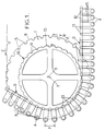
- the transport chain 9 As for the transport chain 9, it consists of a succession of links 12 articulated to freely rotate with each other by pivots 13 of large diameter which are capable of fitting into radial notches 14 provided for the periphery of the wheel 10, which thus provides support and drive for the chain 9.
- Each link 12 is provided with a transverse arm 15 directed radially outwards (considered when the chain is wound on the wheel 10 ).
- Each arm is provided at its free end with a member 4 for gripping a container by its neck.
- FIG. 3 shows an exemplary embodiment of a gripping member 4 capable of being used in the context of the present invention, in particular, but not exclusively, by being mounted at the ends of the arms 15 of the transport chain 9.
- Each member grip 4 comprises a vertical mandrel 16 movable in a sheath 17 supported for free rotation by the arm 15.
- the upper end of a rod 18 extending the mandrel 16 through the sheath 17 and projecting towards the top beyond the latter is provided with rollers 19 able to cooperate with fixed side cams (not shown) for raising and lowering (double arrow 20) sequentially the mandrel 16.
- Each mandrel 16 has a calibrated outside diameter corresponding or slightly smaller than the inside diameter of the container neck.
- the mandrel 16 For gripping (or “vetissage”) of a container by its neck, the mandrel 16 is forced into the neck of the container until an annular stop 21, surrounding the mandrel 16 and carried by the end lower of the sheath 17, comes into contact with the edge of the neck. Thus depressed, the mandrel is able to support the container.
- the circular path followed by the receiving means provided on the collection plate and the circular path or in an arc followed by the axis of the gripping members supported by the transport element have the same radius. Therefore, in the embodiment more particularly described above, the diameter of the toothed wheel 10, the length of the links 12 and the length of the arms 15 are determined in such a way that, as soon as the chain is wound on the wheel 10, the ends of the radiating arms 15 move away from each other with an inter-axis of value P corresponding to the inter-axis with which the underlying containers are brought by the collecting plate 1.
- the axis 11 of the drive wheel 10 is offset relative to the axis 6 of the collection plate 1 so that the aforementioned circular or arcuate paths intersect (in vertical projection) under a angle ⁇ between 2 and 5 °, preferably about 3 °, at a geographically fixed point A.
- the rotation drive of the wheel 10 and the rotation drive of the plate 1 are synchronized in such a way that a gripping member 4 and a notch 5 of the collection plate are present in synchronism, at point A, directly above each other; moreover, the cams (not shown) control at this precise point the descent of the mandrel 16 previously reassembled in the erased position (double arrow 20 in FIG. 3) and its fitting into the neck of the underlying container.
- the axis of rotation 6 of the plate 1 it is desirable for the axis of rotation 6 of the plate 1 to be offset with respect to the axis of rotation 11 of the drive wheel 10 in such a way that beyond point A d intersection of the trajectories of the means for receiving the tray and the gripping members of the means of transport, the edge 8 of the tray 1 and the means for receiving the necks which are provided therein deviate from the gripping members towards the inside of the trajectory in an arc followed by the latter, so that the receiving means unloaded from their respective containers no longer interfere with said containers supported by the gripping members.
- the wheel 10 and the plate 1 are driven from the same single motor member by implementing the arrangement transmission shown in Figure 2.
- the drive wheel 10 of the endless chain 9 is supported at the upper end of a substantially vertical shaft 22 (and materializing the axis of rotation of said wheel) of which it is integral in rotation.
- This shaft is itself supported on the frame 23 of the machine by a fixed support 24 which will be discussed below, support that it crosses freely, and the lower end of the shaft 22 is secured to drive motor means 25.
- the fixed support or yoke 24 has a frustoconical external shape and it will be noted above all that it is not coaxial with the shaft 22, but that its axis is eccentric relative to the latter.
- the hub 26 of complementary shape of the collection plate 1 which, taking into account this arrangement, is located under the wheel 10 and rotates around the axis of the frustoconical support (which is the aforementioned axis of rotation 6) offset from the axis 11 of the wheel 10.
- the rotational drive of the collecting plate 1 is carried out, from the motor shaft 22, by a first wheel 27 wedged thereon which, using a belt 28 drives a second wheel 29 d parallel axis wedged on one end of an intermediate shaft 30 supported by the frame 3.
- a third wheel 31 On the other end of the shaft 30 is wedged a third wheel 31 which, by a belt 32, drives a fourth wheel 33 with an axle 6 and secured to the hub 26 of the collection plate 1.
- the transmission ratios of the assembly 27, 28, 29 and of the assembly 31, 32, 33 being such that the gripping members 4 and the receiving means 5 of the plate are respectively presented successively in synchronism at point A.
- the transport element which, in the example previously described and shown in Figures 1 and 2, is constituted in the form of an endless chain supported by a drive wheel may be in the form of a simple transport wheel having the required diameter: whatever the embodiment adopted, it suffices that the gripping members follow, in the loading area, a trajectory in an arc of a circle of the same radius as the plate, centered on an axis offset from the axis of rotation of said plate.
- the gripping members can be formed in any other form than that taken as an example and shown in FIG. 3.
Description
La présente invention concerne des perfectionnements apportés aux dispositifs de chargement de récipients présentant un goulot, notamment de bouteilles, sur un élément de transport circulaire ou en arc de cercle dans la zone de chargement, tel que mentionné dans le préambule de la revendication 1.The present invention relates to improvements made to devices for loading containers having a neck, in particular bottles, on a circular or arcuate transport element in the loading area, as mentioned in the preamble of claim 1.
Dans les installations de fabrication et/ou de remplissage de récipients, le déplacement des récipients est couramment assuré par des roues de transfert dont de nombreuses réalisations sont connues. Toutefois, la seule fonction assurée par ces roues étant une fonction de transfert, elles ne sont pas mécaniquement structurées pour supporter des efforts, tels que des efforts verticaux engendrés par exemple par l'enfoncement à force d'un mandrin dans le goulot des récipients que ces roues supportent.In installations for manufacturing and / or filling containers, the movement of the containers is commonly ensured by transfer wheels, many embodiments of which are known. However, the only function provided by these wheels being a transfer function, they are not mechanically structured to withstand forces, such as vertical forces generated for example by the forced insertion of a mandrel into the neck of the containers that these wheels support.
Par ailleurs, dans les fours de chauffage de la matière plastique constitutive des récipients, qui sont utilisés dans les installations de fabrication des récipients, le transfert des récipients peut être assuré par des plateaux à encoches qui saisissent les récipients et les amènent sous des mandrins en déplacement. Toutefois, dans ces installations connues, les mandrins se déplacent rectilinéairement : le transfert des récipients doit donc s'effectuer dans la zone de parcours rectilinéaire des mandrins et il en résulte un grand encombrement de l'installation.Furthermore, in the furnaces for heating the plastic material of the containers, which are used in the installations for manufacturing the containers, the transfer of the containers can be ensured by trays with notches which grip the containers and bring them under mandrels in displacement. However, in these known installations, the mandrels move rectilinearly: the transfer of the containers must therefore be carried out in the rectilinear travel zone of the mandrels and this results in a large footprint of the installation.
Le document US-A-3 863 753 décrit un dispositif de chargement de récipients dans lequel les récipients sont soutenus, par leur fond, par des plateaux respectifs déplaçables verticalement pour amener les récipients au niveau de moyens de préhension agencés pour enserrer extérieurement les cols des récipients. Le fait que les récipients soient soutenus par leur fond implique que la distance entre le plateau de support et les moyens de préhension est prédéterminée pour une dimension donnée du récipient, et le traitement de récipients de tailles différentes nécessitent, à chaque fois, un réglage du dispositif. En outre, le déplacement vertical des récipients pour les amener au niveau des moyens de préhension conduit à une dimension verticale accrue, et donc à un encombrement important du dispositif. Enfin, la saisie extérieure des cols, par les moyens de préhension risque d'entraîner un endommagement de la paroi extérieure des cols, et notamment des filets de vissage destinés aux bouchons, rendant impossible un vissage correct des bouchons ; et il n'est pas possible d'écarter cet inconvénient en ayant recours à des moyens de préhension intérieure enfoncés à force dans les goulots car l'effort d'enfoncement risquerait de déformer irrémédiablement la paroi des corps des récipients qui est mince et donc fragile.Document US-A-3,863,753 describes a container loading device in which the containers are supported, by their bottom, by respective trays vertically movable to bring the containers to the level of gripping means arranged to enclose the necks of the containers. The fact that the containers are supported by their bottom implies that the distance between the support plate and the gripping means is predetermined for a given dimension of the container, and the treatment of containers of different sizes require, each time, an adjustment of the device. In addition, the vertical movement of the containers to bring them to the level of the gripping means leads to an increased vertical dimension, and therefore to a significant bulk of the device. Finally, the external gripping of the necks, by the gripping means risks causing damage to the external wall of the necks, and in particular the screw threads intended for the caps, making it impossible to screw the caps properly; and it is not possible to avoid this drawback by using internal gripping means forced into the necks because the driving force would irreparably deform the wall of the body of the containers which is thin and therefore fragile .
L'invention a essentiellement pour but d'améliorer les dispositifs de chargement en écartant les inconvénients présentés par les dispositifs antérieurs et, à ce titre, de proposer un dispositif de chargement perfectionné qui soit structuré mécaniquement pour supporter des efforts verticaux exercés sur les récipients pris en charge et qui soit réalisé dans une configuration compacte le rendant moins encombrant que certains dispositifs connus.The object of the invention is essentially to improve the loading devices by eliminating the drawbacks presented by the prior devices and, as such, to propose an improved loading device which is mechanically structured to withstand vertical forces exerted on the containers taken under load and which is produced in a compact configuration making it less bulky than certain known devices.
A ces fins, un dispositif de chargement du type cité au préambule, étant agencé conformément à l'invention, se caractérise essentiellement comme indiqué dans la partie caractérisante de la revendication 1.For these purposes, a loading device of the type mentioned in the preamble, being arranged in accordance with the invention, is essentially characterized as indicated in the characterizing part of claim 1.
Ainsi grâce aux dispositions conformes à l'invention, le plateau de recueil qui saisit les récipients à leur arrivée et les présente à l'élément de transport et l'élément de transport lui-même, au moins dans la partie de sa trajectoire en coïncidence avec le plateau de recueil, sont des structures tournantes superposées et l'étape de chargement des récipients depuis le plateau de recueil sur l'élément de transport s'effectue dans une partie de trajectoire en courbe (circulaire) : il en résulte une réduction de l'étendue longitudinale de l'installation équipée dudit dispositif de chargement.Thus, thanks to the arrangements in accordance with the invention, the collection plate which grasps the containers on arrival and presents them to the transport element and the transport element itself, at least in the part of its trajectory coincidentally with the collection plate, there are superimposed rotating structures and the step of loading the containers from the collection plate on the transport element is carried out in a curved (circular) trajectory part: this results in a reduction of the longitudinal extent of the installation equipped with said loading device.
De plus, l'étendue de ladite partie de trajectoire en courbe nécessaire au chargement étant relativement faible, on peut utiliser une portion subséquente de la trajectoire circulaire des récipients pris en charge par l'élément de transport -circulaire ou en arc de cercle- pour traiter ou commencer à traiter les récipients dans cette zone courbe. Il en résulte, là encore, une économie sur l'encombrement général de l'installation.In addition, the extent of said part of the curved trajectory necessary for loading being relatively small, it is possible to use a subsequent portion of the circular trajectory of the containers supported by the transport element - circular or in an arc of a circle - for treat or start to treat containers in this curved area. This again results in savings on the overall size of the installation.
En outre, l'élément de transport peut être mécaniquement structuré de façon aussi résistante que souhaité, en particulier pour supporter des efforts verticaux tels que ceux engendrés par exemple par l'enfoncement à force d'un mandrin dans le goulot de chaque récipient.In addition, the transport element can be mechanically structured as strongly as desired, in particular to withstand vertical forces such as those generated for example by the forced insertion of a mandrel into the neck of each container.
Enfin, le fait que les récipients amenés par le plateau de recueil et les organes de préhension équipant l'élément de transport suivent des trajectoires circulaires sécantes, et non pas tangentes (tangence intérieure), réunit deux avantages :
- sur le plan géométrique, la coïncidence verticale de chaque organe de préhension et de chaque récipient est beaucoup mieux définie que dans le cas de trajectoires tangentes ;
- sur le plan mécanique, la coïncidence verticale peut être assurée de façon plus aisée et plus fiable dans le temps, tandis que des jeux inévitables apparaissant avec le temps rendraient plus aléatoire et moins fiable une coïncidence par trajectoires tangentes ; en outre des trajectoires sécantes permettent un dégagement plus rapide du plateau une fois le récipient pris en charge par l'élément de transport et évitent une interférence de pièces en mouvement dans certaines configurations de montage et d'emploi du dispositif de chargement.
- on the geometric level, the vertical coincidence of each gripping member and of each container is much better defined than in the case of tangent trajectories;
- mechanically, the vertical coincidence can be more easily and more reliably ensured over time, while inevitable games appearing over time would make coincidence by tangent trajectories more random and less reliable; in addition intersecting paths allow faster release of the tray once the container is supported by the transport element and avoid interference of moving parts in certain mounting and use configurations of the loading device.
De façon préférentielle, le plateau est agencé de manière telle que ses moyens de réception des récipients suivent une trajectoire circulaire ayant le susdit diamètre prédéterminé et l'axe de rotation du plateau est écarté de l'axe de rotation de l'élément de transport de façon à créer la susdite intersection des trajectoires respectives des organes de préhension et des moyens de réception. Un fonctionnement correct du dispositif est obtenu lorsque l'angle d'intersection des trajectoires respectives des moyens de réception du plateau et des organes de préhension de l'élément de transport est d'environ 2 à 5°, de préférence 3°.Preferably, the plate is arranged in such a way that its means for receiving the containers follow a circular trajectory having the above-mentioned predetermined diameter and the axis of rotation of the plate is spaced from the axis of rotation of the transport element. so as to create the aforesaid intersection of the respective trajectories of the gripping members and of the reception means. Correct operation of the device is obtained when the angle of intersection of the respective trajectories of the means for receiving the plate and the gripping members of the transport element is approximately 2 to 5 °, preferably 3 °.
De façon avantageuse, l'axe de rotation du plateau est décalé par rapport à l'axe de rotation de l'élément de transport de manière qu'au delà (dans le sens de rotation) de l'intersection des trajectoires de moyens de réception et des organes de préhension, les moyens de réception du plateau s'écartent des organes de préhension de l'élément de transport vers l'intérieur de la trajectoire en arc de cercle suivie par ces derniers, de façon que les moyens de réception déchargés de leurs récipients respectifs n'interfèrent plus avec lesdits récipients pris en charge par les organes de préhension, comme cela a été suggéré plus haut.Advantageously, the axis of rotation of the plate is offset with respect to the axis of rotation of the transport element so that beyond (in the direction of rotation) the intersection of the trajectories of receiving means and gripping members, the means for receiving the plate move away from the gripping members of the transport element towards the interior of the trajectory in an arc followed by the latter, so that the receiving means discharged from their respective containers no longer interfere with said containers supported by the gripping members, as has been suggested above.
Dans un mode de réalisation préféré, le dispositif comporte :
- un arbre tournant vertical supportant l'élément de transport,
- une chape fixe de révolution traversée à libre rotation par ledit arbre et excentrée par rapport audit arbre, et
- un moyeu tournant monté à libre rotation autour de ladite chape, ce moyeu étant solidaire du plateau qui s'étend en-dessous de l'élément de transport.
- a vertical rotating shaft supporting the element of transport,
- a fixed yoke of revolution traversed by free rotation by said shaft and eccentric with respect to said shaft, and
- a rotating hub mounted for free rotation around said yoke, this hub being integral with the plate which extends below the transport element.
Dans ce cas, il est avantageux de simplifier la conception du dispositif en prévoyant l'entraînement rotatif du plateau et de l'élément de transport à partir des mêmes moyens moteurs et, à cette fin, les moyens d'entraînement synchrone de l'élément de transport et du plateau comprennent :
- un moteur entraînant le susdit arbre en rotation,
- un arbre intermédiaire parallèle à l'arbre moteur supportant le susdit élément de transport et décalé par rapport à celui-ci;
- une première transmission de mouvement de rotation entre l'arbre moteur et l'arbre intermédiaire pour entraîner celui-ci en rotation,
- et une seconde transmission de mouvement de rotation entre l'arbre intermédiaire et le moyeu du plateau, les rapports de transmission des première et seconde transmissions étant tels que les organes de préhension de l'élément de transport et les moyens de réception du plateau se présentent respectivement successivement en synchronisme à la susdite intersection de leurs trajectoires respectives. De façon simple, les première et seconde transmissions de mouvement de rotation sont des transmissions à poulies et courroies.
- a motor driving the above-mentioned shaft in rotation,
- an intermediate shaft parallel to the drive shaft supporting the above transport element and offset with respect thereto;
- a first transmission of rotational movement between the motor shaft and the intermediate shaft to drive the latter in rotation,
- and a second rotational movement transmission between the intermediate shaft and the hub of the plate, the transmission ratios of the first and second transmissions being such that the gripping members of the transport element and the means for receiving the plate are present respectively successively in synchronism at the above-mentioned intersection of their respective trajectories. Simply put, the first and second rotational motion transmissions are pulley and belt transmissions.
Dans un exemple particulier de réalisation du dispositif, l'élément de transport comprend une chaîne sans fin de transport équipée desdits organes de préhension et une roue de support et d'entraînement de ladite chaîne sans fin tournant autour dudit axe de rotation, les susdits organes de préhension portés par la chaîne sans fin décrivant ladite trajectoire en arc de cercle d'un diamètre prédéterminé lorsque la chaîne passe sur ladite roue ; dans ce cas, l'arbre tournant vertical supporte la roue d'entraînement de la chaîne sans fin.In a particular embodiment of the device, the transport element comprises an endless transport chain equipped with said gripping members and a support and drive wheel for said endless chain rotating around said axis of rotation, the aforesaid members gripping carried by the endless chain describing said trajectory in an arc of a diameter predetermined when the chain passes over said wheel; in this case, the vertical rotating shaft supports the drive wheel of the endless chain.
L'invention sera mieux comprise à la lecture de la description détaillée qui suit d'un mode préféré de réalisation donné uniquement à titre d'exemple non limitatif. Dans cette description, on se réfère aux dessins annexés sur lesquels :
- la figure 1 est une vue schématique de dessus d'un dispositif de chargement agencé conformément à l'invention;
- la figure 2 est une vue de côté, en coupe, du dispositif de chargement de la fig. 1 ; et
- la figure 3 est une vue en coupe d'un organe de préhension de récipients susceptible d'équiper le dispositif de chargement des fig. 1 et 2.
- Figure 1 is a schematic top view of a loading device arranged in accordance with the invention;
- Figure 2 is a side view, in section, of the loading device of FIG. 1; and
- Figure 3 is a sectional view of a container gripping member capable of equipping the loading device of Figs. 1 and 2.
Le dispositif de chargement représenté aux fig. 1 et 2 comprend essentiellement un plateau tournant 1 de recueil des récipients, qui lui sont amenés tangentiellement (par exemple selon la flèche 2) par tout moyen d'alimentation connue de l'Homme de l'Art (par exemple système à vis sans fin appréhendant les récipients par leur corps), et un élément de transport 3 équipé d'organes 4 de préhension individuelle des récipients qui lui sont présentés par le plateau 1 ; l'élément de transport 3 est situé au-dessus du plateau de recueil 1 et tous deux tournent dans le même sens.The loading device shown in figs. 1 and 2 essentially comprises a turntable 1 for collecting the containers, which are brought to it tangentially (for example according to arrow 2) by any supply means known to those skilled in the art (for example worm system apprehending the containers by their body), and a
Les récipients possèdent un goulot (ce sont par exemple des bouteilles ou analogues) et ils sont amenés (selon la flèche 2) les uns à la suite des autres selon la trajectoire d'axe 7 en étant écartés les uns des autres selon un pas prédéterminé P par des moyens de mise au pas (non montrés).The receptacles have a neck (they are for example bottles or the like) and they are brought (according to arrow 2) one after the other along the axis 7 trajectory while being separated from each other by a predetermined pitch P by pitching means (not shown).
Le plateau de recueil 1, qui tourne autour d'un axe 6, présente, tout au long de son bord périphérique 8, des moyens de réception des goulots des récipients constitués par une suite d'encoches 5 mutuellement espacées circonférentiellement d'un pas ayant également la valeur P précitées. Ces encoches sont aptes à recevoir les goulots des récipients et à soutenir lesdits récipients grâce à une collerette annulaire saillante entourant les goulots et prenant appui sur le bord des encoches.The collection plate 1, which rotates about an
Dans l'exemple considéré, l'élément de transport 3 est essentiellement constitué par une structure articulée fermée sur elle-même et formant une chaîne sans fin 9 à maillons mutuellement pivotants dont chacun est agencé pour supporter un récipient par son goulot. Ledit élément de transport comprend en outre une roue d'entraînement 10 de relativement grand diamètre sur laquelle s'enroule la chaîne sans fin 9 et qui est agencé pour supporter et entraîner celle-ci, ainsi que des moyens moteurs assurant l'entraînement synchrone des moyens de mise au pas 7 et de la roue d'entraînement 10 qui tourne autour d'un axe 11.In the example considered, the
Pour ce qui est de la chaîne de transport 9, elle est constituée d'une succession de chaînons 12 articulés à libre rotation les uns aux autres par des pivots 13 de gros diamètre qui sont aptes à s'emboîter dans des encoches radiales 14 prévues à la périphérie de la roue 10, laquelle assure ainsi le support et l'entraînement de la chaîne 9. Chaque chaînon 12 est muni d'un bras transversal 15 dirigé radialement vers l'extérieur (considéré lorsque la chaîne s'enroule sur la roue 10). Chaque bras est muni à son extrémité libre d'un organe 4 de préhension d'un récipient par son goulot.As for the
Pour fixer les idées, la fig. 3 montre un exemple de réalisation d'un organe de préhension 4 susceptible d'être utilisé dans le cadre de la présente invention, en particulier, mais non exclusivement, en étant monté aux extrémités des bras 15 de la chaîne de transport 9. Chaque organe de préhension 4 comprend un mandrin vertical 16 mobile dans un fourreau 17 supporté à libre rotation par le bras 15. L'extrémité supérieure d'une tige 18 prolongeant le mandrin 16 à travers le fourreau 17 et faisant saillie vers le haut au-delà de ce dernier est pourvue de galets 19 aptes à coopérer avec des cames latérales fixes (non montrées) pour soulever et abaisser (double flèche 20) séquentiellement le mandrin 16. Chaque mandrin 16 a un diamètre extérieur calibré correspondant ou légèrement inférieur au diamètre intérieur que doit présenter le goulot du récipient. Pour la préhension (ou "vétissage") d'un récipient par son goulot, le mandrin 16 est enfoncé à force dans le goulot du récipient jusqu'à ce qu'une butée annulaire 21, entourant le mandrin 16 et portée par l'extrémité inférieure du fourreau 17, vienne en contact avec le bord du goulot. Ainsi enfoncé, le mandrin est apte à supporter le récipient.To fix the ideas, fig. 3 shows an exemplary embodiment of a
On notera que, conformément à l'invention, la trajectoire circulaire suivie par les moyens de réception prévus sur le plateau de recueil et la trajectoire circulaire ou en arc de cercle suivie par l'axe des organes de préhension supportés par l'élément de transport ont le même rayon. De ce fait, dans l'exemple de réalisation plus particulièrement décrit plus haut, le diamètre de la roue dentée 10, la longueur des chaînons 12 et la longueur des bras 15 sont déterminés de manière telle que, dès que la chaîne s'enroule sur la roue 10, les extrémités des bras radiant 15 s'écartent les uns des autres avec un entre-axe de valeur P correspondant à l'entre-axe avec lequel les récipients sous-jacents sont amenés par le plateau de recueil 1.It will be noted that, in accordance with the invention, the circular path followed by the receiving means provided on the collection plate and the circular path or in an arc followed by the axis of the gripping members supported by the transport element have the same radius. Therefore, in the embodiment more particularly described above, the diameter of the
En outre, l'axe 11 de la roue d'entraînement 10 est décalé par rapport à l'axe 6 du plateau de recueil 1 de manière que les trajectoires circulaires ou en arc de cercle précitées s'intersectent (en projection verticale) sous un angle α compris entre 2 et 5°, de préférence d'environ 3°, en un point A géographiquement fixe. L'entraînement en rotation de la roue 10 et l'entraînement en rotation du plateau 1 sont synchronisés de manière telle qu'un organe de préhension 4 et une encoche 5 du plateau de recueil se présentent en synchronisme, au point A, à l'aplomb l'un de l'autre ; de plus des cames (non montrées) commandent en ce point précis la descente du mandrin 16 préalablement remonté en position effacée (double flèche 20 sur la fig. 3) et son emmanchement dans le goulot du récipient sous-jacent.In addition, the
On notera également qu'il est souhaitable que l'axe de rotation 6 du plateau 1 soit décalé par rapport à l'axe de rotation 11 de la roue d'entraînement 10 d'une manière telle qu'au-delà du point A d'intersection des trajectoires des moyens de réception du plateau et des organes de préhension des moyens de transport, le bord 8 du plateau 1 et les moyens de réception des goulots qui y sont prévus s'écartent des organes de préhension vers l'intérieur de la trajectoire en arc de cercle suivie par ces derniers, de façon que les moyens de réception déchargés de leurs récipients respectifs n'interfèrent plus avec lesdits récipients pris en charge par les organes de préhension.It will also be noted that it is desirable for the axis of
Un tel agencement se révèle nécessaire en particulier dans la configuration représentée aux fig. 1 et 2 d'une chaîne sans fin équipée de bras radiants en raison de la réduction du pas d'espacement des extrémités desdits bras, et donc des récipients qu'ils supportent, entre la partie courbe de la trajectoire et la partie rectilinéaire qui lui fait suite.Such an arrangement proves to be necessary in particular in the configuration shown in FIGS. 1 and 2 of an endless chain equipped with radiant arms due to the reduction in the spacing pitch of the ends of said arms, and therefore of the containers they support, between the curved part of the trajectory and the rectilinear part which follows.
Par souci de simplification de la structure tout en assurant la synchronisation souhaitée des rotations de la roue 10 et du plateau 1, la roue 10 et le plateau 1 sont mûs à partir d'un même et unique organe moteur en mettant en oeuvre l'agencement de transmission représenté à la figure 2.For the sake of simplification of the structure while ensuring the desired synchronization of the rotations of the
La roue 10 d'entraînement de la chaîne sans fin 9 est supportée à l'extrémité supérieure d'un arbre 22 sensiblement vertical (et matérialisant l'axe de rotation de ladite roue) dont elle est solidaire en rotation. Cet arbre est supporté lui-même sur le bâti 23 de la machine par un support fixe 24 dont il sera question plus loin, support qu'il traverse à libre rotation, et l'extrémité inférieure de l'arbre 22 est solidaire de moyens moteurs d'entraînement 25.The
Le support fixe ou chape 24 présente une forme extérieure tronconique et on notera surtout qu'il n'est pas coaxial à l'arbre 22, mais que son axe est excentré par rapport à celui-ci. Sur la surface externe tronconique du support 24 prend appui, à libre rotation, le moyeu 26 de forme complémentaire du plateau de recueil 1 qui, compte tenu de cet agencement, est situé sous la roue 10 et tourne autour de l'axe du support tronconique (qui est l'axe de rotation 6 précité) décalé par rapport à l'axe 11 de la roue 10.The fixed support or
L'entraînement en rotation du plateau de recueil 1 s'effectue, à partir de l'arbre moteur 22, par une première roue 27 calée sur celui-ci qui, à l'aide d'une courroie 28 entraîne une deuxième roue 29 d'axe parallèle calée sur une extrémité d'un arbre intermédiaire 30 supporté par le bâti 3. Sur l'autre extrémité de l'arbre 30 est calée une troisième roue 31 qui, par une courroie 32, entraîne une quatrième roue 33 d'axe 6 et solidaire du moyeu 26 du plateau de recueil 1.The rotational drive of the collecting plate 1 is carried out, from the
Les rapports de transmission de l'ensemble 27, 28, 29 et de l'ensemble 31, 32, 33 étant tels que les organes de préhension 4 et les moyens de réception 5 du plateau se présentent respectivement successivement en synchronisme au point A.The transmission ratios of the
On comprendra que l'élément de transport qui, dans l'exemple précédemment décrit et représenté aux figures 1 et 2, est constitué sous forme d'une chaîné sans fin supportée par une roue d'entraînement peut se présenter sous la forme d'une simple roue de transport ayant le diamètre requis : quelle que soit la réalisation adoptée, il suffit que les organes de préhension suivent, dans la zone de chargement, une trajectoire en arc de cercle de même rayon que le plateau, centrée sur axe décalée par rapport à l'axe de rotation dudit plateau.It will be understood that the transport element which, in the example previously described and shown in Figures 1 and 2, is constituted in the form of an endless chain supported by a drive wheel may be in the form of a simple transport wheel having the required diameter: whatever the embodiment adopted, it suffices that the gripping members follow, in the loading area, a trajectory in an arc of a circle of the same radius as the plate, centered on an axis offset from the axis of rotation of said plate.
De même, les organes de préhension peuvent être constitués sous toute autre forme que celle prise en exemple et représentée à la figure 3.Similarly, the gripping members can be formed in any other form than that taken as an example and shown in FIG. 3.
Claims (9)
- Apparatus for loading containers having necks, particularly bottles, on a circular or arc-shaped conveyor (3) in the container-loading area, said conveyor rotating in a given direction around an axis of rotation (11) and being provided with gripping devices (4) disposed under the control of control means for individually gripping said containers by the necks thereof, said gripping devices (4) following, in the container-loading area, an arc-shaped path having a predetermined diameter around said axis and being mutually spaced with a predetermined pitch (P) ; feeding means feeding (2, 7) containers in succession to said apparatus while being mutually spaced with said pitch ; a rotatable disk being provided at or near a periphery thereof with indiidual container-housing means (5) having a mutual spacing pitch identical to said predetermined pitch (P), said disk being located beneath said conveyor (3) and rotating in the same direction thereas around an axis (6) ; and synchronous driving means being provided for synchronously rotationally driving the conveyor (3) and the disk (1) ;
characterized in that furthermore :- said rotatable disk (1) picks up containers fed to the apparatus by said feeding means, said receiving means (5) being provided on the disk receiving container necks, the disk (1) being located approximately at the level of the necks of the containers fed by said feeding means and its rotation axis being parallel to the axis of said conveyor, the disk diameter and the respective positions of said axis of the conveyor and of the disk being such that in a top view the circular path of the receiving means (5) of the disk intersects (A) the arc-shaped path of the gripping means of the conveyor,- said control means of the gripping devices (4) of the conveyor (3) being arranged so as to control said gripping devices (4) for gripping respectively the container necks just as they are passing said intersection (A) of said paths,- and said means for synchronously rotationally driving the conveyor (3) and the picking-up disk (1) being arranged in such a manner that the receiving devices (4) of the conveyor come in succession, at said intersection of the paths, synchronously with the receiving means (5) of the disk. - Apparatus according to claim 1, characterized in that said disk (1) is arranged so that the container-housing means (5) follow a circular path having said predetermined diameter and the axis (6) of rotation of the disk is spaced apart from the axis of rotation of the conveyor so as to form said point of intersection of the respective paths of the gripping devices and the housing means.
- Apparatus according to claim 2, characterized in that the angle of intersection of the respective paths of said housing means of the disk and said gripping devices of the conveyor is between 2 and 5°, and preferably 3°.
- Apparatus according to anyone of claims 1 to 3, characterized in that the axis (6) of rotation of the disk is offset in relation to the axis (11) of rotation of the conveyor, so that, beyond (in the rotation direction) the point of intersection of saids paths of housing means and gripping devices, the housing means (5) of the disk move away from the gripping devices (4) of the conveyor toward the inside of the arc-shaped path followed by said latter, such that the housing means from which the respective containers have been unloaded no longer interfere with said containers grasped by the gripping devices.
- Apparatus according to anyone of claims 2 to 4, characterized in that it comprises :- a vertical rotatable shaft (22) supporting said conveyor (3) ;- a stationary revolution-shaped cap (24) through which said shaft passes in free rotation and which is offset in relation to said shaft ; and- a revolving hub (26) mounted in free rotation around said cap (24), said hub (26) being fastened to the disk (1), which is disposed below the conveyor (3).
- Apparatus according to claim 5, characterized in that the synchronous drive means actuating said conveyor and said disk comprise :- a motor (25) for driving said shaft in rotation ;- an intermediate shaft (30) parallel to said motor driven shaft supporting said conveyor and offset in relation thereto ;- a first rotational-motion transmission (27, 28, 29) between the drive shaft (22) and the intermediate shaft (30) to drive the intermediate shaft in rotation ;- and a second rotational-motion transmission (31, 32, 33) between the intermediate shaft (30) and the hub (26) of the disk (1),the transmission ratios of the first and second transmissions being such that the gripping devices of the conveyor and the housing means of the disk reach respectively in succession synchronously the point of intersection of their respective paths.
- Apparatus according to claim 6, characterized in that said first and second rotational-motion transmissions are belt-and-pulley transmissions.
- Apparatus according to anyone of claims 1 to 7, characterized in that said conveyor (3) comprises an endless conveyor chain (9) equipped with said gripping devices (4), and a wheel (10) supporting and driving said endless chain rotating around said axis of rotation (11), said gripping devices (4) supported by said endless chain (9) describing said arc-shaped path having a predetermined diameter when said chain travels over said wheel.
- Apparatus according to claims 5 and 8, characterized in that said vertical rotating shaft (22) supports said wheel (10) driving said endless chain (9).
Applications Claiming Priority (2)
| Application Number | Priority Date | Filing Date | Title |
|---|---|---|---|
| FR9206838A FR2691956B1 (en) | 1992-06-05 | 1992-06-05 | Device for loading containers on a transport element. |
| FR9206838 | 1992-06-05 |
Publications (2)
| Publication Number | Publication Date |
|---|---|
| EP0573352A1 EP0573352A1 (en) | 1993-12-08 |
| EP0573352B1 true EP0573352B1 (en) | 1996-08-28 |
Family
ID=9430479
Family Applications (1)
| Application Number | Title | Priority Date | Filing Date |
|---|---|---|---|
| EP93401404A Expired - Lifetime EP0573352B1 (en) | 1992-06-05 | 1993-06-02 | Device for loading containers onto a carrying member |
Country Status (7)
| Country | Link |
|---|---|
| US (1) | US5316127A (en) |
| EP (1) | EP0573352B1 (en) |
| JP (1) | JP2655798B2 (en) |
| KR (1) | KR0135265B1 (en) |
| DE (1) | DE69304261T2 (en) |
| ES (1) | ES2090908T3 (en) |
| FR (1) | FR2691956B1 (en) |
Families Citing this family (8)
| Publication number | Priority date | Publication date | Assignee | Title |
|---|---|---|---|---|
| DE19919497A1 (en) * | 1999-04-29 | 2000-11-02 | Iwk Verpackungstechnik Gmbh | Conveyor in a packaging machine |
| US6926132B1 (en) * | 2002-11-01 | 2005-08-09 | Reagent Chemical & Research, Inc. | Hold down assembly, with tubular container transport apparatus and methodology incorporating the same |
| US7008215B2 (en) * | 2003-10-29 | 2006-03-07 | Graham Packaging Company, L.P. | Multiple finish spindle |
| FR2890059B1 (en) | 2005-08-29 | 2015-02-13 | Sidel Sa | TRANSFER CHAIN FOR HEATING DEVICE FOR PREFORMS FOR CONTAINER BLOWING MACHINE |
| DE102006022465A1 (en) * | 2006-05-13 | 2007-11-22 | Khs Ag | carrier |
| FR2981920B1 (en) * | 2011-10-26 | 2015-08-07 | Serac Group | DEVICE FOR TRANSFERRING ARTICLES BETWEEN MACHINES WITH INTERMITTENT DISPLACEMENT AND CONTINUOUS MOVEMENT OF ARTICLES AND CORRESPONDING CONDITIONING INSTALLATION |
| DE102019206441A1 (en) * | 2019-05-06 | 2020-11-12 | Bausch + Ströbel Maschinenfabrik Ilshofen GmbH + Co. KG | Syringe removal pincer wheel |
| CN111252713B (en) * | 2020-01-19 | 2022-01-25 | 江苏新美星包装机械股份有限公司 | Rectangular container arranging device and method |
Family Cites Families (11)
| Publication number | Priority date | Publication date | Assignee | Title |
|---|---|---|---|---|
| US2308154A (en) * | 1941-09-24 | 1943-01-12 | Schenley Distillers Corp | Mechanism for handling and feeding bottles and other containers |
| US2349638A (en) * | 1943-03-03 | 1944-05-23 | Owens Illinois Glass Co | Article transfer mechanism |
| US3330400A (en) * | 1966-03-08 | 1967-07-11 | Miehle Goss Dexter Inc | Mechanism for transferring cylindrical articles |
| NL6916365A (en) * | 1969-10-30 | 1971-05-04 | ||
| DE2101932A1 (en) * | 1971-01-15 | 1972-08-31 | Hahn Carl Dr Kg | Method and device for continuously transferring longitudinally extending workpieces of the same dimensions, in particular tampons for feminine hygiene, into a fast-running receiving device |
| US3754637A (en) * | 1971-02-12 | 1973-08-28 | Ato Inc | Clamping means for container labeling and strip-applying apparatus |
| US3771574A (en) * | 1971-12-16 | 1973-11-13 | Fmc Corp | Transition path for filling machine |
| US3975260A (en) * | 1972-11-13 | 1976-08-17 | Industrial Automation Corporation | Bottle handling apparatus |
| US3863753A (en) * | 1973-05-10 | 1975-02-04 | Anchor Hocking Corp | Chuck apparatus for supporting containers by the finish portion thereof |
| US4512456A (en) * | 1982-09-29 | 1985-04-23 | Industrial Automation Corp. | Force balanced actuator for mechanically actuated container grippers |
| DE9017262U1 (en) * | 1990-12-21 | 1991-03-28 | Krones Ag Hermann Kronseder Maschinenfabrik, 8402 Neutraubling, De |
-
1992
- 1992-06-05 FR FR9206838A patent/FR2691956B1/en not_active Expired - Fee Related
-
1993
- 1993-05-28 US US08/067,627 patent/US5316127A/en not_active Expired - Lifetime
- 1993-06-02 EP EP93401404A patent/EP0573352B1/en not_active Expired - Lifetime
- 1993-06-02 ES ES93401404T patent/ES2090908T3/en not_active Expired - Lifetime
- 1993-06-02 DE DE69304261T patent/DE69304261T2/en not_active Expired - Lifetime
- 1993-06-04 KR KR1019930010094A patent/KR0135265B1/en not_active IP Right Cessation
- 1993-06-04 JP JP5134851A patent/JP2655798B2/en not_active Expired - Fee Related
Also Published As
| Publication number | Publication date |
|---|---|
| KR0135265B1 (en) | 1998-04-24 |
| FR2691956B1 (en) | 1994-08-26 |
| EP0573352A1 (en) | 1993-12-08 |
| ES2090908T3 (en) | 1996-10-16 |
| JPH0656262A (en) | 1994-03-01 |
| FR2691956A1 (en) | 1993-12-10 |
| DE69304261T2 (en) | 1997-04-17 |
| DE69304261D1 (en) | 1996-10-02 |
| KR940000289A (en) | 1994-01-03 |
| US5316127A (en) | 1994-05-31 |
| JP2655798B2 (en) | 1997-09-24 |
Similar Documents
| Publication | Publication Date | Title |
|---|---|---|
| EP1259442B1 (en) | Device for transferring containers comprising a guide wheel with variable geometry | |
| FR2513976A1 (en) | DEVICE FOR RETAINING ARTICLES ON A ROTATING TABLE | |
| EP2432715A1 (en) | Method for transporting containers by partially supporting the latter, and facility implementing said method | |
| EP1116675A1 (en) | Device for forming successive article batches comprising article transfer means | |
| FR2651745A1 (en) | METHOD AND DEVICE FOR PRODUCING TUBULAR ENVELOPES | |
| WO2010037924A1 (en) | Method and device for positioning containers and plant for treating containers having different cross sections | |
| EP0573352B1 (en) | Device for loading containers onto a carrying member | |
| WO1995000315A1 (en) | Method and arrangement for positioning a container or container blank in a predetermined angular orientation on a carrier mandrel | |
| EP3230185B2 (en) | Device for obtaining a container including two rollers for driving a container | |
| FR2639614A1 (en) | PROCESS FOR PACKING CIGARETTES IN HARD PACKETS WITH ABOVE | |
| EP2684822A1 (en) | Device to increase the step for positive and individual transfer of objects | |
| FR2552741A1 (en) | METHOD AND APPARATUS FOR STORING HOODED CAPSULES IN THE SAME DIRECTION | |
| WO2012130973A1 (en) | Device for transferring containers having angular indexing by contact between an indexing element and a cylindrical portion of the container | |
| FR3061487A1 (en) | MODULE FOR SUPPLYING A DEVICE FOR TRANSFER OR TRANSPORT, IN PARTICULAR PHARMACEUTICAL TABLETS | |
| EP2861514B1 (en) | Variable-pitch transfer device for hollow bodies | |
| FR2753683A1 (en) | System for loading fruit into container | |
| WO1987000504A1 (en) | Machine for automatically placing products into receiver alveoli | |
| FR2766166A1 (en) | DEVICE FOR CONTINUOUS VERTICAL TRANSFER OF CONTAINERS | |
| EP0096679B1 (en) | Coiling and transferring device for wafers | |
| EP0488901B1 (en) | Machine for driving stoppers into containers | |
| FR2599001A1 (en) | MACHINE FOR ENVELOPING OBJECTS BY MEANS OF A FILM | |
| EP0353176A1 (en) | Device for glueing and transferring labels in package labelling machines | |
| FR2726806A1 (en) | Method for automatic screwing of covers on containers | |
| EP0693447A1 (en) | Device for gripping objects, in particular bobbins | |
| WO2022253689A1 (en) | Machine for treating containers with intermediate holders |
Legal Events
| Date | Code | Title | Description |
|---|---|---|---|
| PUAI | Public reference made under article 153(3) epc to a published international application that has entered the european phase |
Free format text: ORIGINAL CODE: 0009012 |
|
| AK | Designated contracting states |
Kind code of ref document: A1 Designated state(s): BE CH DE ES FR GB IT LI |
|
| 17P | Request for examination filed |
Effective date: 19931105 |
|
| 17Q | First examination report despatched |
Effective date: 19950512 |
|
| GRAG | Despatch of communication of intention to grant |
Free format text: ORIGINAL CODE: EPIDOS AGRA |
|
| GRAH | Despatch of communication of intention to grant a patent |
Free format text: ORIGINAL CODE: EPIDOS IGRA |
|
| GRAH | Despatch of communication of intention to grant a patent |
Free format text: ORIGINAL CODE: EPIDOS IGRA |
|
| GRAA | (expected) grant |
Free format text: ORIGINAL CODE: 0009210 |
|
| AK | Designated contracting states |
Kind code of ref document: B1 Designated state(s): BE CH DE ES FR GB IT LI |
|
| REG | Reference to a national code |
Ref country code: CH Ref legal event code: NV Representative=s name: KELLER & PARTNER PATENTANWAELTE AG |
|
| REF | Corresponds to: |
Ref document number: 69304261 Country of ref document: DE Date of ref document: 19961002 |
|
| ITF | It: translation for a ep patent filed |
Owner name: GUZZI E RAVIZZA S.R.L. |
|
| REG | Reference to a national code |
Ref country code: ES Ref legal event code: FG2A Ref document number: 2090908 Country of ref document: ES Kind code of ref document: T3 |
|
| REG | Reference to a national code |
Ref country code: ES Ref legal event code: FG2A Ref document number: 2090908 Country of ref document: ES Kind code of ref document: T3 |
|
| GBT | Gb: translation of ep patent filed (gb section 77(6)(a)/1977) |
Effective date: 19961129 |
|
| PLBE | No opposition filed within time limit |
Free format text: ORIGINAL CODE: 0009261 |
|
| STAA | Information on the status of an ep patent application or granted ep patent |
Free format text: STATUS: NO OPPOSITION FILED WITHIN TIME LIMIT |
|
| 26N | No opposition filed | ||
| REG | Reference to a national code |
Ref country code: GB Ref legal event code: IF02 |
|
| PGFP | Annual fee paid to national office [announced via postgrant information from national office to epo] |
Ref country code: CH Payment date: 20060529 Year of fee payment: 14 |
|
| PGFP | Annual fee paid to national office [announced via postgrant information from national office to epo] |
Ref country code: BE Payment date: 20060531 Year of fee payment: 14 |
|
| BERE | Be: lapsed |
Owner name: *SIDEL Effective date: 20070630 |
|
| REG | Reference to a national code |
Ref country code: CH Ref legal event code: PL |
|
| PG25 | Lapsed in a contracting state [announced via postgrant information from national office to epo] |
Ref country code: BE Free format text: LAPSE BECAUSE OF NON-PAYMENT OF DUE FEES Effective date: 20070630 |
|
| PG25 | Lapsed in a contracting state [announced via postgrant information from national office to epo] |
Ref country code: LI Free format text: LAPSE BECAUSE OF NON-PAYMENT OF DUE FEES Effective date: 20070630 Ref country code: CH Free format text: LAPSE BECAUSE OF NON-PAYMENT OF DUE FEES Effective date: 20070630 |
|
| PGFP | Annual fee paid to national office [announced via postgrant information from national office to epo] |
Ref country code: ES Payment date: 20100611 Year of fee payment: 18 |
|
| PGFP | Annual fee paid to national office [announced via postgrant information from national office to epo] |
Ref country code: IT Payment date: 20100531 Year of fee payment: 18 |
|
| PGFP | Annual fee paid to national office [announced via postgrant information from national office to epo] |
Ref country code: GB Payment date: 20100527 Year of fee payment: 18 Ref country code: FR Payment date: 20100729 Year of fee payment: 18 Ref country code: DE Payment date: 20100610 Year of fee payment: 18 |
|
| GBPC | Gb: european patent ceased through non-payment of renewal fee |
Effective date: 20110602 |
|
| PG25 | Lapsed in a contracting state [announced via postgrant information from national office to epo] |
Ref country code: IT Free format text: LAPSE BECAUSE OF NON-PAYMENT OF DUE FEES Effective date: 20110602 |
|
| REG | Reference to a national code |
Ref country code: FR Ref legal event code: ST Effective date: 20120229 |
|
| REG | Reference to a national code |
Ref country code: DE Ref legal event code: R119 Ref document number: 69304261 Country of ref document: DE Effective date: 20120103 |
|
| PG25 | Lapsed in a contracting state [announced via postgrant information from national office to epo] |
Ref country code: DE Free format text: LAPSE BECAUSE OF NON-PAYMENT OF DUE FEES Effective date: 20120103 Ref country code: FR Free format text: LAPSE BECAUSE OF NON-PAYMENT OF DUE FEES Effective date: 20110630 |
|
| PG25 | Lapsed in a contracting state [announced via postgrant information from national office to epo] |
Ref country code: GB Free format text: LAPSE BECAUSE OF NON-PAYMENT OF DUE FEES Effective date: 20110602 |
|
| REG | Reference to a national code |
Ref country code: ES Ref legal event code: FD2A Effective date: 20121116 |
|
| PG25 | Lapsed in a contracting state [announced via postgrant information from national office to epo] |
Ref country code: ES Free format text: LAPSE BECAUSE OF NON-PAYMENT OF DUE FEES Effective date: 20110603 |