EP2684822A1 - Device to increase the step for positive and individual transfer of objects - Google Patents
Device to increase the step for positive and individual transfer of objects Download PDFInfo
- Publication number
- EP2684822A1 EP2684822A1 EP13173813.0A EP13173813A EP2684822A1 EP 2684822 A1 EP2684822 A1 EP 2684822A1 EP 13173813 A EP13173813 A EP 13173813A EP 2684822 A1 EP2684822 A1 EP 2684822A1
- Authority
- EP
- European Patent Office
- Prior art keywords
- wheel
- pitch
- notch
- notches
- wheels
- Prior art date
- Legal status (The legal status is an assumption and is not a legal conclusion. Google has not performed a legal analysis and makes no representation as to the accuracy of the status listed.)
- Granted
Links
Images


Classifications
-
- B—PERFORMING OPERATIONS; TRANSPORTING
- B65—CONVEYING; PACKING; STORING; HANDLING THIN OR FILAMENTARY MATERIAL
- B65G—TRANSPORT OR STORAGE DEVICES, e.g. CONVEYORS FOR LOADING OR TIPPING, SHOP CONVEYOR SYSTEMS OR PNEUMATIC TUBE CONVEYORS
- B65G29/00—Rotary conveyors, e.g. rotating discs, arms, star-wheels or cones
-
- B—PERFORMING OPERATIONS; TRANSPORTING
- B65—CONVEYING; PACKING; STORING; HANDLING THIN OR FILAMENTARY MATERIAL
- B65G—TRANSPORT OR STORAGE DEVICES, e.g. CONVEYORS FOR LOADING OR TIPPING, SHOP CONVEYOR SYSTEMS OR PNEUMATIC TUBE CONVEYORS
- B65G47/00—Article or material-handling devices associated with conveyors; Methods employing such devices
- B65G47/74—Feeding, transfer, or discharging devices of particular kinds or types
- B65G47/84—Star-shaped wheels or devices having endless travelling belts or chains, the wheels or devices being equipped with article-engaging elements
- B65G47/846—Star-shaped wheels or wheels equipped with article-engaging elements
-
- B—PERFORMING OPERATIONS; TRANSPORTING
- B29—WORKING OF PLASTICS; WORKING OF SUBSTANCES IN A PLASTIC STATE IN GENERAL
- B29C—SHAPING OR JOINING OF PLASTICS; SHAPING OF MATERIAL IN A PLASTIC STATE, NOT OTHERWISE PROVIDED FOR; AFTER-TREATMENT OF THE SHAPED PRODUCTS, e.g. REPAIRING
- B29C49/00—Blow-moulding, i.e. blowing a preform or parison to a desired shape within a mould; Apparatus therefor
- B29C49/42—Component parts, details or accessories; Auxiliary operations
- B29C49/4205—Handling means, e.g. transfer, loading or discharging means
-
- B—PERFORMING OPERATIONS; TRANSPORTING
- B65—CONVEYING; PACKING; STORING; HANDLING THIN OR FILAMENTARY MATERIAL
- B65G—TRANSPORT OR STORAGE DEVICES, e.g. CONVEYORS FOR LOADING OR TIPPING, SHOP CONVEYOR SYSTEMS OR PNEUMATIC TUBE CONVEYORS
- B65G2201/00—Indexing codes relating to handling devices, e.g. conveyors, characterised by the type of product or load being conveyed or handled
- B65G2201/02—Articles
- B65G2201/0235—Containers
- B65G2201/0244—Bottles
- B65G2201/0247—Suspended bottles
Definitions
- the invention relates to the field of positive and individual conveying equipment objects along a conveying path.
- a conveying is positive and individual when each object is held or guided during the conveying.
- the conveyed objects are distributed along the conveying path according to a peripheral step.
- the invention relates in particular to the field of mechanisms for transferring objects between two positive and individual conveying equipment objects.
- the invention particularly relates to pitch increase devices which enable the transfer mechanism to positively and individually transfer objects from an upstream conveying equipment according to a first peripheral step to a downstream conveying equipment according to a second, strictly superior peripheral step. at the first peripheral step.
- the invention relates for example to the transfer of preform type objects intended to be converted into a container by blowing or stretch-blow molding.
- a well-known transfer mechanism is a pair of notched wheels.
- the two wheels are movable in rotation about parallel axes contained in a median plane and are synchronized with each other.
- the mechanism includes a first guide surrounding the first wheel on one side of the median plane and includes a second guide surrounding the second wheel on the opposite side of the median plane.
- the diameters of the wheels may be different but the peripheral distance between two successive notches are identical for the two wheels.
- This transfer mechanism is not a step-up device.
- a frame 2 is equipped with a cam path 3 .
- a wheel 4 comprises a series of gripping arms 5 of which only one is shown.
- Each gripping arm 5 is rotatably mounted about an auxiliary axis 6 which is parallel to the axis of rotation of the wheel 4.
- Each gripping arm 5 comprises a gripper 9 for preform P and a roller 8 for actuating away from the auxiliary axis 6.
- Each auxiliary axis 6 moves above the frame 2 along a circle 7. During the rotation of the wheel 4, the actuating roller 8 slides in the path 3 cam. This has the effect of pivoting the gripping arm about the axis 6.
- the cam path 3 has a zone 3a upstream and a zone 3c downstream which are both circular and which are connected by a ramp 3b inclined with respect to the circle 7.
- "a1” is the position of the axis 6 when the roller 8 is at the upstream end of the ramp 3b and the preform occupies a location "p1” shown in phantom in the figure.
- "a3” is the position of the axis 6 when the roller 8 is at the downstream end of the ramp 3b and the preform occupies a place "p3”.
- A is the angular sector traveled by axis 6 between positions "a1” and "a3”. When the wheel 4 passes through the angular sector "A”, the preform goes from "p1" to "p3".
- the gripping arm 5 was fixedly mounted on the wheel 4, the preform would have traveled the path from "p1" to "p3" which is shorter than the path from "p1" to "p3".
- the device 1 thus makes it possible to increase locally the pitch traveled by the preform at the location of the ramp 3b.
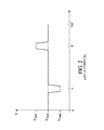
- the device 1 has a position "a” in which the angular velocity "V” of peripheral movement of the preform is decelerated (V min) with respect to the average speed (v avg).
- the "a" position may coincide with the entry of the preform into a low-pitch conveying equipment, such as a preform heating furnace which may have a 50 mm pitch between the preforms.
- a low-pitch conveying equipment such as a preform heating furnace which may have a 50 mm pitch between the preforms.
- V max the peripheral speed
- the position "b” may coincide with the delivery of the preform to a high-pitch conveying equipment, such as a blowing machine may have a pitch of 500 mm between the blowing stations.
- the device 1 is limited in the scroll speed change coefficient that can be obtained. Indeed, the greater the angular movement of the gripping arm 5, the greater the distance of the gripper 9 to the axis of rotation of the wheel 4 varies.
- two cam-controlled arms were developed. In addition to the cam path 3 controlling the relative angular position of the arm 5, is added another camming path controlling a radial translation of the clamp 9 on the arm 5. There is a need to obtain a scroll speed change of the objects with a simpler mechanism.
- the device 1 is limited in cadence, that is to say in the number of objects transferred per hour. This limit is reached faster than the rate of change of scroll speed is high. Indeed, the increase in the coefficient causes a slope 3b more inclined to further accelerate or decelerate locally the clamp 9. This results in mechanical stresses even higher than the wheel 4 rotates quickly. A need exists to obtain a coefficient of change of speed of scrolling less limited in time.
- the invention proposes a device for increasing the pitch for positive transfer of objects, a transfer mechanism and a preform blowing installation that meet at least one of the aforementioned needs.
- An object of the invention is to simplify the pitch increase device and / or to make it less limited in the rate of transferred objects.
- Such a device is mainly adapted to transfer objects whose section is circular and corresponds to the reference circle.
- the object transferred may have a guide section cooperating with the notches which is not purely circular.
- the guide section of the transferred object is then advantageously inscribed in the reference circle.
- said object slides along the first guide being pushed by the upstream side of the notch of the first wheel.
- the downstream flank of the notch of the second wheel that will receive this object does not interfere with this object although this notch of the second wheel has a peripheral speed faster than the object.
- the same object is pushed by the upstream side of the notch of the second wheel and the object slides along the second guide.
- the downstream flank of the notch of the first wheel that this object has just left does not interfere with the object that is moving away. In other words, the object could pass from the first wheel with a low peripheral scroll speed to the second wheel with a higher peripheral scroll speed and this in a simple way. In addition, there is no fast moving part.
- the pitch increasing device is then less limited in the rate of objects to be transferred than the device 1 described above.
- the downstream edge of each of the notches of at least one of the wheels is defined by the casing of the set of reference circles of the notch corresponding to said notch in the opposite wheel, during the rotation of the wheels.
- the downstream flank of the notches of the second wheel is conjugated to the input of a reference circle in said notch.
- this notch of the second wheel begins to hold the object before it arrives at the median plane, it allows to properly press the object on the upstream side of the notch of the first wheel.
- the downstream side of each of the notches of the first wheel is conjugated to the output of a reference circle of the second wheel out of this notch. This allows this notch to continue holding the object beyond the median plane. This makes it possible to flatten the object on the upstream side of the notch of the second wheel.
- the centers of the reference circles of each of the notches of a wheel are distributed along a circle coaxial with the axis of rotation of the corresponding wheel.
- the connecting mechanism is designed to secure the rotation of the first notched wheel and the rotation of the second notched wheel so that periodically the center of the reference circle of a notch of the first wheel reaches the plane. median simultaneously with the arrival of the center of the reference circle of a notch of the second wheel.
- the invention also relates to a transfer mechanism consisting of a first pitch-increasing device, followed by a second pitch-increasing device.
- the second wheel of the first device is the first wheel of the second device.
- the successive accumulation of two pairs of notched wheels makes it possible to multiply the rate of increase of the pitch. This also allows the second wheel of the second device to rotate in the same direction of rotation as the first wheel of the first device. This simplifies the implementation of the transfer mechanism.
- Each of the pitch increasing devices has a rate of increase equal to the second peripheral step divided by the first peripheral step.
- the downstream edge of each of the notches of the wheel common to the first and second devices is defined by the envelope of the set of reference circles of the notch corresponding to said notch in the opposite wheel belonging to the device of more great rate of increase, when rotating the wheels. This allows the notches of the common wheel to be optimized for the wheel pair of greater rate of pitch increase.
- the diameter and the number of notches of the wheels of the second pitch-increasing device are adapted so that the two rates of increase are similar.
- the notches of the wheel common to the two pitch increasing devices are substantially optimized both for their cooperation with the notches of the first wheel of the first device and with the notches of the second wheel of the second device.
- the auxiliary transfer mechanism comprises an aforementioned pitch-increasing device or comprises a aforementioned transfer mechanism.
- a device 50 comprises a first wheel 51 rotated by a drive means not shown in a direction 52 indicated by the arrow.
- the first wheel 51 is movable about a first axis 53 of rotation and comprises a succession of first notches 54a, 54b, 54c, 54d and is surrounded by a first guide 55 circular and coaxial with the first axis 53.
- the device 50 comprises a second wheel 56 movable in rotation about a second axis 57 of rotation.
- the device 50 comprises a mechanism for connecting the rotations of the first and second wheels 51, 56 so that the wheel 56 is driven in a direction opposite to the direction of rotation of the first wheel 51.
- the first and second axes 53, 57 of rotation are substantially parallel and contained in a median plane 58 .
- the second wheel 56 also has a succession of second notches 59a, 59b, 59c and is surrounded by a second guide 60 circular and coaxial with the second axis 57.
- Each of the first notches 54a, 54b, 54c, 54d have a concave shape open radially outwardly of the first wheel 51 and is constituted, on either side of the point of the concave shape closest to the first axis 53, a first upstream flank 61a, 61b, 61c, 61d and a first downstream flank 62a, 62b, 62c, 62d.
- each of the second notches 59a, 59b, 59c has a concave shape open radially outwardly of the second wheel 56 and is constituted, on either side of the point of the concave shape closest to the second axis 57 by a second upstream flank 63a, 63b, 63c and a second downstream flank 64a, 64b, 64c.
- the downstream side is the one that passes through the median plane 58 between the axes 53, 57 the first and the upstream side is the one that passes through it last.
- the direction of rotation of the first and second wheels 51, 56 also makes it possible to define an upstream side of the median plane 58 which is the one through which the notches of the two Wheels 51, 56 approach the median plane 58 between the axes 53, 57.
- the other side of the median plane 58 is a downstream side.
- the first guide 55 extends from the median plane 58 and surrounds the first wheel 51 on the upstream side of the median plane 58.
- the second guide 60 extends from the median plane 58 and surrounds the second wheel 56 on the downstream side of the median plane 58.
- a reference circle is defined which is circumscribed between the first corresponding upstream flank 61a, 61b, 61c, 61d and the first guide 55.
- a reference circle is defined which is circumscribed between the corresponding second upstream flank 63a, 63b, 63c and the second guide 60.
- the reference circles of the first notches have centers 65a, 65b, 65c, 65d distributed equidistantly along a path 66 in a first peripheral step 67 .
- the reference circles of the second recesses have centers 68a, 68b, 68c divided equidistantly along a path 69 according to a second step 70 device.
- the reference circles of the first notches are all of the same diameter.
- the reference circles of the second notches are advantageously of the same diameter and are also advantageously identical to the diameter of the reference circles of the first notches.
- the trajectories 66, 69 are circular and coaxial with the axis 53, 57 corresponding rotation. However, slight differences in diameter are possible without preventing the operation of the device 50.
- the first and second upstream flanks are circular. They may, however, be constituted by two abutment zones circumscribed to the reference circle of the corresponding notch.
- the trajectories 66, 69 are tangent to each other at the point of intersection with the median plane 58.
- the trajectories 66, 69 may not have a common point or be intersecting provided that their point of intersection with the median plane 58 remains close to the diameters of the reference circles.
- the rotational driving means and the rotational linking mechanism are designed so that periodically a center of the reference circle of the first notches (the center 65c in figure 3 ) reaches the median plane at the same time as a reference circle center of the second notches (center 68b in figure 3 ). This moment will be called a moment of coincidence.
- the first wheel 51 is driven at such a speed that the center 65b of the reference circle immediately upstream of the median plane 58 passes through the first peripheral step 67, while the second wheel 56 is driven at a speed such that the center 68a of the reference circle immediately upstream of the median plane 58 traverses the second peripheral pitch.
- an object such as a preform, having a circular section 71 substantially equal to the diameter common to all the reference circles can be received between the first notch 54b and the first guide 55, be pushed by the first upstream flank 61b, slide along the first guide 55 to the median plane 58.
- This object can then be supported by the corresponding second notch 59a, then be pushed by the second upstream flank 63a and slide along the second guide 60.
- the successive objects are separated from each other. others from a distance equal to the first peripheral step 67 and then transit along the second guide 60 where they are then spaced a distance equal to the second peripheral pitch 70.
- the figure 4 illustrates the position of the objects in the notches after a duration following the moment of coincidence of the figure 3 equal to one quarter of the period between two moments of coincidence. That is, the center 65c of the reference circle of the first notch 54c has traveled a quarter of the first peripheral pitch 67 and the center 68b of the reference circle of the second notch 59b has traveled a quarter of the second pitch 70 peripheral. In other words, the first downstream flank 62c is sufficiently far from the center 65c so that the object driven by the second notch 59b does not interfere with the first wheel 51.
- the center 65b of the reference circle of the notch 54b is upstream of the median plane 58 by a distance equal to three quarters of the first peripheral pitch 67.
- the second downstream flank 64a is sufficiently far from the center 68a for the object driven by the first notch 54b does not interfere with second wheel 56.
- the reference circle of the second notch 59b along the first sidewall 62c downstream This allows the slot 54c to continue to press the object supported by the second slot 59b against the second side 63b upstream.
- the reference circle of the first notch 54b runs along the second sidewall 64b downstream. This allows the second notch 59a to retain the object of the first notch 54b and hold it pressed against the first flank 61b upstream.
- the object transferred is a preform 72 having an axis 73 and comprising a neck 74, a flange 75 and a main portion 76 intended to be stretched and blown.
- the guide section 71 of the preform 72 is located below the flange 75 on the side of the main portion 76.
- the guide section 71 is cylindrical and coaxial with the axis 73 and the flange 75 extends radially beyond the guide section 71.
- the first and second wheels 51, 56 are machined in plates of similar thickness and each having an upper surface 77 .
- the wheels are arranged so that their upper surfaces 77 are at the same height.
- the guide section 71 is gripped by the first notch 54c and by the second notch 59b opposite ( figure 3 ).
- the flange 75 is then substantially supported by a half on the upper surface 77 of the first wheel 51 and substantially by another half on the upper surface 77 of the second wheel 56. This allows the axis 73 of the preform 72 to remain substantially vertical and parallel to the first and second axes 53, 57 of rotation.
- the first guide 55 comprises a main portion 78 and an extension 79.
- the main portion 78 has a surface 78a located at the same height as the upper surfaces 77 of the two wheels 51, 56.
- the flange 75 is supported firstly on the upper surface 77 of the first wheel 51 and secondly on the upper surface 78a of the main part 78.
- the two parts of the flange 75 in support are diametrically opposite with respect to the axis 73 of the flange, which gives good mechanical stability to the preform 72.
- the main portion 78 surrounds the first wheel 51 to the circle 69 of the second wheel 56.
- the extender 79 takes over the main portion 78 to continue holding the preform 72 in the first notch until the preform 72 reaches the median plane 58.
- the neck 74 has an opening 74a, also called a drinking head 74a, a thread 74b extending between the opening 74a and the collar 75.
- the neck has an edge 74c whose radially outer surface is cylindrical and smooth and extends axially on a few millimeters high from the rim 74a to the thread 74b.
- Extender 79 is a wire that extends above upper surfaces 78a, 77 at the height of smooth edge 74c.
- the extension 79 can thus guide the preform 72 as it enters the second notch 59a.
- the extension 79 makes it possible to maintain the axis 73 of the preform 72 in vertical position while the flange 75 leaves the main portion 78 of the first guide 55 to slide over the second wheel 56.
- the extender 79 keeps the guide section 71 pressed against the first flank 61b, 61c upstream and prevents it from leaving the location determined by the reference circle of the first notch 54b, 54c.
- the guide section 71 can enter the second notch 59a, 59b without hitting the second wheel 56.
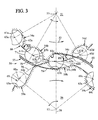
- a preform blowing installation 100 comprises successively following the path of the preforms 72: a preheating furnace 101 , an auxiliary transfer mechanism 102 , a main transfer mechanism 103 and a blowing machine 104 .
- the preheating furnace 101 comprises a chain 105, equipped with a succession of gripping mechanisms preforms 72 by their neck 74. This mechanism is often called “spin”. Along the chain 105, the preforms 72 are spaced apart from each other by a distance 106 that we will call “no primary device 106". To reduce the size of the oven, it is often sought to increase the density of the preforms 72 in the oven.
- the pitch 106 primary device may be 50 mm for example.
- the chain 105 is driven by two wheels 107 , one of which, the wheel A, is located at least partly outside the oven 101.
- the spinners withdraw preforms 72 and these are taken in charge between notches 108 of the wheel A and a guide 109 surrounding the wheel A.
- the wheel A also cooperates with a preform feed wheel 110 .
- the auxiliary transfer mechanism 102 is composed of first and second pitch increasing devices 111 and 112, respectively , as previously described.
- the first device 111 for increasing pitch is constituted by the wheel A, as the first wheel, accompanied by its guide 109, and by a wheel B, as the second wheel, accompanied by a guide 113.
- the preforms 72 are driven by the wheel B in a peripheral pitch 114 which may be 70 mm for example.
- the first pitch increasing device 111 has a rate of increase of 1.4.
- the second pitch increasing device 112 is constituted by the wheel B, as the first wheel accompanied by its guide 113, and by a wheel C as a second wheel accompanied by a guide 115.
- the wheel B is common to the first and second pitch increasing devices 111, 112.
- the preforms 112 are driven by the wheel C in a peripheral pitch 116 which may be 120 mm for example and which we will call "pitch 116 intermediate device".
- the second pitch increasing device 112 has a rate of increase of 1.71.
- the main transfer mechanism 103 comprises a series of arms 117 on a wheel (not shown) with an axis 118. Each of the arms 117 is rotatable about an auxiliary axis 119 . The various axes 119 are distributed along a circle coaxial with the axis 118. A single arm 117 has been shown. Each arm 117 comprises a clamp 120 whose radial relative position is controlled by a cam path 121 and whose relative angular position is controlled by a cam path 122 .
- the main transfer mechanism 103 has a mean preform drive speed which is slowed to coincide with the wheel C at the intermediate peripheral pitch 116 and which is accelerated with respect to the blowing machine 104 to coincide with a pitch 123 final device.
- the final peripheral pitch 123 corresponds to the distance between two successive stretch blow molding stations 124 . This distance may be 500 mm for example so that the main transfer mechanism 103 then has a step increase rate of 4.16.
- the wheel B is illustrated in its portion which cooperates with the wheel A.
- the wheel B has notches 129 comprising a downstream sidewall 126 which is conjugated with the displacement of the reference circles driven by the wheel C with which the wheel B has the rate of increase of not the highest.
- a dotted line 126a is shown conjugated with the reference circles driven by wheel A is shown in dotted lines.
- the profile of the downstream flank 126 which has been retained is one of the conjugate profiles which has the minimum of material .
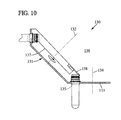
- a pitch increasing device 130 may be made with a first wheel 131 movable about a first axis 132 and a second wheel 133 movable about a second axis 134.
- the first wheel 131 has notches 135 designed to be in the same plane as the second wheel 133 when this notch comes opposite the wheel 133.
- the first and second axes 132, 134 are intersecting and are contained in a median plane 136.
- the device 130 includes a cone-shaped guide 137 surrounding the first wheel 131, and an extension 138 extending the preform guide to the median plane 136 at a location where the conical guide 137 will interfere with the second wheel 133.
- first and second axes 132, 134 could be strictly non-coplanar.
- the median plane of the pitch increase device would then be the one relative to which the first and second axes would generally have the minimum angle.
Abstract
Description
L'invention concerne le domaine des équipements de convoyage positif et individuel d'objets le long d'une trajectoire de convoyage. Un convoyage est positif et individuel lorsque chacun des objets est tenu ou guidé lors du convoyage. Les objets convoyés sont répartis le long de la trajectoire de convoyage selon un pas périphérique.The invention relates to the field of positive and individual conveying equipment objects along a conveying path. A conveying is positive and individual when each object is held or guided during the conveying. The conveyed objects are distributed along the conveying path according to a peripheral step.
L'invention concerne notamment le domaine des mécanismes de transfert des objets entre deux équipements de convoyage positif et individuel d'objets.The invention relates in particular to the field of mechanisms for transferring objects between two positive and individual conveying equipment objects.
L'invention concerne en particulier des dispositifs d'augmentation de pas qui permettent au mécanisme de transfert de transférer positivement et individuellement des objets depuis un équipement de convoyage amont selon un premier pas périphérique vers un équipement de convoyage aval selon un deuxième pas périphérique strictement supérieur au premier pas périphérique.The invention particularly relates to pitch increase devices which enable the transfer mechanism to positively and individually transfer objects from an upstream conveying equipment according to a first peripheral step to a downstream conveying equipment according to a second, strictly superior peripheral step. at the first peripheral step.
L'invention concerne par exemple le transfert d'objets de type préformes destinées à être transformées en un récipient par soufflage ou étirage-soufflage.The invention relates for example to the transfer of preform type objects intended to be converted into a container by blowing or stretch-blow molding.
Un mécanisme bien connu de transfert est constitué par une paire de roues à encoches. Les deux roues sont mobiles en rotation autour d'axes parallèles contenus dans un plan médian et sont synchronisées entre elles. Le mécanisme comprend un premier guide entourant la première roue d'un côté du plan médian et comprend un deuxième guide entourant la deuxième roue du côté opposé du plan médian. Les diamètres des roues peuvent être différents mais la distance périphérique entre deux encoches successives sont identiques pour les deux roues. Ce mécanisme de transfert n'est pas un dispositif d'augmentation de pas.A well-known transfer mechanism is a pair of notched wheels. The two wheels are movable in rotation about parallel axes contained in a median plane and are synchronized with each other. The mechanism includes a first guide surrounding the first wheel on one side of the median plane and includes a second guide surrounding the second wheel on the opposite side of the median plane. The diameters of the wheels may be different but the peripheral distance between two successive notches are identical for the two wheels. This transfer mechanism is not a step-up device.
On connaît également le dispositif 1 illustré aux
Le chemin 3 de came présente une zone 3a amont et une zone 3c aval qui sont toutes les deux circulaires et qui sont raccordées par une rampe 3b inclinée par rapport au cercle 7. "a1" est la position de l'axe 6 lorsque le galet 8 est à l'extrémité amont de la rampe 3b et la préforme occupe un emplacement "p1" illustré en traits mixtes sur la figure. "a3" est la position de l'axe 6 lorsque le galet 8 est à l'extrémité aval de la rampe 3b et la préforme occupe une place "p3". "A" est le secteur angulaire parcouru par l'axe 6 entre les positions "a1" et "a3". Lorsque la roue 4 parcourt le secteur angulaire "A", la préforme passe de "p1" à "p3". Si le bras 5 de préhension était monté fixe sur la roue 4, la préforme aurait parcouru le chemin de "p1'" à "p3'" qui est plus court que le chemin de "p1" à "p3". Le dispositif 1 permet donc bien d'augmenter localement le pas parcouru par la préforme à l'endroit de la rampe 3b.The
Comme illustré en
Cependant, le dispositif 1 est limité dans le coefficient de changement de vitesse de défilement susceptible d'être obtenu. En effet, plus le débattement angulaire du bras 5 de préhension est important, plus la distance de la pince 9 à l'axe de rotation de la roue 4 varie. Pour explorer des coefficients de changement de vitesse plus élevés, on a développé des bras à deux degrés de liberté commandés par came. En plus du chemin 3 de came commandant la position angulaire relative du bras 5, est ajouté un autre chemin de came commandant une translation radiale de la pince 9 sur le bras 5. Il existe un besoin d'obtenir un changement de vitesse de défilement des objets avec un mécanisme plus simple.However, the
Par ailleurs, le dispositif 1 est limité en cadence, c'est-à-dire en nombre d'objets transférés par heure. Cette limite est d'autant plus rapidement atteinte que le coefficient de changement de vitesse de défilement est élevé. En effet, l'augmentation du coefficient entraîne une pente 3b plus inclinée afin de plus accélérer ou décélérer localement la pince 9. Cela se traduit par des contraintes mécaniques d'autant plus élevées que la roue 4 tourne rapidement. Un besoin existe d'obtenir un coefficient de changement de vitesse de défilement moins limité en cadence.Moreover, the
L'invention propose un dispositif d'augmentation de pas pour transfert positif d'objets, un mécanisme de transfert et une installation de soufflage de préformes qui répondent à au moins l'un des besoins précités.The invention proposes a device for increasing the pitch for positive transfer of objects, a transfer mechanism and a preform blowing installation that meet at least one of the aforementioned needs.
Un but de l'invention est de simplifier le dispositif d'augmentation de pas et/ou de le rendre moins limité en débit d'objets transférés.An object of the invention is to simplify the pitch increase device and / or to make it less limited in the rate of transferred objects.
Selon un mode de réalisation, le dispositif d'augmentation de pas pour transfert positif et individuel d'objets, comprend :
- une première et une deuxième roues à encoches, mobiles respectivement autour d'un premier et d'un deuxième axe de rotation, lesquels axes sont sensiblement contenus dans un plan médian ; les encoches de chaque roue étant réparties respectivement selon un premier pas périphérique et un deuxième pas périphérique,
- un mécanisme de liaison desdites rotations synchronisant périodiquement les encoches des deux roues,
- un moyen d'entraînement en rotation des roues, définissant un coté amont et un coté aval du plan médian,
- un premier et un deuxième guides entourant respectivement la première et la deuxième roue et s'étendant à partir du plan médian en direction respectivement du coté amont et du coté aval, et disposés pour maintenir l'objet dans l'encoche correspondante. Le deuxième pas périphérique est strictement supérieur au premier pas périphérique. Chacune des encoches est délimitée par un flanc amont coopérant avec le guide correspondant pour circonscrire un cercle de référence et par un flanc aval. Pour chaque roue, le flanc aval des encoches est conçu pour ne pas interférer lors de la rotation des roues avec le cercle de référence de l'encoche correspondante de la roue opposée.
- first and second notched wheels respectively movable about a first and a second axis of rotation, which axes are substantially contained in a median plane; the notches of each wheel being distributed respectively according to a first peripheral step and a second peripheral step,
- a link mechanism of said rotations periodically synchronizing the notches of the two wheels,
- means for driving the wheels in rotation, defining an upstream side and a downstream side of the median plane,
- first and second guides respectively surrounding the first and second wheels and extending from the median plane respectively towards the upstream side and the downstream side, and arranged to hold the object in the corresponding notch. The second peripheral step is strictly greater than the first peripheral step. Each of the notches is delimited by an upstream flank cooperating with the corresponding guide to circumscribe a reference circle and a downstream flank. For each wheel, the downstream side of the notches is designed not to interfere with the rotation of the wheels with the reference circle of the corresponding notch of the opposite wheel.
Un tel dispositif est principalement adapté à transférer des objets dont une section est circulaire et correspond au cercle de référence. Toutefois, l'objet transféré peut présenter une section de guidage coopérant avec les encoches qui n'est pas purement circulaire. La section de guidage de l'objet transféré est alors avantageusement inscrite dans le cercle de référence. Ainsi, ledit objet glisse le long du premier guide en étant poussé par le flanc amont de l'encoche de la première roue. Le flanc aval de l'encoche de la deuxième roue qui va recevoir cet objet n'interfère pas avec cet objet bien que cette encoche de la deuxième roue présente une vitesse périphérique plus rapide que l'objet. Une fois passé le plan médian, le même objet est poussé par le flanc amont de l'encoche de la deuxième roue et l'objet glisse le long du deuxième guide. Le flanc aval de l'encoche de la première roue que cet objet vient de quitter n'interfère pas avec l'objet qui s'éloigne. Autrement dit, l'objet a pu passer de la première roue avec une vitesse de défilement périphérique faible à la deuxième roue avec une vitesse de défilement périphérique plus élevée et ceci de manière simple. De plus, il n'y a pas de pièce en mouvement rapide. Le dispositif d'augmentation de pas est alors moins limité en débit d'objets à transférer que le dispositif 1 décrit précédemment.Such a device is mainly adapted to transfer objects whose section is circular and corresponds to the reference circle. However, the object transferred may have a guide section cooperating with the notches which is not purely circular. The guide section of the transferred object is then advantageously inscribed in the reference circle. Thus, said object slides along the first guide being pushed by the upstream side of the notch of the first wheel. The downstream flank of the notch of the second wheel that will receive this object does not interfere with this object although this notch of the second wheel has a peripheral speed faster than the object. Once past the median plane, the same object is pushed by the upstream side of the notch of the second wheel and the object slides along the second guide. The downstream flank of the notch of the first wheel that this object has just left does not interfere with the object that is moving away. In other words, the object could pass from the first wheel with a low peripheral scroll speed to the second wheel with a higher peripheral scroll speed and this in a simple way. In addition, there is no fast moving part. The pitch increasing device is then less limited in the rate of objects to be transferred than the
Avantageusement, le flanc aval de chacune des encoches d'au moins une des roues est défini par l'enveloppe de l'ensemble des cercles de référence de l'encoche correspondante à ladite encoche dans la roue opposée, lors de la rotation des roues. Autrement dit, le flanc aval des encoches de la deuxième roue est conjugué à l'entrée d'un cercle de référence dans ladite encoche. Ainsi, cette encoche de la deuxième roue commence à tenir l'objet avant que celui-ci arrive au plan médian, cela permet de bien plaquer l'objet sur le flanc amont de l'encoche de la première roue. De même, le flanc aval de chacune des encoches de la première roue est conjugué à la sortie d'un cercle de référence de la deuxième roue hors de cette encoche. Cela permet à cette encoche de continuer à tenir l'objet au-delà du plan médian. Cela permet de bien plaquer l'objet sur le flanc amont de l'encoche de la deuxième roue.Advantageously, the downstream edge of each of the notches of at least one of the wheels is defined by the casing of the set of reference circles of the notch corresponding to said notch in the opposite wheel, during the rotation of the wheels. In other words, the downstream flank of the notches of the second wheel is conjugated to the input of a reference circle in said notch. Thus, this notch of the second wheel begins to hold the object before it arrives at the median plane, it allows to properly press the object on the upstream side of the notch of the first wheel. Similarly, the downstream side of each of the notches of the first wheel is conjugated to the output of a reference circle of the second wheel out of this notch. This allows this notch to continue holding the object beyond the median plane. This makes it possible to flatten the object on the upstream side of the notch of the second wheel.
Avantageusement, les centres des cercles de référence de chacune des encoches d'une roue sont répartis le long d'un cercle coaxial à l'axe de rotation de la roue correspondante.Advantageously, the centers of the reference circles of each of the notches of a wheel are distributed along a circle coaxial with the axis of rotation of the corresponding wheel.
Avantageusement, le mécanisme de liaison est conçu pour solidariser la rotation de la première roue à encoches et la rotation de la deuxième roue à encoches de manière que périodiquement le centre du cercle de référence d'une encoche de la première roue arrive au plan médian simultanément à l'arrivée du centre du cercle de référence d'une encoche de la deuxième roue.Advantageously, the connecting mechanism is designed to secure the rotation of the first notched wheel and the rotation of the second notched wheel so that periodically the center of the reference circle of a notch of the first wheel reaches the plane. median simultaneously with the arrival of the center of the reference circle of a notch of the second wheel.
L'invention porte également sur un mécanisme de transfert constitué d'un premier dispositif d'augmentation de pas précité, suivi d'un deuxième dispositif d'augmentation de pas précité. La deuxième roue du premier dispositif est la première roue du deuxième dispositif. Le cumul successif de deux paires de roues à encoches permet de multiplier les taux d'augmentation du pas. Cela permet également que la deuxième roue du deuxième dispositif tourne dans le même sens de rotation que la première roue du premier dispositif. Cela simplifie l'implantation du mécanisme de transfert.The invention also relates to a transfer mechanism consisting of a first pitch-increasing device, followed by a second pitch-increasing device. The second wheel of the first device is the first wheel of the second device. The successive accumulation of two pairs of notched wheels makes it possible to multiply the rate of increase of the pitch. This also allows the second wheel of the second device to rotate in the same direction of rotation as the first wheel of the first device. This simplifies the implementation of the transfer mechanism.
Chacun des dispositifs d'augmentation de pas présente un taux d'augmentation égale au deuxième pas périphérique divisé par le premier pas périphérique. Avantageusement, le flanc aval de chacune des encoches de la roue commune au premier et au deuxième dispositifs est défini par l'enveloppe de l'ensemble des cercles de référence de l'encoche correspondante à ladite encoche dans la roue opposée appartenant au dispositif de plus grand taux d'augmentation, lors de la rotation des roues. Cela permet aux encoches de la roue commune d'être optimisées pour la paire de roues de plus grand taux d'augmentation de pas. Avantageusement, le diamètre et le nombre d'encoches des roues du deuxième dispositif d'augmentation de pas sont adaptés pour que les deux taux d'augmentation soient voisins. Ainsi, les encoches de la roue commune aux deux dispositifs d'augmentation de pas sont sensiblement optimisées à la fois pour leur coopération avec les encoches de la première roue du premier dispositif et avec les encoches de la deuxième roue du deuxième dispositif.Each of the pitch increasing devices has a rate of increase equal to the second peripheral step divided by the first peripheral step. Advantageously, the downstream edge of each of the notches of the wheel common to the first and second devices is defined by the envelope of the set of reference circles of the notch corresponding to said notch in the opposite wheel belonging to the device of more great rate of increase, when rotating the wheels. This allows the notches of the common wheel to be optimized for the wheel pair of greater rate of pitch increase. Advantageously, the diameter and the number of notches of the wheels of the second pitch-increasing device are adapted so that the two rates of increase are similar. Thus, the notches of the wheel common to the two pitch increasing devices are substantially optimized both for their cooperation with the notches of the first wheel of the first device and with the notches of the second wheel of the second device.
L'invention porte en outre sur une installation de soufflage de préformes, comprenant :
- un four de chauffage des préformes comprenant un mécanisme de convoyage des préformes, présentant un pas périphérique primaire de défilement des préformes,
- une machine de soufflage comprenant une pluralité de station de soufflage des préformes, présentant un pas périphérique final de défilement des stations de soufflage,
- un mécanisme de transfert principal, conçu pour recevoir des préformes selon un pas périphérique intermédiaire strictement inférieur au pas périphérique final et strictement supérieur au pas périphérique primaire, et à mettre les préformes à disposition de la machine de soufflage,
- un mécanisme de transfert auxiliaire, conçu pour recevoir des préformes du four de chauffage selon le pas périphérique primaire et à mettre à disposition du mécanisme de transfert principal, les préformes selon le pas périphérique intermédiaire.
- a preform heating furnace comprising a preform conveying mechanism having a primary peripheral pitch of the preforms,
- a blowing machine comprising a plurality of preform blowing station, having a final peripheral step for moving the blowing stations,
- a main transfer mechanism, designed to receive preforms at an intermediate peripheral pitch strictly less than the final peripheral pitch and strictly greater than the primary peripheral pitch, and to make the preforms available to the blowing machine,
- an auxiliary transfer mechanism, designed to receive preforms of the heating furnace according to the primary peripheral pitch and to provide the main transfer mechanism, the preforms according to the intermediate peripheral step.
Le mécanisme de transfert auxiliaire comprend un dispositif d'augmentation de pas précité ou comprend un mécanisme de transfert précité.The auxiliary transfer mechanism comprises an aforementioned pitch-increasing device or comprises a aforementioned transfer mechanism.
Le fait que le transfert entre le four de chauffage de préformes et la machine de soufflage soit réparti sur deux mécanismes de transfert différents montés en série l'un après l'autre, fait que chacun des mécanismes de transfert doit prendre en charge un taux d'augmentation du pas plus faible. Si l'un des mécanismes est un dispositif 1 décrit aux
-
les
figures 1 et2 illustrent respectivement une vue de dessus et un graphe de vitesses d'un dispositif d'adaptation de pas périphérique de l'art antérieur.
La présente invention sera mieux comprise à l'étude de la description détaillée de quelques modes de réalisation pris à titre d'exemples nullement limitatifs et illustrés par les dessins annexés sur lesquels :thefigures 1 and2 respectively illustrate a top view and a velocity graph of a peripheral pitch matching device of the prior art.
The present invention will be better understood on studying the detailed description of some embodiments taken as non-limiting examples and illustrated by the appended drawings in which: -
les
figures 3 à 6 illustrent une vue de dessus selon la flèche III de lafigure 7 , d'un mode de réalisation de dispositif d'augmentation de pas,theFigures 3 to 6 illustrate a view from above according to the arrow III of thefigure 7 , an embodiment of a device for increasing the pitch, -
la
figure 7 est une coupe partielle selon la ligne VII-VII de lafigure 3 , illustrant un guide,thefigure 7 is a partial section along line VII-VII of thefigure 3 , illustrating a guide, -
la
figure 8 est une vue de dessus d'une installation de soufflage de préformes, utilisant un mécanisme de transfert comprenant un premier dispositif d'augmentation de pas et un deuxième dispositif d'augmentation de pas selon lesfigures 3 à 7 ,thefigure 8 is a top view of a preform blowing installation, using a transfer mechanism comprising a first pitch increasing device and a second pitch increasing device according to theFigures 3 to 7 , -
la
figure 9 illustre la roue commune au premier et au deuxième dispositif d'augmentation de pas de lafigure 8 ,thefigure 9 illustrates the wheel common to the first and the second pitch increasing device of thefigure 8 , -
la
figure 10 est une vue en coupe selon le plan médian d'un deuxième mode de réalisation de dispositif d'augmentation de pas.thefigure 10 is a sectional view along the median plane of a second embodiment of a pitch-increasing device.
Comme illustré sur la
De même, le dispositif 50 comprend une deuxième roue 56 mobile en rotation autour d'un deuxième axe 57 de rotation. Le dispositif 50 comprend un mécanisme de liaison des rotations des première et deuxième roues 51, 56 de manière que la roue 56 soit entraînée dans un sens opposé au sens de rotation de la première roue 51. Les premier et deuxième axes 53, 57 de rotation sont sensiblement parallèles et contenus dans un plan 58 médian. La deuxième roue 56 présente également une succession de deuxièmes encoches 59a, 59b, 59c et est entourée par un deuxième guide 60 circulaire et coaxial au deuxième axe 57.Similarly, the
Chacune des premières encoches 54a, 54b, 54c, 54d présentent une forme concave ouverte radialement vers l'extérieur de la première roue 51 et est constituée, de part et d'autre du point de la forme concave la plus proche du premier axe 53, d'un premier flanc amont 61a, 61b, 61c, 61d et d'un premier flanc aval 62a, 62b, 62c, 62d. De même, chacune des deuxièmes encoches 59a, 59b, 59c présente une forme concave ouverte radialement vers l'extérieur de la deuxième roue 56 et est constituée, de part et d'autre du point de la forme concave la plus proche du deuxième axe 57 par un deuxième flanc amont 63a, 63b, 63c et par un deuxième flanc aval 64a, 64b, 64c. Pour chacune des premières et deuxièmes encoches, le flanc aval est celui qui traverse le plan 58 médian entre les axes 53, 57 le premier et le flanc amont est celui qui le traverse en dernier.Each of the
Le sens de rotation des premières et deuxièmes roues 51, 56 permet également de définir un côté amont du plan 58 médian qui est celui par où les encoches des deux roues 51, 56 s'approchent du plan 58 médian entre les axes 53, 57. L'autre côté du plan 58 médian est un côté aval. Le premier guide 55 s'étend à partir du plan 58 médian et entoure la première roue 51 du côté amont du plan 58 médian. De même, le deuxième guide 60 s'étend à partir du plan 58 médian et entoure la deuxième roue 56 du côté aval du plan 58 médian.The direction of rotation of the first and
Pour chacune des premières encoches 54a, 54b, 54c, 54d, on définit un cercle de référence qui est circonscrit entre le premier flanc amont 61a, 61b, 61c, 61d correspondant et le premier guide 55. De même, pour chacune des deuxièmes encoches 59a, 59b, 59c, on définit un cercle de référence qui est circonscrit entre le deuxième flanc amont 63a, 63b, 63c correspondant et le deuxième guide 60.For each of the
Les cercles de référence des premières encoches présentent des centres 65a, 65b, 65c, 65d répartis de manière équidistante le long d'une trajectoire 66 selon un premier pas 67 périphérique. De même, les cercles de référence des deuxièmes encoches présentent des centres 68a, 68b, 68c répartis de manière équidistante le long d'une trajectoire 69 selon un deuxième pas 70 périphérique.The reference circles of the first notches have
De manière avantageuse, les cercles de référence des premières encoches sont tous de même diamètre. De même, les cercles de référence des deuxièmes encoches sont avantageusement de même diamètre et sont également avantageusement identiques au diamètre des cercles de référence des premières encoches. Les trajectoires 66, 69 sont circulaires et coaxiales à l'axe 53, 57 de rotation correspondant. Toutefois, de légères différences de diamètre sont possibles sans empêcher le fonctionnement du dispositif 50.Advantageously, the reference circles of the first notches are all of the same diameter. Similarly, the reference circles of the second notches are advantageously of the same diameter and are also advantageously identical to the diameter of the reference circles of the first notches. The
De manière avantageuse mais non obligatoire, les premier et deuxième flancs amont sont circulaires. Ils peuvent toutefois être constitués par deux zones de butée circonscrites au cercle de référence de l'encoche correspondante.Advantageously but not obligatory, the first and second upstream flanks are circular. They may, however, be constituted by two abutment zones circumscribed to the reference circle of the corresponding notch.
De manière avantageuse, les trajectoires 66, 69 sont tangentes l'une à l'autre à l'endroit d'intersection avec le plan 58 médian. Toutefois, les trajectoires 66, 69 pourraient ne pas présenter de point commun ou être sécantes à condition que leur point d'intersection avec le plan 58 médian reste voisin en regard des diamètres des cercles de référence.Advantageously, the
Le moyen d'entraînement en rotation ainsi que le mécanisme de liaison des rotations (non représenté) sont conçus de manière que périodiquement, un centre du cercle de référence des premières encoches (le centre 65c en
Durant la période de temps s'écoulant entre deux instants de coïncidence, la première roue 51 est entraînée à une vitesse telle que le centre 65b du cercle de référence immédiatement en amont du plan 58 médian parcourt le premier pas 67 périphérique, pendant que la deuxième roue 56 est entraînée à une vitesse telle que le centre 68a du cercle de référence immédiatement en amont du plan 58 médian parcourt le deuxième pas 70 périphérique.During the period of time between two coincidence instants, the
On comprend qu'un objet, telle qu'une préforme, présentant une section 71 circulaire sensiblement égale au diamètre commun à l'ensemble des cercles de référence peut être reçu entre la première encoche 54b et le premier guide 55, être poussé par le premier flanc amont 61b, glisser le long du premier guide 55 jusqu'au plan 58 médian. Cet objet peut alors être pris en charge par la deuxième encoche 59a correspondante, être alors poussé par le deuxième flanc amont 63a et glisser le long du deuxième guide 60. Ainsi, le long du premier guide 55, les objets successifs sont séparés les uns des autres d'une distance égale au premier pas 67 périphérique puis transitent le long du deuxième guide 60 où ils sont alors espacés d'une distance égale au deuxième pas 70 périphérique. Il y a eu augmentation du pas séparant la succession des objets transférés sans pièce mobile.It is understood that an object, such as a preform, having a
On va à l'aide des
La
Dans ce même instant, le centre 65b du cercle de référence de l'encoche 54b est en amont du plan 58 médian d'une distance égale aux trois quarts du premier pas 67 périphérique. Le deuxième flanc aval 64a est suffisamment éloigné du centre 68a pour que l'objet entraîné par la première encoche 54b n'interfère pas avec la deuxième roue 56.At the same time, the
De préférence, comme illustré en
De même, comme visible aux
Dans une utilisation avantageuse du dispositif 50, illustrée en
La section 71 de guidage est cylindrique et coaxiale à l'axe 73 et la collerette 75 s'étend radialement au-delà de la section 71 de guidage. De plus, les première et deuxième roues 51, 56 sont usinées dans des plaques d'épaisseurs voisines et présentant chacune une surface 77 supérieure. Les roues sont disposées de manière que leurs surfaces 77 supérieures soient situées à la même hauteur. Ainsi, quand la préforme 72 est dans le plan 58 médian, la section 71 de guidage est enserrée par la première encoche 54c et par la deuxième encoche 59b en regard (
Le premier guide 55 comprend une partie 78 principale et un prolongateur 79. La partie 78 principale présente une surface 78a située à la même hauteur que les surfaces 77 supérieures des deux roues 51, 56. Dans une phase d'approche, lorsque la préforme 72 est guidée par la section 71 de guidage entre une première encoche et le premier guide 55, la collerette 75 est en appui d'une part sur la surface 77 supérieure de la première roue 51 et d'autre part sur la surface 78a supérieure de la partie principale 78. Les deux parties de la collerette 75 en appui sont diamétralement opposées par rapport à l'axe 73 de la collerette, ce qui confère une bonne stabilité mécanique à la préforme 72.The
Comme on le voit en
Le prolongateur 79 est un fil qui s'étend au-dessus des surfaces 78a, 77 supérieures, à la hauteur du bord 74c lisse. Le prolongateur 79 peut ainsi guider la préforme 72 pendant que celle-ci entre dans la deuxième encoche 59a. Le prolongateur 79 permet de maintenir l'axe 73 de la préforme 72 en position verticale pendant que la collerette 75 quitte la partie principale 78 du premier guide 55 pour glisser au-dessus de la deuxième roue 56. Le prolongateur 79 maintient la section 71 de guidage plaquée contre le premier flanc 61b, 61c amont et évite qu'elle ne quitte l'emplacement déterminé par le cercle de référence de la première encoche 54b, 54c. Ainsi, la section 71 de guidage peut entrer dans la deuxième encoche 59a, 59b sans heurter la deuxième roue 56.
Ce qui a été décrit pour le premier guide 55 est également présent de manière analogue dans le deuxième guide 60.What has been described for the
Comme illustré en
Le four 101 de préchauffage comprend une chaîne 105, équipée d'une succession de mécanismes de préhension des préformes 72 par leur goulot 74. Ce mécanisme est souvent appelé "tournette". Le long de la chaîne 105, les préformes 72 sont espacées les unes des autres d'une distance 106 que nous appellerons "pas 106 périphérique primaire". Pour réduire la dimension du four, on cherche souvent à augmenter la densité des préformes 72 dans le four. Le pas 106 périphérique primaire peut être de 50 mm par exemple.The preheating
La chaîne 105 est entraînée par deux roues 107 dont une, la roue A, est située au moins en partie à l'extérieur du four 101. Lorsque la chaîne 105 quitte le four 101 et commence à entourer la roue A, les tournettes se retirent des préformes 72 et ces dernières sont prises en charge entre des encoches 108 de la roue A et un guide 109 entourant la roue A. La roue A coopère également avec une roue 110 d'alimentation en préformes 72.The
Le mécanisme 102 de transfert auxiliaire est composé d'un premier et d'un deuxième dispositifs d'augmentation de pas, respectivement 111 et 112, tels que décrits précédemment. Le premier dispositif 111 d'augmentation de pas est constitué par la roue A, en tant que première roue, accompagnée de son guide 109, et par une roue B, en tant que deuxième roue, accompagnée d'un guide 113. Les préformes 72 sont entraînées par la roue B selon un pas 114 périphérique qui peut être de 70 mm par exemple. Dans cet exemple non limitatif, le premier dispositif 111 d'augmentation de pas présente un taux d'augmentation de 1,4.The
Le deuxième dispositif 112 d'augmentation de pas est constitué par la roue B, en tant que première roue accompagnée de son guide 113, et par une roue C en tant que deuxième roue accompagnée par un guide 115. Autrement dit, la roue B est commune au premier et au deuxième dispositifs 111, 112 d'augmentation de pas. Les préformes 112 sont entraînées par la roue C selon un pas 116 périphérique qui peut être de 120 mm par exemple et que nous appellerons "pas 116 périphérique intermédiaire". Dans cet exemple, le deuxième dispositif 112 d'augmentation de pas présente un taux d'augmentation de 1, 71.The second
Le mécanisme 103 de transfert principal comprend une série de bras 117 embarqués sur une roue (non représentée) d'axe 118. Chacun des bras 117 est mobile en rotation autour d'un axe 119 auxiliaire. Les différents axes 119 sont répartis le long d'un cercle coaxial à l'axe 118. Un seul bras 117 a été représenté. Chaque bras 117 comprend une pince 120 dont la position relative radiale est commandée par un chemin 121 de came et dont la position relative angulaire est commandée par un chemin 122 de came.The
Comme expliqué à l'aide de la
On comprend que le fait d'avoir séparé le transfert entre le four 101, avec un pas périphérique primaire de 50 mm et la machine de soufflage avec un pas périphérique final de 500 mm, entre deux mécanismes successifs de transfert 102, 103, a permis de réduire fortement le taux d'augmentation de pas devant être réalisée par le mécanisme 103 de transfert principal. Cela permet de moins incliner les rampes des chemins de came 121, 122 et d'augmenter la cadence générale de l'installation 100.It is understood that having separated the transfer between the
Dans la
Comme illustré en
Dans une variante, les premier et deuxième axes 132, 134 pourraient être non coplanaires strictement. Le plan médian du dispositif d'augmentation de pas serait alors celui par rapport auquel les premier et deuxième axes présenteraient globalement le minimum d'angle.In a variant, the first and
Claims (7)
Applications Claiming Priority (1)
| Application Number | Priority Date | Filing Date | Title |
|---|---|---|---|
| FR1256823A FR2993259B1 (en) | 2012-07-13 | 2012-07-13 | DEVICE FOR INCREASING PASTE FOR POSITIVE AND INDIVIDUAL TRANSFER OF OBJECTS |
Publications (2)
| Publication Number | Publication Date |
|---|---|
| EP2684822A1 true EP2684822A1 (en) | 2014-01-15 |
| EP2684822B1 EP2684822B1 (en) | 2014-12-03 |
Family
ID=47424986
Family Applications (1)
| Application Number | Title | Priority Date | Filing Date |
|---|---|---|---|
| EP13173813.0A Not-in-force EP2684822B1 (en) | 2012-07-13 | 2013-06-26 | Device to increase the step for positive and individual transfer of objects |
Country Status (3)
| Country | Link |
|---|---|
| EP (1) | EP2684822B1 (en) |
| CN (1) | CN103538913B (en) |
| FR (1) | FR2993259B1 (en) |
Cited By (3)
| Publication number | Priority date | Publication date | Assignee | Title |
|---|---|---|---|---|
| WO2016001332A1 (en) * | 2014-07-02 | 2016-01-07 | Serac Group | Container transport apparatus |
| IT201800007415A1 (en) * | 2018-07-23 | 2020-01-23 | GUIDE-NECK DEVICE FOR BOTTLING LINES | |
| EP3380420B1 (en) * | 2015-11-25 | 2022-04-20 | Esomatec GmbH | Device and method for separating and/or testing containers |
Families Citing this family (1)
| Publication number | Priority date | Publication date | Assignee | Title |
|---|---|---|---|---|
| DE102018208956A1 (en) * | 2018-06-06 | 2019-12-12 | Bausch + Ströbel Maschinenfabrik Ilshofen GmbH + Co. KG | turnout device |
Citations (3)
| Publication number | Priority date | Publication date | Assignee | Title |
|---|---|---|---|---|
| US4790741A (en) * | 1987-08-07 | 1988-12-13 | Toyo Seikan Kaisha, Ltd. | Apparatus for preparing heat-set plastic hollow vessel |
| WO2001042113A1 (en) * | 1999-12-08 | 2001-06-14 | Central Bottling International Limited | Handling apparatus for use in a bottling plant to handle bottles with neck rings |
| WO2011113710A1 (en) * | 2010-03-15 | 2011-09-22 | Crown Packaging Technology, Inc. | Container manufacture |
Family Cites Families (5)
| Publication number | Priority date | Publication date | Assignee | Title |
|---|---|---|---|---|
| FR2709264B1 (en) * | 1993-08-26 | 1995-10-27 | Sidel Sa | Installation for manufacturing containers by blowing plastic preforms. |
| ITRE20040039A1 (en) * | 2004-04-23 | 2004-07-23 | Sacmi | HANDLING OF BODIES OF POLYMERIC MATERIAL IN THE VISCOUS LIQUID STATE IN THE COMPRESSION FORMING OF PLASTIC OBJECTS. |
| US7632089B2 (en) * | 2004-05-07 | 2009-12-15 | Graham Packaging Pet Technologies, Inc. | Take out and cooling system and method |
| FR2895384B1 (en) * | 2005-12-26 | 2009-10-30 | Sidel Sas | DEVICE FOR SELECTIVELY TRANSFERRING ARTICLES WITH LARGE CADENCE, APPLICATION FOR SORTING BOTTLES, BLOWING MACHINE COMPRISING SUCH A DEVICE |
| CN102358025B (en) * | 2011-09-07 | 2014-04-16 | 铨宝工业股份有限公司 | Blow molding machine and shunting method thereof |
-
2012
- 2012-07-13 FR FR1256823A patent/FR2993259B1/en not_active Expired - Fee Related
-
2013
- 2013-06-26 EP EP13173813.0A patent/EP2684822B1/en not_active Not-in-force
- 2013-07-11 CN CN201310291324.0A patent/CN103538913B/en not_active Expired - Fee Related
Patent Citations (3)
| Publication number | Priority date | Publication date | Assignee | Title |
|---|---|---|---|---|
| US4790741A (en) * | 1987-08-07 | 1988-12-13 | Toyo Seikan Kaisha, Ltd. | Apparatus for preparing heat-set plastic hollow vessel |
| WO2001042113A1 (en) * | 1999-12-08 | 2001-06-14 | Central Bottling International Limited | Handling apparatus for use in a bottling plant to handle bottles with neck rings |
| WO2011113710A1 (en) * | 2010-03-15 | 2011-09-22 | Crown Packaging Technology, Inc. | Container manufacture |
Cited By (4)
| Publication number | Priority date | Publication date | Assignee | Title |
|---|---|---|---|---|
| WO2016001332A1 (en) * | 2014-07-02 | 2016-01-07 | Serac Group | Container transport apparatus |
| EP3380420B1 (en) * | 2015-11-25 | 2022-04-20 | Esomatec GmbH | Device and method for separating and/or testing containers |
| IT201800007415A1 (en) * | 2018-07-23 | 2020-01-23 | GUIDE-NECK DEVICE FOR BOTTLING LINES | |
| WO2020020702A1 (en) * | 2018-07-23 | 2020-01-30 | Robino & Galandrino S.P.A. | Neck guiding device for bottling lines |
Also Published As
| Publication number | Publication date |
|---|---|
| CN103538913A (en) | 2014-01-29 |
| FR2993259A1 (en) | 2014-01-17 |
| CN103538913B (en) | 2016-08-31 |
| EP2684822B1 (en) | 2014-12-03 |
| FR2993259B1 (en) | 2014-08-29 |
Similar Documents
| Publication | Publication Date | Title |
|---|---|---|
| EP2178778B1 (en) | Vessel conveying device separating a main vessel flow into a plurality of secondary flows | |
| EP1846218B1 (en) | Rotary device for transferring containers | |
| EP1723060B1 (en) | Conveyor device with an improved transfer arm | |
| EP2686259B1 (en) | Transfer device comprising a gripper | |
| EP1781460B1 (en) | Preform conveyor system provided with means for ejecting badly seized | |
| EP1914181B1 (en) | Method and device for changing the pitch of articles conveyed | |
| EP2382144B1 (en) | Equipment for producing vessels comprising a variable pitch transfer wheel | |
| EP2684822B1 (en) | Device to increase the step for positive and individual transfer of objects | |
| EP2328824B1 (en) | Method and device for positioning containers and plant for treating containers having different cross sections | |
| WO2010133648A1 (en) | Method for transporting containers by partially supporting the latter, and facility implementing said method | |
| FR2881678A1 (en) | METHOD FOR OPENING AND CLOSING CONTROL OF A BLOW MOLD AND AGENCY BLOWING DEVICE FOR ITS IMPLEMENTATION | |
| EP3230185B1 (en) | Device for obtaining a container including two rollers for driving a container | |
| FR2639613A1 (en) | MACHINE FOR PACKING CIGARETTES IN HARD PACKAGES WITH ABOVE OVERFLOW | |
| FR2801045A1 (en) | SYSTEM FOR CONVEYING DISCRETE ENTITIES COMPRISING A DISTRIBUTION DEVICE AND INSTALLATION FOR BLOWING CONTAINERS PROVIDED WITH SUCH A SYSTEM | |
| WO2012130973A1 (en) | Device for transferring containers having angular indexing by contact between an indexing element and a cylindrical portion of the container | |
| EP2722186A1 (en) | Inkjet printing machine with calibration device | |
| WO2020128359A1 (en) | Device for conveying preforms and method for controlling such a device in order to angularly index the preforms in a reference position | |
| EP2861514B1 (en) | Variable-pitch transfer device for hollow bodies | |
| EP0573352A1 (en) | Device for loading containers onto a carrying member | |
| EP2444251A1 (en) | Inkjet printing machine | |
| EP3164348A1 (en) | Container transport apparatus | |
| WO2024068822A1 (en) | Method for transferring preforms to a conveyor | |
| WO2020128406A1 (en) | Method for controlling the synchronization of two hollow-body transport wheels | |
| FR3102702A1 (en) | Method of guiding a straightened preform in a gap of a device for aligning and straightening preforms and associated alignment and straightening device | |
| FR2810651A1 (en) | Packaging conveyor for bottles has conveyor belt with spaced retractable pushers to selectively engage bottles |
Legal Events
| Date | Code | Title | Description |
|---|---|---|---|
| PUAI | Public reference made under article 153(3) epc to a published international application that has entered the european phase |
Free format text: ORIGINAL CODE: 0009012 |
|
| AK | Designated contracting states |
Kind code of ref document: A1 Designated state(s): AL AT BE BG CH CY CZ DE DK EE ES FI FR GB GR HR HU IE IS IT LI LT LU LV MC MK MT NL NO PL PT RO RS SE SI SK SM TR |
|
| AX | Request for extension of the european patent |
Extension state: BA ME |
|
| GRAP | Despatch of communication of intention to grant a patent |
Free format text: ORIGINAL CODE: EPIDOSNIGR1 |
|
| 17P | Request for examination filed |
Effective date: 20140523 |
|
| RBV | Designated contracting states (corrected) |
Designated state(s): AL AT BE BG CH CY CZ DE DK EE ES FI FR GB GR HR HU IE IS IT LI LT LU LV MC MK MT NL NO PL PT RO RS SE SI SK SM TR |
|
| INTG | Intention to grant announced |
Effective date: 20140630 |
|
| GRAS | Grant fee paid |
Free format text: ORIGINAL CODE: EPIDOSNIGR3 |
|
| GRAA | (expected) grant |
Free format text: ORIGINAL CODE: 0009210 |
|
| AK | Designated contracting states |
Kind code of ref document: B1 Designated state(s): AL AT BE BG CH CY CZ DE DK EE ES FI FR GB GR HR HU IE IS IT LI LT LU LV MC MK MT NL NO PL PT RO RS SE SI SK SM TR |
|
| REG | Reference to a national code |
Ref country code: GB Ref legal event code: FG4D Free format text: NOT ENGLISH |
|
| REG | Reference to a national code |
Ref country code: AT Ref legal event code: REF Ref document number: 699226 Country of ref document: AT Kind code of ref document: T Effective date: 20141215 Ref country code: CH Ref legal event code: EP |
|
| REG | Reference to a national code |
Ref country code: IE Ref legal event code: FG4D Free format text: LANGUAGE OF EP DOCUMENT: FRENCH |
|
| REG | Reference to a national code |
Ref country code: DE Ref legal event code: R096 Ref document number: 602013000560 Country of ref document: DE Effective date: 20150115 |
|
| REG | Reference to a national code |
Ref country code: NL Ref legal event code: VDEP Effective date: 20141203 |
|
| REG | Reference to a national code |
Ref country code: AT Ref legal event code: MK05 Ref document number: 699226 Country of ref document: AT Kind code of ref document: T Effective date: 20141203 |
|
| PG25 | Lapsed in a contracting state [announced via postgrant information from national office to epo] |
Ref country code: FI Free format text: LAPSE BECAUSE OF FAILURE TO SUBMIT A TRANSLATION OF THE DESCRIPTION OR TO PAY THE FEE WITHIN THE PRESCRIBED TIME-LIMIT Effective date: 20141203 Ref country code: NO Free format text: LAPSE BECAUSE OF FAILURE TO SUBMIT A TRANSLATION OF THE DESCRIPTION OR TO PAY THE FEE WITHIN THE PRESCRIBED TIME-LIMIT Effective date: 20150303 Ref country code: LT Free format text: LAPSE BECAUSE OF FAILURE TO SUBMIT A TRANSLATION OF THE DESCRIPTION OR TO PAY THE FEE WITHIN THE PRESCRIBED TIME-LIMIT Effective date: 20141203 Ref country code: NL Free format text: LAPSE BECAUSE OF FAILURE TO SUBMIT A TRANSLATION OF THE DESCRIPTION OR TO PAY THE FEE WITHIN THE PRESCRIBED TIME-LIMIT Effective date: 20141203 Ref country code: ES Free format text: LAPSE BECAUSE OF FAILURE TO SUBMIT A TRANSLATION OF THE DESCRIPTION OR TO PAY THE FEE WITHIN THE PRESCRIBED TIME-LIMIT Effective date: 20141203 |
|
| REG | Reference to a national code |
Ref country code: LT Ref legal event code: MG4D |
|
| REG | Reference to a national code |
Ref country code: FR Ref legal event code: PLFP Year of fee payment: 3 |
|
| PG25 | Lapsed in a contracting state [announced via postgrant information from national office to epo] |
Ref country code: GR Free format text: LAPSE BECAUSE OF FAILURE TO SUBMIT A TRANSLATION OF THE DESCRIPTION OR TO PAY THE FEE WITHIN THE PRESCRIBED TIME-LIMIT Effective date: 20150304 Ref country code: SE Free format text: LAPSE BECAUSE OF FAILURE TO SUBMIT A TRANSLATION OF THE DESCRIPTION OR TO PAY THE FEE WITHIN THE PRESCRIBED TIME-LIMIT Effective date: 20141203 Ref country code: LV Free format text: LAPSE BECAUSE OF FAILURE TO SUBMIT A TRANSLATION OF THE DESCRIPTION OR TO PAY THE FEE WITHIN THE PRESCRIBED TIME-LIMIT Effective date: 20141203 Ref country code: RS Free format text: LAPSE BECAUSE OF FAILURE TO SUBMIT A TRANSLATION OF THE DESCRIPTION OR TO PAY THE FEE WITHIN THE PRESCRIBED TIME-LIMIT Effective date: 20141203 Ref country code: HR Free format text: LAPSE BECAUSE OF FAILURE TO SUBMIT A TRANSLATION OF THE DESCRIPTION OR TO PAY THE FEE WITHIN THE PRESCRIBED TIME-LIMIT Effective date: 20141203 Ref country code: AT Free format text: LAPSE BECAUSE OF FAILURE TO SUBMIT A TRANSLATION OF THE DESCRIPTION OR TO PAY THE FEE WITHIN THE PRESCRIBED TIME-LIMIT Effective date: 20141203 Ref country code: CY Free format text: LAPSE BECAUSE OF FAILURE TO SUBMIT A TRANSLATION OF THE DESCRIPTION OR TO PAY THE FEE WITHIN THE PRESCRIBED TIME-LIMIT Effective date: 20141203 |
|
| PG25 | Lapsed in a contracting state [announced via postgrant information from national office to epo] |
Ref country code: CZ Free format text: LAPSE BECAUSE OF FAILURE TO SUBMIT A TRANSLATION OF THE DESCRIPTION OR TO PAY THE FEE WITHIN THE PRESCRIBED TIME-LIMIT Effective date: 20141203 Ref country code: PT Free format text: LAPSE BECAUSE OF FAILURE TO SUBMIT A TRANSLATION OF THE DESCRIPTION OR TO PAY THE FEE WITHIN THE PRESCRIBED TIME-LIMIT Effective date: 20150403 Ref country code: RO Free format text: LAPSE BECAUSE OF FAILURE TO SUBMIT A TRANSLATION OF THE DESCRIPTION OR TO PAY THE FEE WITHIN THE PRESCRIBED TIME-LIMIT Effective date: 20141203 Ref country code: EE Free format text: LAPSE BECAUSE OF FAILURE TO SUBMIT A TRANSLATION OF THE DESCRIPTION OR TO PAY THE FEE WITHIN THE PRESCRIBED TIME-LIMIT Effective date: 20141203 Ref country code: SK Free format text: LAPSE BECAUSE OF FAILURE TO SUBMIT A TRANSLATION OF THE DESCRIPTION OR TO PAY THE FEE WITHIN THE PRESCRIBED TIME-LIMIT Effective date: 20141203 |
|
| PG25 | Lapsed in a contracting state [announced via postgrant information from national office to epo] |
Ref country code: PL Free format text: LAPSE BECAUSE OF FAILURE TO SUBMIT A TRANSLATION OF THE DESCRIPTION OR TO PAY THE FEE WITHIN THE PRESCRIBED TIME-LIMIT Effective date: 20141203 Ref country code: IS Free format text: LAPSE BECAUSE OF FAILURE TO SUBMIT A TRANSLATION OF THE DESCRIPTION OR TO PAY THE FEE WITHIN THE PRESCRIBED TIME-LIMIT Effective date: 20150403 |
|
| REG | Reference to a national code |
Ref country code: DE Ref legal event code: R097 Ref document number: 602013000560 Country of ref document: DE |
|
| PLBE | No opposition filed within time limit |
Free format text: ORIGINAL CODE: 0009261 |
|
| STAA | Information on the status of an ep patent application or granted ep patent |
Free format text: STATUS: NO OPPOSITION FILED WITHIN TIME LIMIT |
|
| PG25 | Lapsed in a contracting state [announced via postgrant information from national office to epo] |
Ref country code: DK Free format text: LAPSE BECAUSE OF FAILURE TO SUBMIT A TRANSLATION OF THE DESCRIPTION OR TO PAY THE FEE WITHIN THE PRESCRIBED TIME-LIMIT Effective date: 20141203 |
|
| 26N | No opposition filed |
Effective date: 20150904 |
|
| PG25 | Lapsed in a contracting state [announced via postgrant information from national office to epo] |
Ref country code: MC Free format text: LAPSE BECAUSE OF FAILURE TO SUBMIT A TRANSLATION OF THE DESCRIPTION OR TO PAY THE FEE WITHIN THE PRESCRIBED TIME-LIMIT Effective date: 20141203 |
|
| PG25 | Lapsed in a contracting state [announced via postgrant information from national office to epo] |
Ref country code: SI Free format text: LAPSE BECAUSE OF FAILURE TO SUBMIT A TRANSLATION OF THE DESCRIPTION OR TO PAY THE FEE WITHIN THE PRESCRIBED TIME-LIMIT Effective date: 20141203 Ref country code: LU Free format text: LAPSE BECAUSE OF FAILURE TO SUBMIT A TRANSLATION OF THE DESCRIPTION OR TO PAY THE FEE WITHIN THE PRESCRIBED TIME-LIMIT Effective date: 20150626 |
|
| REG | Reference to a national code |
Ref country code: IE Ref legal event code: MM4A |
|
| PG25 | Lapsed in a contracting state [announced via postgrant information from national office to epo] |
Ref country code: IE Free format text: LAPSE BECAUSE OF NON-PAYMENT OF DUE FEES Effective date: 20150626 |
|
| REG | Reference to a national code |
Ref country code: FR Ref legal event code: PLFP Year of fee payment: 4 |
|
| PG25 | Lapsed in a contracting state [announced via postgrant information from national office to epo] |
Ref country code: MT Free format text: LAPSE BECAUSE OF FAILURE TO SUBMIT A TRANSLATION OF THE DESCRIPTION OR TO PAY THE FEE WITHIN THE PRESCRIBED TIME-LIMIT Effective date: 20141203 |
|
| REG | Reference to a national code |
Ref country code: CH Ref legal event code: PL |
|
| PG25 | Lapsed in a contracting state [announced via postgrant information from national office to epo] |
Ref country code: LI Free format text: LAPSE BECAUSE OF NON-PAYMENT OF DUE FEES Effective date: 20160630 Ref country code: CH Free format text: LAPSE BECAUSE OF NON-PAYMENT OF DUE FEES Effective date: 20160630 |
|
| REG | Reference to a national code |
Ref country code: FR Ref legal event code: PLFP Year of fee payment: 5 |
|
| PG25 | Lapsed in a contracting state [announced via postgrant information from national office to epo] |
Ref country code: HU Free format text: LAPSE BECAUSE OF FAILURE TO SUBMIT A TRANSLATION OF THE DESCRIPTION OR TO PAY THE FEE WITHIN THE PRESCRIBED TIME-LIMIT; INVALID AB INITIO Effective date: 20130626 Ref country code: BG Free format text: LAPSE BECAUSE OF FAILURE TO SUBMIT A TRANSLATION OF THE DESCRIPTION OR TO PAY THE FEE WITHIN THE PRESCRIBED TIME-LIMIT Effective date: 20141203 |
|
| PG25 | Lapsed in a contracting state [announced via postgrant information from national office to epo] |
Ref country code: BE Free format text: LAPSE BECAUSE OF NON-PAYMENT OF DUE FEES Effective date: 20150630 |
|
| PGFP | Annual fee paid to national office [announced via postgrant information from national office to epo] |
Ref country code: FR Payment date: 20170523 Year of fee payment: 5 Ref country code: DE Payment date: 20170522 Year of fee payment: 5 |
|
| PG25 | Lapsed in a contracting state [announced via postgrant information from national office to epo] |
Ref country code: TR Free format text: LAPSE BECAUSE OF FAILURE TO SUBMIT A TRANSLATION OF THE DESCRIPTION OR TO PAY THE FEE WITHIN THE PRESCRIBED TIME-LIMIT Effective date: 20141203 |
|
| PGFP | Annual fee paid to national office [announced via postgrant information from national office to epo] |
Ref country code: IT Payment date: 20170522 Year of fee payment: 5 |
|
| GBPC | Gb: european patent ceased through non-payment of renewal fee |
Effective date: 20170626 |
|
| PG25 | Lapsed in a contracting state [announced via postgrant information from national office to epo] |
Ref country code: GB Free format text: LAPSE BECAUSE OF NON-PAYMENT OF DUE FEES Effective date: 20170626 |
|
| PG25 | Lapsed in a contracting state [announced via postgrant information from national office to epo] |
Ref country code: SM Free format text: LAPSE BECAUSE OF FAILURE TO SUBMIT A TRANSLATION OF THE DESCRIPTION OR TO PAY THE FEE WITHIN THE PRESCRIBED TIME-LIMIT Effective date: 20141203 |
|
| PG25 | Lapsed in a contracting state [announced via postgrant information from national office to epo] |
Ref country code: MK Free format text: LAPSE BECAUSE OF FAILURE TO SUBMIT A TRANSLATION OF THE DESCRIPTION OR TO PAY THE FEE WITHIN THE PRESCRIBED TIME-LIMIT Effective date: 20141203 |
|
| PG25 | Lapsed in a contracting state [announced via postgrant information from national office to epo] |
Ref country code: AL Free format text: LAPSE BECAUSE OF FAILURE TO SUBMIT A TRANSLATION OF THE DESCRIPTION OR TO PAY THE FEE WITHIN THE PRESCRIBED TIME-LIMIT Effective date: 20141203 |
|
| REG | Reference to a national code |
Ref country code: DE Ref legal event code: R119 Ref document number: 602013000560 Country of ref document: DE |
|
| PG25 | Lapsed in a contracting state [announced via postgrant information from national office to epo] |
Ref country code: FR Free format text: LAPSE BECAUSE OF NON-PAYMENT OF DUE FEES Effective date: 20180630 Ref country code: IT Free format text: LAPSE BECAUSE OF NON-PAYMENT OF DUE FEES Effective date: 20180626 Ref country code: DE Free format text: LAPSE BECAUSE OF NON-PAYMENT OF DUE FEES Effective date: 20190101 |