EP0573333B1 - Verfahren zum selektiven Schutz gegen Erdfehler in einem elektrischen Netz - Google Patents
Verfahren zum selektiven Schutz gegen Erdfehler in einem elektrischen Netz Download PDFInfo
- Publication number
- EP0573333B1 EP0573333B1 EP93401360A EP93401360A EP0573333B1 EP 0573333 B1 EP0573333 B1 EP 0573333B1 EP 93401360 A EP93401360 A EP 93401360A EP 93401360 A EP93401360 A EP 93401360A EP 0573333 B1 EP0573333 B1 EP 0573333B1
- Authority
- EP
- European Patent Office
- Prior art keywords
- value
- selective protection
- voltage
- period
- compared
- Prior art date
- Legal status (The legal status is an assumption and is not a legal conclusion. Google has not performed a legal analysis and makes no representation as to the accuracy of the status listed.)
- Expired - Lifetime
Links
Images

Classifications
-
- H—ELECTRICITY
- H02—GENERATION; CONVERSION OR DISTRIBUTION OF ELECTRIC POWER
- H02H—EMERGENCY PROTECTIVE CIRCUIT ARRANGEMENTS
- H02H7/00—Emergency protective circuit arrangements specially adapted for specific types of electric machines or apparatus or for sectionalised protection of cable or line systems, and effecting automatic switching in the event of an undesired change from normal working conditions
- H02H7/26—Sectionalised protection of cable or line systems, e.g. for disconnecting a section on which a short-circuit, earth fault, or arc discharge has occured
-
- H—ELECTRICITY
- H02—GENERATION; CONVERSION OR DISTRIBUTION OF ELECTRIC POWER
- H02H—EMERGENCY PROTECTIVE CIRCUIT ARRANGEMENTS
- H02H3/00—Emergency protective circuit arrangements for automatic disconnection directly responsive to an undesired change from normal electric working condition with or without subsequent reconnection ; integrated protection
- H02H3/42—Emergency protective circuit arrangements for automatic disconnection directly responsive to an undesired change from normal electric working condition with or without subsequent reconnection ; integrated protection responsive to product of voltage and current
- H02H3/422—Emergency protective circuit arrangements for automatic disconnection directly responsive to an undesired change from normal electric working condition with or without subsequent reconnection ; integrated protection responsive to product of voltage and current using homopolar quantities
Definitions
- the present invention relates to electrical energy distribution networks and, in particular, medium voltage distribution stations.
- the network to be protected can have several types of grounding; it can be an isolated network, an impeded neutral network with a very low quality factor or a compensated network with earthing by a compensation coil.
- a first method which is the oldest, consists in filtering the fundamental component of these two signals and extracting the active and / or reactive part of the current therefrom.
- the notion of active current and phase shift is only valid in steady state and this method is therefore not well suited to the detection of self-extinguishing faults or intermittent permanent faults whose arc durations are often less than a period of the current. It should be noted that the signals appearing during these latter faults are rich in aperiodic or high frequency components (very wide spectrum).
- This detection method results in either untimely detections or absence of detection for real faults; these two phenomena cause significant disturbances on the network.
- a second method also treats the same signals mentioned above but only considers their transient behaviors. It evaluates the direction of variation of the zero sequence current at the very beginning of a default. This method therefore assumes the existence of a transient current and it is particularly well suited to the detection of relatively frank faults.
- the present invention proposes to provide a method for detecting earth faults in a distribution network which does not have the aforementioned drawbacks, that is to say which can detect both permanent faults and transient faults whatever the type of grounding of the network to be protected; moreover, it is desirable to avoid untimely detections, in particular during resetting operations in the case of fugitive faults.
- Measuring instantaneous zero sequence power for a wide frequency band makes it possible to detect self-extinguishing faults or intermittent permanent faults.
- the residual reactive power is measured, it is compared to the residual active power and the permanent fault signaling is only validated if the residual active power is greater than a multiple of the reactive power .
- This additional condition eliminates detections that do not correspond to an actual fault.
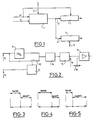
- FIG. 1 schematically illustrates the method according to the invention. Significant quantities of the zero sequence voltage on the busbar (vr) and of the zero sequence current on each feeder (ir) are used as input quantities.
- circuit 1 which is essentially constituted by a multiplier and which provides the instantaneous value of the zero sequence power for a wide frequency band, for frequencies ranging for example up to 3 kHz.
- Circuit 1 also includes at least one threshold circuit so that it provides at its output at least one threshold detection detection signal.
- One of these detection signals provides instantaneous signaling at 2; another detection signal provides at 3 a delayed fault signaling.
- Instantaneous signaling 2 is sent to an inhibition circuit 7 which provides an instantaneous fault signal at its output.
- the detection signal 3 corresponding to a permanent fault is sent to a timing circuit 4 which provides a delayed fault signal at its output.
- the inhibition circuit 7 is controlled by a signal supplied by the signal vr significant of the zero sequence voltage on the busbar.
- the threshold multiplier circuit 1 includes an inhibit input 5 by which it can receive an external inhibit signal fault detection.
- the timing circuit 4 can have a variable timing and it includes an input 6 for inhibiting the timing.
- the multiplier circuit 1 calculates the zero sequence energy or power in a minimum frequency bandwidth of 25 Hz to 1 Khz; this means that the energy conveyed by the zero sequence voltage and current signals in this frequency band must be taken into account with the performances indicated below.
- the relationships between the residual voltage Vr and the active residual current Ira on the various types of network to be considered are as follows: 4000 ⁇ Vr Will ⁇ 30 ⁇ in 20 kv 2000 ⁇ vr will go ⁇ 15 ⁇ at protection input, for any MV voltage
- zero sequence current sensors having a different transformation ratio, for example 50/1, may allow these protections to be used on rural type networks with very low capacitance with a minimum active residual current, on frank faults greater than 10 AT.
- Continuous detection of downstream faults is carried out as follows.
- the residual active power which rises from the network to the source station exceeds a certain adjustable threshold SW of residual active power at medium voltage, the protection system must provide instant detection information.
- the SW threshold adjustment range is low, between 0.4 and 4 W; these values correspond, for a 20 kW network to 8 and 80 kW.
- the accuracy of the actual operating threshold with respect to the displayed value must be less than 15%.
- the percentage of protection clearance on the aforementioned threshold SW must be 85 to 95%.
- the active release power must remain below 95% of the active detection power.
- the rise time in transient mode, the rise time must be such that the operation of the protection must occur less than 100 ms after the start of the 20 ms period considered for the analysis; with regard to the steady state, the rise time must be such that any signal whose power exceeds the threshold SW defined above for more than 60 ms must cause the protection to rise for at least 100 ms.
- the fall-back time of the protection must be between 220 and 260 ms.
- the protection must remain mounted for a time between 220 and 260 ms.
- the muting circuit operates as follows. When an earth fault occurs in the network, the healthy feeders are traversed by their capacitive currents. When the fault disappears, the zero sequence capacity of the healthy feeders discharges into the neutral impedance with an aperiodic or oscillatory regime damped according to the value of the neutral impedance.
- instantaneous outputs are inhibited.
- the total duration of the inhibition can for example be set to 400 ms.
- the inhibition circuit does not act on the timed signals.
- the timing circuit operates as follows. If circuit 1 provides detection information for a duration greater than the displayed time delay, which may for example be between 0.3 and 3 seconds, time delay circuit 4 provides time delayed fault signals. The accuracy of the time delay value with respect to the display must be less than 20 ms or 5% of the displayed value.
- the release time of timer circuit 4 from the fallout of instant fault information must be less than 20 ms.
- the delay recovery time for circuit 4 must also be less than 20 ms.
- the device described in FIG. 1 also includes possibilities for controlling external inhibition.
- the first inhibition input which acts on input 5 of circuit 1 inhibits the operation of circuit 1, which instantly drops the detection output signal. It is also possible to provide an external inhibition of the timer which acts on input 6 of circuit 4. When this input is activated, the response time of the timer circuit becomes less than 20 ms.
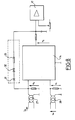
- FIG. 2 schematically represents a multiplier circuit which makes it possible to calculate in a wide frequency band the value of the zero sequence power.
- the voltages V1 and V2 respectively represent a voltage proportional to the zero sequence voltage on the busbar and a voltage proportional to the homopolar current.
- the voltage V2 is sent to a circuit 11 which outputs a signal equal to - V2 2 .
- the voltage V2 is also applied to an analog switch 12 which is controlled by an astable oscillator 13 which is controlled by the voltage V1.
- the output signals of circuit 11 and of switch 12 are sent to a summing circuit 14, the output of which is filtered by a low-pass filter 15.
- the voltage obtained V3 is compared with a threshold provided by a potentiometer 16 in a threshold comparator 17.
- the switch 12 beats at a high frequency which is higher than the frequency band in which it is desired to determine the zero sequence power. In other words, this frequency is large compared to the highest frequency contained in the signals V1 and V2.
- the flapping of the switch 12 takes place according to a form factor which is a function of the signal V1 by means of the astable oscillator 13.
- the opening time and the closing time of the switch 12 are equal to 1/2 or 50% as shown in FIG. 3.
- the closing time is greater than the opening time as shown in Figure 4 and when V1 is negative it is the closing time which is less than the opening time.
- the signal supplied by the switch 12 can be represented as in FIG. 6 where T is the period of the switch 12.
- the filtering circuit 15 makes it possible to extract the average value of the chopped signal supplied by the switch 12 so as to eliminate the component at frequency twice that of the network which results from the multiplication of the two signals V1 and V2.
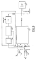
- Figure 7 is a more detailed diagram of the circuit shown in Figure 2.
- the value - V2 2 is supplied by an inverting amplifier 21 and the summing circuit and the filtering circuit are constituted by the operational amplifier 22, the resistors 23, 24 and 25 and the capacitor 26.
- the circuit of FIGS. 2 and 7 can be optimized by limiting the angular operating zone to the fundamental frequency by means of a feedback proportional to the absolute value of the current or to the reactive power. .
- FIG. 8 represents a circuit comprising a feedback from the zero sequence current.
- the feedback circuit is connected between the input and the output of the multiplier circuit 14 and it comprises in series a diode 31, a Zener diode 32 and a resistor 33.
- FIG. 9 represents an exemplary embodiment of a feedback from the reactive power Q.
- the reactive power is obtained from a second multiplier circuit 41 identical to the multiplier circuit 14 and receiving a signal V1 90 ° phase shifted by a phase shifter 42.
- the invention makes it possible to provide protection which functions very reliably and for all cases of network grounding.
- the device according to the invention is also suitable for fault detection on a low impedance earthing, for example 40 Ohms for a 20 kV network.
- the multiplier circuit has the advantage of being of simple structure; it can be made with low cost components.
Landscapes
- Emergency Protection Circuit Devices (AREA)
- Laying Of Electric Cables Or Lines Outside (AREA)
- Manufacturing Of Electrical Connectors (AREA)
Claims (7)
- Verfahren zum selektiven Schutz gegen Erdfehler in einer Verteilerstation eines elektrischen Netzes, das insbesondere für den Schutz der Quellenstationen an den Mittelspannungsausspeisungen bestimmt ist, dadurch gekennzeichnet, daß:- ständig an jeder Ausspeisung die Null-Momentanleistung auf einem breiten Frequenzband gemessen wird;- der gemessene Wert mit einem ersten Schwellenwert (SW) verglichen wird, und bei Überschreitung während einer einstellbaren Verzögerungszeit eine ständige Fehlermeldung erzeugt wird;- der gemessene Wert mit einem zweiten Schwellenwert (E), der größer ist als der erste, verglichen wird, und bei Überschreitung während einer Zeitdauer, die gleich einer Spannungsperiode ist, eine vorübergehende Fehlermeldung erzeugt wird;- die Nullspannung gemessen wird, daß diese mit einem Schwellenwert verglichen wird, der kleiner als der Wert der Nominalspannung ist, und daß bei Überschreitung während einer vorbestimmten Zeitdauer, die vor der Überschreitung des vorgenannten zweiten Schwellenwertes (E) stattfindet, die Momentanmeldungen aller Ausspeisungen während einer einstellbaren Hemmungszeit gehemmt werden.
- Verfahren zum selektiven Schutz nach Anspruch 1, dadurch gekennzeichnet, daß der zweite Schwellenwert (E) mit dem ersten Schwellenwert (SW) in einem gegebenen Verhältnis, wie beispielsweise 0,2, und zeitlich homogen verbunden ist.
- Verfahren zum selektiven Schutz nach Anspruch 1, dadurch gekennzeichnet, daß die Restblindleistung gemessen wird, daß diese mit der Restwirkleistung verglichen wird, und daß die ständige Fehlermeldung nur dann quittiert wird, wenn die Restwirkleistung größer als ein Vielfaches der Restblindleistung ist.
- Verfahren zum selektiven Schutz nach Anspruch 3, dadurch gekennzeichnet, daß der Wert der Restwirkleistung mit einem Wert gleich 15 mal den Wert der Restblindleistung verglichen wird.
- Verfahren zum selektiven Schutz nach Anspruch 1, dadurch gekennzeichnet, daß die Hemmungszeit 400 ms beträgt.
- Verfahren zum selektiven Schutz nach Anspruch 1, dadurch gekennzeichnet, daß die Verzögerungszeit zwischen 0,3 und 3 Sekunden liegt.
- Verfahren zum selektiven Schutz nach Anspruch 1, dadurch gekennzeichnet, daß die Messung der Null-Momentanleistung bei einem Frequenzband bis zu 3 KHz durchgeführt wird.
Applications Claiming Priority (2)
| Application Number | Priority Date | Filing Date | Title |
|---|---|---|---|
| FR9206736 | 1992-06-03 | ||
| FR9206736A FR2692086B1 (fr) | 1992-06-03 | 1992-06-03 | Procede et dispositif de protection selective contre les defauts a la terre d'un reseau electrique. |
Publications (2)
| Publication Number | Publication Date |
|---|---|
| EP0573333A1 EP0573333A1 (de) | 1993-12-08 |
| EP0573333B1 true EP0573333B1 (de) | 1996-09-18 |
Family
ID=9430405
Family Applications (1)
| Application Number | Title | Priority Date | Filing Date |
|---|---|---|---|
| EP93401360A Expired - Lifetime EP0573333B1 (de) | 1992-06-03 | 1993-05-27 | Verfahren zum selektiven Schutz gegen Erdfehler in einem elektrischen Netz |
Country Status (6)
| Country | Link |
|---|---|
| EP (1) | EP0573333B1 (de) |
| AT (1) | ATE143189T1 (de) |
| DE (1) | DE69304798T2 (de) |
| DK (1) | DK0573333T3 (de) |
| ES (1) | ES2094502T3 (de) |
| FR (1) | FR2692086B1 (de) |
Families Citing this family (5)
| Publication number | Priority date | Publication date | Assignee | Title |
|---|---|---|---|---|
| FR2772132B1 (fr) * | 1997-12-08 | 2000-02-04 | Conception Realisation Dev Ele | Procede de detection directionnelle de defaut sur un reseau de distribution d'energie electrique |
| AT413769B (de) * | 2002-06-26 | 2006-05-15 | Adaptive Regelsysteme Gmbh | Verfahren zur bestimmung eines parameters eines elektrischen netzes |
| ES2535750T3 (es) * | 2012-12-06 | 2015-05-14 | Schneider Electric Industries Sas | Detección direccional de un defecto, particularmente en una red de neutro compensado o aislado |
| FR2999295B1 (fr) * | 2012-12-06 | 2014-11-21 | Schneider Electric Ind Sas | Detection directionnelle d'un defaut dans un reseau a neutre isole |
| CN114167158B (zh) * | 2021-10-13 | 2024-09-13 | 安徽先兆科技有限公司 | 一种常见用电器电气安全隐患智能识别方法及系统 |
Citations (1)
| Publication number | Priority date | Publication date | Assignee | Title |
|---|---|---|---|---|
| EP0389749A2 (de) * | 1989-03-31 | 1990-10-03 | Landis & Gyr Betriebs AG | Anordnung zum Messen einer elektrischen Leistung oder Energie |
Family Cites Families (8)
| Publication number | Priority date | Publication date | Assignee | Title |
|---|---|---|---|---|
| EP0075348B1 (de) * | 1981-09-22 | 1985-08-14 | BBC Aktiengesellschaft Brown, Boveri & Cie. | Verfahren und Einrichtung zur Fehlerbestimmung an elektrischen Leitungen nach dem Unterimpedanzprinzip |
| JPS58146864A (ja) * | 1982-02-24 | 1983-09-01 | Mitsubishi Electric Corp | 位相検出装置 |
| DE3626398A1 (de) * | 1986-08-04 | 1988-02-11 | Siemens Ag | Elektronischer ueberstromausloeser |
| DE3626400A1 (de) * | 1986-08-04 | 1988-02-11 | Siemens Ag | Anordnung zur schnellerkennung von kurzschluessen |
| SE459059B (sv) * | 1987-09-16 | 1989-05-29 | Asea Ab | Skydd foer hoegresistiva jordfel |
| US4825327A (en) * | 1987-11-12 | 1989-04-25 | General Electric Company | Negative and zero sequence directional overcurrent unit for AC power transmission line protection |
| US4821137A (en) * | 1987-11-12 | 1989-04-11 | General Electric Company | Positive sequence distance relay for AC power transmission line protection |
| US4825323A (en) * | 1987-11-12 | 1989-04-25 | General Electric Company | Out-of-step blocking unit |
-
1992
- 1992-06-03 FR FR9206736A patent/FR2692086B1/fr not_active Expired - Fee Related
-
1993
- 1993-05-27 DE DE69304798T patent/DE69304798T2/de not_active Expired - Fee Related
- 1993-05-27 EP EP93401360A patent/EP0573333B1/de not_active Expired - Lifetime
- 1993-05-27 DK DK93401360.8T patent/DK0573333T3/da active
- 1993-05-27 AT AT93401360T patent/ATE143189T1/de not_active IP Right Cessation
- 1993-05-27 ES ES93401360T patent/ES2094502T3/es not_active Expired - Lifetime
Patent Citations (1)
| Publication number | Priority date | Publication date | Assignee | Title |
|---|---|---|---|---|
| EP0389749A2 (de) * | 1989-03-31 | 1990-10-03 | Landis & Gyr Betriebs AG | Anordnung zum Messen einer elektrischen Leistung oder Energie |
Also Published As
| Publication number | Publication date |
|---|---|
| ATE143189T1 (de) | 1996-10-15 |
| DE69304798D1 (de) | 1996-10-24 |
| FR2692086B1 (fr) | 1995-10-06 |
| DK0573333T3 (da) | 1996-10-07 |
| FR2692086A1 (fr) | 1993-12-10 |
| DE69304798T2 (de) | 1997-02-20 |
| ES2094502T3 (es) | 1997-01-16 |
| EP0573333A1 (de) | 1993-12-08 |
Similar Documents
| Publication | Publication Date | Title |
|---|---|---|
| EP1890165B1 (de) | Verfahren zur Richtungserkennung eines Massefehlers und Vorrichtung zur Umsetzung dieses Verfahrens | |
| FR2936319A1 (fr) | Detection directionnelle d'un defaut a la terre par correlation lineaire | |
| EP0053069B1 (de) | Verfahren zur Richtungserkennung einer Störung in einem elektrischen Netz | |
| EP0573333B1 (de) | Verfahren zum selektiven Schutz gegen Erdfehler in einem elektrischen Netz | |
| EP3384592B1 (de) | Verfahren und vorrichtung zur erkennung von lichtbögen in einer fotovoltaikanlage | |
| EP0568471B1 (de) | Einrichtung zur Überwachung eines homopolaren Fehlers im Stromnetz | |
| EP0022834B1 (de) | Verbesserungen an kapazitiven spannungstransformatoren | |
| EP0592337B1 (de) | Elektronischer Auslöser mit Erdschutz | |
| EP3594699B1 (de) | Differentialschutzvorrichtung | |
| EP3384594B1 (de) | Verfahren und vorrichtung zur bewertung der von einem elektrischen bogen erzeugten energie in einer fotovoltaikvorrichtung | |
| CA2967155C (fr) | Procede de manoeuvre de charges capacitives et dispositif pour la mise en oeuvre du procede | |
| EP1290456A1 (de) | Verfahren zur detektion von widerstandsbehafteten fehlern | |
| EP0851553B1 (de) | Elektronischer Auslöser mit, in Reihe geschalten, einem nichtrekursivem und einem rekursivem Filter | |
| EP1083644B1 (de) | Lichtbogenstromsensitiver Erdfehlerschutz, Auslöser und Schutzschalter mit einer solchen Vorrichtung | |
| EP1357386B1 (de) | Vorrichtung und Verfahren zur Detektion von elektrischen Ladungen und elektrisches Gerät mit einer solchen Anordnung | |
| EP4089422B1 (de) | Vorrichtung und verfahren zur schätzung der isolationsimpedanz eines tt- oder tn-netzes | |
| FR2651889A1 (fr) | Reducteur capacitif de tension electronique. | |
| FR3021816A1 (fr) | Chargeur de batterie pour vehicule automobile electrique a moyens de compensation passive variables et procede de commande d'un tel chargeur | |
| EP0914700B1 (de) | Verfahren und vorrichtung zur aufrechterhaltung der elektrischen stromversorgung in einem elektrischen mehrphasigen energieverteilungsnetz | |
| EP3798648B1 (de) | Verfahren zur bestimmung der position einer fehlervorstufe in einem in betrieb befindlichen hochspannungskabel | |
| EP4184183A1 (de) | Erkennung des offenen oder geschlossenen zustandes eines leistungsschalters | |
| EP3438681A1 (de) | Verfahren und vorrichtung zum testen des elektrischen lichtbogenschutzes, und elektrisches gerät, das diese vorrichtung umfasst | |
| FR2713411A1 (fr) | Dispositif détecteur de défauts homopolaires sur un réseau de distribution électrique. | |
| FR2554597A1 (fr) | Procede et appareil de mesure d'un courant electrique alternatif |
Legal Events
| Date | Code | Title | Description |
|---|---|---|---|
| PUAI | Public reference made under article 153(3) epc to a published international application that has entered the european phase |
Free format text: ORIGINAL CODE: 0009012 |
|
| AK | Designated contracting states |
Kind code of ref document: A1 Designated state(s): AT CH DE DK ES FR GB IT LI NL PT SE |
|
| 17P | Request for examination filed |
Effective date: 19940331 |
|
| GRAG | Despatch of communication of intention to grant |
Free format text: ORIGINAL CODE: EPIDOS AGRA |
|
| GRAH | Despatch of communication of intention to grant a patent |
Free format text: ORIGINAL CODE: EPIDOS IGRA |
|
| 17Q | First examination report despatched |
Effective date: 19960202 |
|
| GRAH | Despatch of communication of intention to grant a patent |
Free format text: ORIGINAL CODE: EPIDOS IGRA |
|
| GRAA | (expected) grant |
Free format text: ORIGINAL CODE: 0009210 |
|
| AK | Designated contracting states |
Kind code of ref document: B1 Designated state(s): AT CH DE DK ES FR GB IT LI NL PT SE |
|
| REF | Corresponds to: |
Ref document number: 143189 Country of ref document: AT Date of ref document: 19961015 Kind code of ref document: T |
|
| REG | Reference to a national code |
Ref country code: DK Ref legal event code: T3 |
|
| ITF | It: translation for a ep patent filed | ||
| REF | Corresponds to: |
Ref document number: 69304798 Country of ref document: DE Date of ref document: 19961024 |
|
| GBT | Gb: translation of ep patent filed (gb section 77(6)(a)/1977) |
Effective date: 19961025 |
|
| SC4A | Pt: translation is available |
Free format text: 961003 AVAILABILITY OF NATIONAL TRANSLATION |
|
| REG | Reference to a national code |
Ref country code: ES Ref legal event code: FG2A Ref document number: 2094502 Country of ref document: ES Kind code of ref document: T3 |
|
| PLBE | No opposition filed within time limit |
Free format text: ORIGINAL CODE: 0009261 |
|
| STAA | Information on the status of an ep patent application or granted ep patent |
Free format text: STATUS: NO OPPOSITION FILED WITHIN TIME LIMIT |
|
| 26N | No opposition filed | ||
| PGFP | Annual fee paid to national office [announced via postgrant information from national office to epo] |
Ref country code: CH Payment date: 20010417 Year of fee payment: 9 Ref country code: NL Payment date: 20010417 Year of fee payment: 9 |
|
| PGFP | Annual fee paid to national office [announced via postgrant information from national office to epo] |
Ref country code: SE Payment date: 20010419 Year of fee payment: 9 Ref country code: AT Payment date: 20010419 Year of fee payment: 9 |
|
| PGFP | Annual fee paid to national office [announced via postgrant information from national office to epo] |
Ref country code: DE Payment date: 20010420 Year of fee payment: 9 Ref country code: DK Payment date: 20010420 Year of fee payment: 9 |
|
| PGFP | Annual fee paid to national office [announced via postgrant information from national office to epo] |
Ref country code: PT Payment date: 20010423 Year of fee payment: 9 |
|
| PGFP | Annual fee paid to national office [announced via postgrant information from national office to epo] |
Ref country code: FR Payment date: 20010425 Year of fee payment: 9 |
|
| PGFP | Annual fee paid to national office [announced via postgrant information from national office to epo] |
Ref country code: ES Payment date: 20010511 Year of fee payment: 9 |
|
| PGFP | Annual fee paid to national office [announced via postgrant information from national office to epo] |
Ref country code: GB Payment date: 20010522 Year of fee payment: 9 |
|
| REG | Reference to a national code |
Ref country code: GB Ref legal event code: IF02 |
|
| PG25 | Lapsed in a contracting state [announced via postgrant information from national office to epo] |
Ref country code: GB Free format text: LAPSE BECAUSE OF NON-PAYMENT OF DUE FEES Effective date: 20020527 Ref country code: AT Free format text: LAPSE BECAUSE OF NON-PAYMENT OF DUE FEES Effective date: 20020527 |
|
| PG25 | Lapsed in a contracting state [announced via postgrant information from national office to epo] |
Ref country code: SE Free format text: LAPSE BECAUSE OF NON-PAYMENT OF DUE FEES Effective date: 20020528 Ref country code: ES Free format text: LAPSE BECAUSE OF NON-PAYMENT OF DUE FEES Effective date: 20020528 |
|
| PG25 | Lapsed in a contracting state [announced via postgrant information from national office to epo] |
Ref country code: LI Free format text: LAPSE BECAUSE OF NON-PAYMENT OF DUE FEES Effective date: 20020531 Ref country code: DK Free format text: LAPSE BECAUSE OF NON-PAYMENT OF DUE FEES Effective date: 20020531 Ref country code: CH Free format text: LAPSE BECAUSE OF NON-PAYMENT OF DUE FEES Effective date: 20020531 |
|
| PG25 | Lapsed in a contracting state [announced via postgrant information from national office to epo] |
Ref country code: PT Free format text: LAPSE BECAUSE OF NON-PAYMENT OF DUE FEES Effective date: 20021130 |
|
| PG25 | Lapsed in a contracting state [announced via postgrant information from national office to epo] |
Ref country code: NL Free format text: LAPSE BECAUSE OF NON-PAYMENT OF DUE FEES Effective date: 20021201 |
|
| PG25 | Lapsed in a contracting state [announced via postgrant information from national office to epo] |
Ref country code: DE Free format text: LAPSE BECAUSE OF NON-PAYMENT OF DUE FEES Effective date: 20021203 |
|
| REG | Reference to a national code |
Ref country code: DK Ref legal event code: EBP |
|
| EUG | Se: european patent has lapsed | ||
| GBPC | Gb: european patent ceased through non-payment of renewal fee |
Effective date: 20020527 |
|
| REG | Reference to a national code |
Ref country code: CH Ref legal event code: PL |
|
| PG25 | Lapsed in a contracting state [announced via postgrant information from national office to epo] |
Ref country code: FR Free format text: LAPSE BECAUSE OF NON-PAYMENT OF DUE FEES Effective date: 20030131 |
|
| NLV4 | Nl: lapsed or anulled due to non-payment of the annual fee |
Effective date: 20021201 |
|
| REG | Reference to a national code |
Ref country code: FR Ref legal event code: ST Ref country code: PT Ref legal event code: MM4A Free format text: LAPSE DUE TO NON-PAYMENT OF FEES Effective date: 20021130 |
|
| REG | Reference to a national code |
Ref country code: ES Ref legal event code: FD2A Effective date: 20030611 |
|
| PG25 | Lapsed in a contracting state [announced via postgrant information from national office to epo] |
Ref country code: IT Free format text: LAPSE BECAUSE OF NON-PAYMENT OF DUE FEES;WARNING: LAPSES OF ITALIAN PATENTS WITH EFFECTIVE DATE BEFORE 2007 MAY HAVE OCCURRED AT ANY TIME BEFORE 2007. THE CORRECT EFFECTIVE DATE MAY BE DIFFERENT FROM THE ONE RECORDED. Effective date: 20050527 |