EP0573327A1 - Prefabricated, fluid-tight and heat-insulating wall structure for vessels for cryogenic fluids - Google Patents
Prefabricated, fluid-tight and heat-insulating wall structure for vessels for cryogenic fluids Download PDFInfo
- Publication number
- EP0573327A1 EP0573327A1 EP93401304A EP93401304A EP0573327A1 EP 0573327 A1 EP0573327 A1 EP 0573327A1 EP 93401304 A EP93401304 A EP 93401304A EP 93401304 A EP93401304 A EP 93401304A EP 0573327 A1 EP0573327 A1 EP 0573327A1
- Authority
- EP
- European Patent Office
- Prior art keywords
- external
- joint
- layer
- insulation
- structure according
- Prior art date
- Legal status (The legal status is an assumption and is not a legal conclusion. Google has not performed a legal analysis and makes no representation as to the accuracy of the status listed.)
- Granted
Links
Images

Classifications
-
- B—PERFORMING OPERATIONS; TRANSPORTING
- B63—SHIPS OR OTHER WATERBORNE VESSELS; RELATED EQUIPMENT
- B63B—SHIPS OR OTHER WATERBORNE VESSELS; EQUIPMENT FOR SHIPPING
- B63B25/00—Load-accommodating arrangements, e.g. stowing, trimming; Vessels characterised thereby
- B63B25/02—Load-accommodating arrangements, e.g. stowing, trimming; Vessels characterised thereby for bulk goods
- B63B25/08—Load-accommodating arrangements, e.g. stowing, trimming; Vessels characterised thereby for bulk goods fluid
- B63B25/12—Load-accommodating arrangements, e.g. stowing, trimming; Vessels characterised thereby for bulk goods fluid closed
- B63B25/16—Load-accommodating arrangements, e.g. stowing, trimming; Vessels characterised thereby for bulk goods fluid closed heat-insulated
-
- F—MECHANICAL ENGINEERING; LIGHTING; HEATING; WEAPONS; BLASTING
- F17—STORING OR DISTRIBUTING GASES OR LIQUIDS
- F17C—VESSELS FOR CONTAINING OR STORING COMPRESSED, LIQUEFIED OR SOLIDIFIED GASES; FIXED-CAPACITY GAS-HOLDERS; FILLING VESSELS WITH, OR DISCHARGING FROM VESSELS, COMPRESSED, LIQUEFIED, OR SOLIDIFIED GASES
- F17C3/00—Vessels not under pressure
- F17C3/02—Vessels not under pressure with provision for thermal insulation
- F17C3/025—Bulk storage in barges or on ships
-
- F—MECHANICAL ENGINEERING; LIGHTING; HEATING; WEAPONS; BLASTING
- F17—STORING OR DISTRIBUTING GASES OR LIQUIDS
- F17C—VESSELS FOR CONTAINING OR STORING COMPRESSED, LIQUEFIED OR SOLIDIFIED GASES; FIXED-CAPACITY GAS-HOLDERS; FILLING VESSELS WITH, OR DISCHARGING FROM VESSELS, COMPRESSED, LIQUEFIED, OR SOLIDIFIED GASES
- F17C3/00—Vessels not under pressure
- F17C3/02—Vessels not under pressure with provision for thermal insulation
- F17C3/04—Vessels not under pressure with provision for thermal insulation by insulating layers
-
- F—MECHANICAL ENGINEERING; LIGHTING; HEATING; WEAPONS; BLASTING
- F17—STORING OR DISTRIBUTING GASES OR LIQUIDS
- F17C—VESSELS FOR CONTAINING OR STORING COMPRESSED, LIQUEFIED OR SOLIDIFIED GASES; FIXED-CAPACITY GAS-HOLDERS; FILLING VESSELS WITH, OR DISCHARGING FROM VESSELS, COMPRESSED, LIQUEFIED, OR SOLIDIFIED GASES
- F17C2201/00—Vessel construction, in particular geometry, arrangement or size
- F17C2201/05—Size
- F17C2201/052—Size large (>1000 m3)
-
- F—MECHANICAL ENGINEERING; LIGHTING; HEATING; WEAPONS; BLASTING
- F17—STORING OR DISTRIBUTING GASES OR LIQUIDS
- F17C—VESSELS FOR CONTAINING OR STORING COMPRESSED, LIQUEFIED OR SOLIDIFIED GASES; FIXED-CAPACITY GAS-HOLDERS; FILLING VESSELS WITH, OR DISCHARGING FROM VESSELS, COMPRESSED, LIQUEFIED, OR SOLIDIFIED GASES
- F17C2203/00—Vessel construction, in particular walls or details thereof
- F17C2203/01—Reinforcing or suspension means
- F17C2203/011—Reinforcing means
- F17C2203/012—Reinforcing means on or in the wall, e.g. ribs
-
- F—MECHANICAL ENGINEERING; LIGHTING; HEATING; WEAPONS; BLASTING
- F17—STORING OR DISTRIBUTING GASES OR LIQUIDS
- F17C—VESSELS FOR CONTAINING OR STORING COMPRESSED, LIQUEFIED OR SOLIDIFIED GASES; FIXED-CAPACITY GAS-HOLDERS; FILLING VESSELS WITH, OR DISCHARGING FROM VESSELS, COMPRESSED, LIQUEFIED, OR SOLIDIFIED GASES
- F17C2203/00—Vessel construction, in particular walls or details thereof
- F17C2203/03—Thermal insulations
- F17C2203/0304—Thermal insulations by solid means
- F17C2203/0329—Foam
- F17C2203/0333—Polyurethane
-
- F—MECHANICAL ENGINEERING; LIGHTING; HEATING; WEAPONS; BLASTING
- F17—STORING OR DISTRIBUTING GASES OR LIQUIDS
- F17C—VESSELS FOR CONTAINING OR STORING COMPRESSED, LIQUEFIED OR SOLIDIFIED GASES; FIXED-CAPACITY GAS-HOLDERS; FILLING VESSELS WITH, OR DISCHARGING FROM VESSELS, COMPRESSED, LIQUEFIED, OR SOLIDIFIED GASES
- F17C2203/00—Vessel construction, in particular walls or details thereof
- F17C2203/03—Thermal insulations
- F17C2203/0304—Thermal insulations by solid means
- F17C2203/0354—Wood
-
- F—MECHANICAL ENGINEERING; LIGHTING; HEATING; WEAPONS; BLASTING
- F17—STORING OR DISTRIBUTING GASES OR LIQUIDS
- F17C—VESSELS FOR CONTAINING OR STORING COMPRESSED, LIQUEFIED OR SOLIDIFIED GASES; FIXED-CAPACITY GAS-HOLDERS; FILLING VESSELS WITH, OR DISCHARGING FROM VESSELS, COMPRESSED, LIQUEFIED, OR SOLIDIFIED GASES
- F17C2203/00—Vessel construction, in particular walls or details thereof
- F17C2203/03—Thermal insulations
- F17C2203/0304—Thermal insulations by solid means
- F17C2203/0358—Thermal insulations by solid means in form of panels
-
- F—MECHANICAL ENGINEERING; LIGHTING; HEATING; WEAPONS; BLASTING
- F17—STORING OR DISTRIBUTING GASES OR LIQUIDS
- F17C—VESSELS FOR CONTAINING OR STORING COMPRESSED, LIQUEFIED OR SOLIDIFIED GASES; FIXED-CAPACITY GAS-HOLDERS; FILLING VESSELS WITH, OR DISCHARGING FROM VESSELS, COMPRESSED, LIQUEFIED, OR SOLIDIFIED GASES
- F17C2203/00—Vessel construction, in particular walls or details thereof
- F17C2203/06—Materials for walls or layers thereof; Properties or structures of walls or their materials
- F17C2203/0634—Materials for walls or layers thereof
- F17C2203/0636—Metals
- F17C2203/0639—Steels
- F17C2203/0643—Stainless steels
-
- F—MECHANICAL ENGINEERING; LIGHTING; HEATING; WEAPONS; BLASTING
- F17—STORING OR DISTRIBUTING GASES OR LIQUIDS
- F17C—VESSELS FOR CONTAINING OR STORING COMPRESSED, LIQUEFIED OR SOLIDIFIED GASES; FIXED-CAPACITY GAS-HOLDERS; FILLING VESSELS WITH, OR DISCHARGING FROM VESSELS, COMPRESSED, LIQUEFIED, OR SOLIDIFIED GASES
- F17C2203/00—Vessel construction, in particular walls or details thereof
- F17C2203/06—Materials for walls or layers thereof; Properties or structures of walls or their materials
- F17C2203/0634—Materials for walls or layers thereof
- F17C2203/0636—Metals
- F17C2203/0646—Aluminium
-
- F—MECHANICAL ENGINEERING; LIGHTING; HEATING; WEAPONS; BLASTING
- F17—STORING OR DISTRIBUTING GASES OR LIQUIDS
- F17C—VESSELS FOR CONTAINING OR STORING COMPRESSED, LIQUEFIED OR SOLIDIFIED GASES; FIXED-CAPACITY GAS-HOLDERS; FILLING VESSELS WITH, OR DISCHARGING FROM VESSELS, COMPRESSED, LIQUEFIED, OR SOLIDIFIED GASES
- F17C2203/00—Vessel construction, in particular walls or details thereof
- F17C2203/06—Materials for walls or layers thereof; Properties or structures of walls or their materials
- F17C2203/0634—Materials for walls or layers thereof
- F17C2203/0658—Synthetics
- F17C2203/066—Plastics
-
- F—MECHANICAL ENGINEERING; LIGHTING; HEATING; WEAPONS; BLASTING
- F17—STORING OR DISTRIBUTING GASES OR LIQUIDS
- F17C—VESSELS FOR CONTAINING OR STORING COMPRESSED, LIQUEFIED OR SOLIDIFIED GASES; FIXED-CAPACITY GAS-HOLDERS; FILLING VESSELS WITH, OR DISCHARGING FROM VESSELS, COMPRESSED, LIQUEFIED, OR SOLIDIFIED GASES
- F17C2203/00—Vessel construction, in particular walls or details thereof
- F17C2203/06—Materials for walls or layers thereof; Properties or structures of walls or their materials
- F17C2203/0634—Materials for walls or layers thereof
- F17C2203/0658—Synthetics
- F17C2203/0663—Synthetics in form of fibers or filaments
-
- F—MECHANICAL ENGINEERING; LIGHTING; HEATING; WEAPONS; BLASTING
- F17—STORING OR DISTRIBUTING GASES OR LIQUIDS
- F17C—VESSELS FOR CONTAINING OR STORING COMPRESSED, LIQUEFIED OR SOLIDIFIED GASES; FIXED-CAPACITY GAS-HOLDERS; FILLING VESSELS WITH, OR DISCHARGING FROM VESSELS, COMPRESSED, LIQUEFIED, OR SOLIDIFIED GASES
- F17C2205/00—Vessel construction, in particular mounting arrangements, attachments or identifications means
- F17C2205/01—Mounting arrangements
- F17C2205/0153—Details of mounting arrangements
- F17C2205/0184—Attachments to the ground, e.g. mooring or anchoring
-
- F—MECHANICAL ENGINEERING; LIGHTING; HEATING; WEAPONS; BLASTING
- F17—STORING OR DISTRIBUTING GASES OR LIQUIDS
- F17C—VESSELS FOR CONTAINING OR STORING COMPRESSED, LIQUEFIED OR SOLIDIFIED GASES; FIXED-CAPACITY GAS-HOLDERS; FILLING VESSELS WITH, OR DISCHARGING FROM VESSELS, COMPRESSED, LIQUEFIED, OR SOLIDIFIED GASES
- F17C2223/00—Handled fluid before transfer, i.e. state of fluid when stored in the vessel or before transfer from the vessel
- F17C2223/01—Handled fluid before transfer, i.e. state of fluid when stored in the vessel or before transfer from the vessel characterised by the phase
- F17C2223/0146—Two-phase
- F17C2223/0153—Liquefied gas, e.g. LPG, GPL
- F17C2223/0161—Liquefied gas, e.g. LPG, GPL cryogenic, e.g. LNG, GNL, PLNG
-
- F—MECHANICAL ENGINEERING; LIGHTING; HEATING; WEAPONS; BLASTING
- F17—STORING OR DISTRIBUTING GASES OR LIQUIDS
- F17C—VESSELS FOR CONTAINING OR STORING COMPRESSED, LIQUEFIED OR SOLIDIFIED GASES; FIXED-CAPACITY GAS-HOLDERS; FILLING VESSELS WITH, OR DISCHARGING FROM VESSELS, COMPRESSED, LIQUEFIED, OR SOLIDIFIED GASES
- F17C2223/00—Handled fluid before transfer, i.e. state of fluid when stored in the vessel or before transfer from the vessel
- F17C2223/03—Handled fluid before transfer, i.e. state of fluid when stored in the vessel or before transfer from the vessel characterised by the pressure level
- F17C2223/033—Small pressure, e.g. for liquefied gas
-
- F—MECHANICAL ENGINEERING; LIGHTING; HEATING; WEAPONS; BLASTING
- F17—STORING OR DISTRIBUTING GASES OR LIQUIDS
- F17C—VESSELS FOR CONTAINING OR STORING COMPRESSED, LIQUEFIED OR SOLIDIFIED GASES; FIXED-CAPACITY GAS-HOLDERS; FILLING VESSELS WITH, OR DISCHARGING FROM VESSELS, COMPRESSED, LIQUEFIED, OR SOLIDIFIED GASES
- F17C2260/00—Purposes of gas storage and gas handling
- F17C2260/03—Dealing with losses
- F17C2260/031—Dealing with losses due to heat transfer
- F17C2260/033—Dealing with losses due to heat transfer by enhancing insulation
-
- F—MECHANICAL ENGINEERING; LIGHTING; HEATING; WEAPONS; BLASTING
- F17—STORING OR DISTRIBUTING GASES OR LIQUIDS
- F17C—VESSELS FOR CONTAINING OR STORING COMPRESSED, LIQUEFIED OR SOLIDIFIED GASES; FIXED-CAPACITY GAS-HOLDERS; FILLING VESSELS WITH, OR DISCHARGING FROM VESSELS, COMPRESSED, LIQUEFIED, OR SOLIDIFIED GASES
- F17C2260/00—Purposes of gas storage and gas handling
- F17C2260/03—Dealing with losses
- F17C2260/035—Dealing with losses of fluid
- F17C2260/036—Avoiding leaks
-
- F—MECHANICAL ENGINEERING; LIGHTING; HEATING; WEAPONS; BLASTING
- F17—STORING OR DISTRIBUTING GASES OR LIQUIDS
- F17C—VESSELS FOR CONTAINING OR STORING COMPRESSED, LIQUEFIED OR SOLIDIFIED GASES; FIXED-CAPACITY GAS-HOLDERS; FILLING VESSELS WITH, OR DISCHARGING FROM VESSELS, COMPRESSED, LIQUEFIED, OR SOLIDIFIED GASES
- F17C2270/00—Applications
- F17C2270/01—Applications for fluid transport or storage
- F17C2270/0102—Applications for fluid transport or storage on or in the water
- F17C2270/0105—Ships
- F17C2270/0107—Wall panels
-
- Y—GENERAL TAGGING OF NEW TECHNOLOGICAL DEVELOPMENTS; GENERAL TAGGING OF CROSS-SECTIONAL TECHNOLOGIES SPANNING OVER SEVERAL SECTIONS OF THE IPC; TECHNICAL SUBJECTS COVERED BY FORMER USPC CROSS-REFERENCE ART COLLECTIONS [XRACs] AND DIGESTS
- Y10—TECHNICAL SUBJECTS COVERED BY FORMER USPC
- Y10S—TECHNICAL SUBJECTS COVERED BY FORMER USPC CROSS-REFERENCE ART COLLECTIONS [XRACs] AND DIGESTS
- Y10S220/00—Receptacles
- Y10S220/901—Liquified gas content, cryogenic
Definitions
- the present invention relates to a prefabricated structure making it possible to produce leaktight and thermally insulating walls for a thermally insulated confinement enclosure, such as a sealed reservoir for storing and / or transporting a fluid at very low temperature, such as by example a liquefied gas or a cryogenic liquid.
- This structure of the prior art can be mounted in the hold or double-hold of a merchant ship, whose rigid self-supporting partitions form an external support for the other elements of the structure.
- An internal or primary waterproof barrier which defines a substantially deformable hermetic tank and designed to contain the fluid, is assembled from elements generally made of metal inside the space defined by the external partitions of the support.
- a thermal insulation system is interposed between the external partitions and the primary barrier.
- This insulation system comprises at least two layers of insulating and waterproof material such as plastic foam with closed cells, formed by juxtaposition of prefabricated plates.
- the two layers of insulation are sandwiched by two load distribution panels inside the structure, for example in plywood.
- a panel secured to the external partition is glued to a so-called “external” insulation layer, while the other panel which is secured to the internal barrier is glued to another so-called “internal” layer.
- buffers made of the same type of material as the insulation plates are placed in the joints between the juxtaposed plates of the outer layer and are respectively covered with a strip hermetically bonded to the outer layer and generally comprising a central sheet of waterproof aluminum as well as two layers of fiberglass fabric.
- the present invention aims to overcome the above drawbacks, by proposing a simple and economical structure in which the insulation layers are continuous and therefore perfectly sealed.
- the subject of the invention is a prefabricated structure for forming leaktight and thermally insulating walls for the production of a heat-insulated enclosure for confining a fluid at very low temperature such as a liquefied gas, and of the type comprising a substantially flexible internal or primary waterproof barrier to which an internal distribution panel is attached, a rigid external partition forming a support for the structure and to which another said external panel is attached as well as two intermediate layers of thermal insulation sandwiched between the distribution panels and respectively said internal and external, each layer which is produced by juxtaposition of insulating plates of waterproof material such as for example a closed cell plastic foam, defines joints between the plates respectively disposed opposite a plate of the other layer, each joint of the outer insulation layer being covered rte by a strip glued between the two layers of insulation, characterized in that the external distribution panels are fixed to the external partition in particular by screws or the like, arranged opposite holes formed in the external layer at a distance from the joints, and a sealed connection made of insulating material fills and adheres hermet
- the covering strip is formed by a continuous reinforcing sheet of glass fiber or the like, which extends over a surface substantially greater than that of the plate juxtaposed with the internal insulation layer. , opposite the joint to be covered and preferably over the entire surface of the corresponding wall formed by the structure.
- At least one of the aforementioned connections is an insert of shape corresponding to that of the joint or of the hole to be filled, of which at least the external peripheral surface is coated with an adhesive material, preferably foaming.
- connection is constituted by two elements which are substantially symmetrical with respect to a median plane of assembly, and whose internal surfaces of assembly facing each other are coated with adhesive material.
- the invention is also characterized in that at least one of the aforementioned connections is formed in situ by pressure injection of the aforementioned waterproof insulation plastic material inside the hole or the joint to be filled.
- the material forming the aforementioned fittings is injected by means of a tool bearing against the surface of the external layer of insulation opposite the external partition, and fixed to the latter facing the opening of the hole. or the join to be completed.
- a pad made of waterproof material to which the aforementioned connection of a joint adheres hermetically is interposed between the reinforcement panel and the external partition.
- the structure 1 is a reservoir constituted by an assembly of sealed and heat-insulated walls, in which a cryogenic liquid such as a very cold liquefied gas, such as in particular methane, can be stored.
- a cryogenic liquid such as a very cold liquefied gas, such as in particular methane
- the structure 1 comprises a sealed internal envelope capable of containing the fluid to be stored, which is composed by assembling prefabricated elements forming jointly for each wall of the structure 1, an internal or primary waterproof barrier 2.
- the barrier Primary 2 is formed by thin metal elements such as stainless steel or aluminum sheet.
- the reference numeral 2a designates ribs projecting parallel to the connections 2b between the different elements of the barrier 2, which allow the envelope formed by this barrier to be substantially flexible, in order to be able to deform under the effect of the stresses, notably thermal generated by the fluid stored therein.
- a rigid external partition 3 of the structure 1 acts as a support for the latter.
- this partition 3 is a self-supporting metal sheet of hold or of double hold of a merchant ship, such as an LNG carrier.
- a merchant ship such as an LNG carrier.
- other types of rigid partitions whose mechanical properties are appropriate, such as in particular a concrete wall in a firm ground construction, could be used as external partition supporting the structure 1.
- a thermal insulation system generally designated at 4 is provided between the primary barrier 2 and the external partition 3.
- the insulation or insulation system 4 of the structure 1 notably includes an internal insulation layer 42 to which is linked primary barrier 2, as well as an external insulation layer 43 secured to the external support partition 3.
- the outer and inner layers 42, 43 are made from a waterproof thermal insulation material.
- a plastic or synthetic foam with closed cells use a plastic or synthetic foam with closed cells.
- a closed cell foam based on polyurethane or polyvinyl chloride in particular may be perfectly suitable for the production of these insulation layers 42,43.
- FIG. 1 it can be seen that the two insulation layers 42, 43 are sandwiched or sandwiched between two force distribution panels 52 and 53.
- These panels 52, 53 respectively internal and external, are for example made from of assembled pieces of plywood or laminate.
- the internal and external panels 52 and 53 make it possible to distribute almost uniformly in the structure and in particular the insulation system 4, the forces for example linked to deformations of the external partition 3 and of the envelope defined by the internal barrier 2
- the panel 52 is supported, and preferably glued to the upper surface (that is to say the one closest to the barrier 2) of the insulation layer 42, while the outer panel 53 is in abutment, and preferably glued to the lower surface (namely facing with the partition 3) of the insulation layer 43.
- each insulation layer 42, 43 is formed by juxtaposition of insulating plates made of waterproof material, designated at 42a or 43a, respectively, and whose shape is generally prismatic rectangular. It goes without saying that in the corner or edge parts of the structure 1, the insulating plates 42a or 43a may be bevelled at an angle appropriate to that formed by the structure 1 at this edge, in order to form the largest possible joins. In addition, the plates 42a, 43a will be prefabricated with standard dimensions, which obviously can be modified by cutting according to the shape of the structure to be produced.
- the insulating plates 42a, 43a are arranged end-to-end so as to define in each layer 42, 43 generally linear joints 62, 63 respectively. These joints 62, 63 generally extend along a direction plane perpendicular to the median plane of the panels 52, 53, over at least the entire thickness of the corresponding insulation layer 42, 43.
- Each of the joints 63 formed in the layer outer is covered by a strip 70 which is interposed and glued between the two layers of insulating foam 42 and 43 and comes in line with a plate 42a of the inner layer 42.
- the distribution panels 53 are fixed to the external partition 3, in particular by screws or the like 35, visible in FIG. 5.
- These screws 35 shown in the other figures only by their longitudinal axis, are arranged in hole look 435, themselves formed in the outer insulation layer 43, at a distance from the joints 63 between the different juxtaposed plates 43a constituting this layer.
- each of the joints 63 and all the holes 435 in question are filled by a fitting 80 made of thermally insulating and waterproof material.
- These insulating and leaktight connections 80 may in particular be made of the same material or of a material similar to that of the insulation layers 42 and 43, for example ethyl vinyl acetate.
- all the fittings 80 arranged in the joints 63 and in the holes 435 of the layer 43 are bonded to adhere tightly to the walls of the hole 435 or of the corresponding joint 63, in order to make the outer layer 43 continuous and tight over all the area defined by structure 1.
- the secondary seal is obtained by making the plates 43a and fittings 80 hermetically integral, so that the prefabricated layer of external insulation 43 forms, after its assembly and bonding, a barrier secondary continuous and therefore perfectly waterproof.
- joints 62 between the plates 42a of the internal insulation layer will preferably also be hermetically sealed by flexible joints (possibly glued) in liquid mastic polymerized by example.
- the secondary barrier is formed by the entire insulation system 4.
- each covering strip 70 must extend widely beyond the surface of the external layer 43 where the holes 435 and the joint 63 to be covered are formed.
- each reinforcing strip 70 will be chosen so that it is substantially equal to that of the corresponding external plate 42a. It is advantageous if the imperatives of assembly of the prefabricated elements of the structure 1 allow it, to completely cover the external layer of insulation 43 with a reinforcing fabric on which the reinforcing strips 70 may be glued.
- the fittings 80 provided for filling the holes 435 as well as the joints 63 illustrated are constituted by inserts of shape corresponding to that orifices (63, 435) to be filled in the layer 43.
- the connection intended to be housed in the direction of the arrow F1 in the joint 63 and designated at 83 is a tight flat seal.
- This joint in the form of a flat joint 83 has a length in the direction of the arrow F1 which is substantially equal to the thickness of the assembly formed by the layer 43 and the panels 53.
- a pad 33 preferably made of a waterproof flexible plastic foam is interposed between the panels 53 arranged on either side of the joint 63, and the external partition 3.
- This pad 33 the section along a transverse plane perpendicular to the median plane P of the joint 63 is trapezoidal, rests by one of its parallel faces whose surface is the smallest, against the internal face of the partition 3. Furthermore, the longitudinal edges of its most important parallel face are respectively in abutment against the external face opposite the partition 3 of one of the panels 53 contiguous to the joint 63.
- each connector 80 is coated with a layer of suitable glue, preferably a foaming glue.
- suitable glue preferably a foaming glue.
- each element will be symmetrical to the other along a plane coincident with the (or one) of the median planes of the orifice 63 or 435 to be filled using this connection in several elements.
- the fitting 83 could be formed by assembling two elements symmetrical with respect to the median plane P. The faces of these elements constituting the fitting 83 which extend along the plane P are coated with an appropriate adhesive, preferably foaming , and assembled just before mounting and gluing the fitting thus formed in the joint 63.
- an empty space 56 is provided in the joint 63 between the insulation layer 43 and the metal shim 36 located on the side opposite the corner defined by the structure 1.
- fittings 85 shown in FIG. 5 and intended to fill the holes 435 are in the form of cylindrical studs or logs of shape corresponding to that of each hole. Their end faces coming opposite the corresponding panel 53 are hollowed out at their center, so that the screw 35 protruding into this hole 435 can be accommodated there.
- connection 85 an annular end surface is provided which can be brought into contact with the panel 53 constituting the bottom of the hole 435, and be hermetically bonded to this panel around the screw 35 Likewise, the cylindrical walls of the connector 85 are coated with suitable adhesive, preferably foaming, so that the latter forms, after setting the adhesive, a single sealed part with the insulating plate 43a inside which it is housed.
- suitable adhesive preferably foaming
- the cylindrical insert 85 can also be obtained by assembling and bonding two elements, for example made of closed-cell polyurethane foam.
- connection filling the joint 63 between the two juxtaposed insulation plates 43a is obtained in situ. More specifically, the bottom of the joint 63 is hermetically sealed by a buffer 33 generally identical to that which has been described above.
- An injection tool 100 is fixed to the insulation system 4, in order to close off the opening part of the joint 63.
- the injection tool 100 is composed of a plate 103 capable of coming to hermetically bear against the face top of the insulation layer 43 by covering the joint 63, and by at least two extension studs 135 provided for fixing on the screws 35.
- the plate 103 of the tool 100 can be pressed tightly against the outer insulation layer 43, so that the interior space defined by the joint 63 is hermetically sealed.
- the plate 103 of the tool 100 comprises an injection mouth 160 associated with at least one vent which makes it possible to put the interior of the joint 63 into communication with a source S of insulating and waterproof plastic material capable of expand, such as preferably closed cell polyurethane.
- the plastic material of the source S is injected under an appropriate pressure into the space defined by the joint 63, in order to fill it completely.
- the injected expandable material designated here at 84 is dried and it adheres hermetically to the walls of the joint 63 and of the pad 33, a connection 80 has been obtained.
- the material 84 of the connection 80 and the two plates of insulating material 43a juxtaposed to the corresponding connection 63 no longer form a single continuous part, and consequently cannot in any case allow a fluid to pass.
- the holes 435 provided for access to the assembly or fixing screws 35 can also be filled by injection of an expandable waterproof material such as that designated at 84.
- the material 84 can fill the joint 63 up to the flower of the outer layer of insulation 43, so that the plates 43a will be connected in a manner continues through the fitting 80 thus produced, and it will be easy to apply to a surface thus formed a reinforcing strip 70.
- the injection pressure of the material 84 as well as the force necessary to accommodate the fittings 80 constituted by attached parts such as those which are illustrated in FIG. 5, will be chosen so that in the final position of these fittings 80 and juxtaposed plates 43a, the stresses generated by these fittings 80 inside the outer layer 43 are of negligible value, in particular with respect to the cohesive force exerted by the adhesives (including by the injected material 84) as well only by the covering strips 70 which connect the fittings 80 and the plates 43a.
- the load distribution panel 52 is replaced by a metal angle.
- the metal angle is made up of elements 52a of stainless metal such as treated steel or aluminum, which are juxtaposed and assembled using screws 45 ( Figure 1) which are fixed in the material of the plates 42a constituting the internal insulation layer 42 of the system 4.
- a flexible joint 62a such as that described with reference to FIG. 1, can be interposed between the elements 42a so as to adhere to them .
- FIG. 2 shows a planar structure 1 made up of prefabricated elements assembled in accordance with the invention.
- the panel 52 consists of elements fixed to the corresponding insulation plates 42a by collage.
- Metallic inserts 142 can be provided on such a panel 52 for fixing tools in particular.
- Strips of stainless metal 166 which extend transversely to each of the elements of the panel 52 are respectively crimped in suitable housings arranged in alignment and formed in the elements which constitute this panel by juxtaposition.
- a structure 1 was therefore obtained in accordance with the invention which, in the event of a leakage through the primary barrier 2 makes it possible to ensure that the thermal gradient in the insulation system 4 is not affected.
- the layer 70 has only a mechanical function, it is no longer necessary to provide a sealed metal sheet sandwiched at the level of the strips and of the covering sheet.
- the invention makes it possible to significantly reduce the costs of manufacturing tanks for cryogenic liquids in, for example, commercial ships, while guaranteeing a higher quality of insulation and sealing than could be obtained in the prior art.
- the displacement of the secondary sealing makes it possible to use a less expensive grade of steel for the external partition. of support.
Landscapes
- Engineering & Computer Science (AREA)
- Mechanical Engineering (AREA)
- Physics & Mathematics (AREA)
- Thermal Sciences (AREA)
- General Engineering & Computer Science (AREA)
- Chemical & Material Sciences (AREA)
- Combustion & Propulsion (AREA)
- Ocean & Marine Engineering (AREA)
- Filling Or Discharging Of Gas Storage Vessels (AREA)
Abstract
Description
La présente invention se rapporte à une structure préfabriquée permettant de réaliser des parois étanches et thermiquement isolantes pour une enceinte de confinement calorifugée, telle qu'un réservoir étanche d'emmagasinage et/ou de transport d'un fluide à très basse température, comme par exemple un gaz liquéfié ou un liquide cryogénique.The present invention relates to a prefabricated structure making it possible to produce leaktight and thermally insulating walls for a thermally insulated confinement enclosure, such as a sealed reservoir for storing and / or transporting a fluid at very low temperature, such as by example a liquefied gas or a cryogenic liquid.
On a déjà décrit, notamment dans le document FR-A-2 599 468 au nom de la demanderesse, une structure constituée par des éléments préfabriqués assemblés de façon à obtenir une enceinte calorifugée hermétique pouvant contenir par exemple du méthane liquéfié. Cette structure de l'art antérieur peut être montée dans la cale ou double-cale d'un navire marchand, dont les cloisons rigides auto-portantes forment un support externe pour les autres éléments de la structure. Une barrière étanche interne ou primaire, qui définit une cuve hermétique sensiblement déformable et prévue pour contenir le fluide, est assemblée à partir d'éléments généralement en métal à l'intérieur de l'espace défini par les cloisons externes du support. Un système d'isolation thermique est interposé entre les cloisons externes et la barrière primaire. Ce système d'isolation comprend au moins deux couches en matière isolante et étanche telle que mousse plastique à cellules fermées, formées par juxtaposition de plaques préfabriquées. Les deux couches d'isolation sont prises en sandwich par deux panneaux de répartition des efforts à l'intérieur de la structure, par exemple en bois contre-plaqué. Un panneau solidaire de la cloison externe est collé à une couche d'isolation dite "externe", tandis que l'autre panneau qui est solidaire de la barrière interne est collé à une autre couche dite "interne". Pour maintenir l'étanchéité de la structure en cas de fissuration de la barrière primaire, des tampons réalisés dans le même type de matériau que les plaques d'isolation sont disposés dans les jointures entre les plaques juxtaposées de la couche externe puis sont respectivement recouverts avec une bande collée hermétiquement sur la couche externe et comprenant généralement une feuille centrale en aluminium étanche ainsi que deux couches de tissu en fibre de verre.We have already described, in particular in document FR-A-2 599 468 in the name of the applicant, a structure constituted by prefabricated elements assembled so as to obtain a hermetic heat-insulated enclosure which may contain, for example, liquefied methane. This structure of the prior art can be mounted in the hold or double-hold of a merchant ship, whose rigid self-supporting partitions form an external support for the other elements of the structure. An internal or primary waterproof barrier, which defines a substantially deformable hermetic tank and designed to contain the fluid, is assembled from elements generally made of metal inside the space defined by the external partitions of the support. A thermal insulation system is interposed between the external partitions and the primary barrier. This insulation system comprises at least two layers of insulating and waterproof material such as plastic foam with closed cells, formed by juxtaposition of prefabricated plates. The two layers of insulation are sandwiched by two load distribution panels inside the structure, for example in plywood. A panel secured to the external partition is glued to a so-called "external" insulation layer, while the other panel which is secured to the internal barrier is glued to another so-called "internal" layer. To maintain the watertightness of the structure in the event of cracking of the primary barrier, buffers made of the same type of material as the insulation plates are placed in the joints between the juxtaposed plates of the outer layer and are respectively covered with a strip hermetically bonded to the outer layer and generally comprising a central sheet of waterproof aluminum as well as two layers of fiberglass fabric.
Toutefois, dans les structures connues au niveau des jointures, seule la bande de recouvrement assure l'étanchéité entre les couches d'isolation interne et externe. De fait, en cas de fuite à travers la barrière primaire, toute l'étanchéité repose sur cette bande, ce qui risque de générer un refroidissement si l'une de ces bandes de recouvrement venait à ne plus être hermétique.However, in the known structures at the joints, only the covering strip provides sealing between the layers of internal and external insulation. In fact, in the event of a leak through the primary barrier, the entire seal rests on this strip, which risks generating cooling if one of these covering strips is no longer hermetic.
En outre, étant donné que dans les structures connues les panneaux de répartition des efforts sont constitués par des éléments assemblés à l'aide de vis ou analogues débouchant dans les jointures de la couche externe d'isolation, on concentre sur les jointures les risques de perte d'étanchéité.In addition, since in known structures the load distribution panels are constituted by elements assembled using screws or the like opening into the joints of the outer insulation layer, the risks of loss of tightness.
Aussi, la présente invention a pour but de pallier les inconvénients ci-dessus, en proposant une structure simple et économique dans laquelle les couches d'isolation sont continues et donc parfaitement étanches.Also, the present invention aims to overcome the above drawbacks, by proposing a simple and economical structure in which the insulation layers are continuous and therefore perfectly sealed.
A cet effet, l'invention a pour objet une structure préfabriquée de formation de parois étanches et thermiquement isolantes pour la réalisation d'une enceinte calorifugée de confinement d'un fluide à très basse température tel qu'un gaz liquéfié, et du type comprenant une barrière étanche interne ou primaire sensiblement flexible dont est solidaire un panneau de répartition dit interne, une cloison externe rigide formant support pour la structure et dont est solidaire un autre panneau dit externe ainsi que deux couches intermédiaires d'isolation thermique prises en sandwich entre les panneaux de répartition et respectivement dites interne et externe, chaque couche qui est réalisée par juxtaposition de plaques isolantes en matière étanche comme par exemple une mousse plastique à cellules fermées, définit des jointures entre les plaques disposées respectivement en regard d'une plaque de l'autre couche, chaque jointure de la couche d'isolation externe étant recouverte par une bande collée entre les deux couches d'isolation, caractérisée en ce que les panneaux de répartition externes sont fixés à la cloison externe notamment par des vis ou analogues, disposées en regard de trous formés dans la couche externe à distance des jointures, et un raccord étanche en matière isolante remplit et adhère hermétiquement à chacun de ces trous et jointures, pour que la couche d'isolation externe soit continue et étanche sur toute la surface formée par la structure.To this end, the subject of the invention is a prefabricated structure for forming leaktight and thermally insulating walls for the production of a heat-insulated enclosure for confining a fluid at very low temperature such as a liquefied gas, and of the type comprising a substantially flexible internal or primary waterproof barrier to which an internal distribution panel is attached, a rigid external partition forming a support for the structure and to which another said external panel is attached as well as two intermediate layers of thermal insulation sandwiched between the distribution panels and respectively said internal and external, each layer which is produced by juxtaposition of insulating plates of waterproof material such as for example a closed cell plastic foam, defines joints between the plates respectively disposed opposite a plate of the other layer, each joint of the outer insulation layer being covered rte by a strip glued between the two layers of insulation, characterized in that the external distribution panels are fixed to the external partition in particular by screws or the like, arranged opposite holes formed in the external layer at a distance from the joints, and a sealed connection made of insulating material fills and adheres hermetically at each of these holes and joints, so that the external insulation layer is continuous and tight over the entire surface formed by the structure.
On comprend déjà que grâce à la couche externe d'isolation continue, l'étanchéité de la structure propre à l'invention peut être vérifiée très facilement et rapidement par rapport aux structures de l'art antérieur, par exemple par mesure de différentiels de pression.We already understand that thanks to the external layer of continuous insulation, the tightness of the structure specific to the invention can be checked very easily and quickly compared to the structures of the prior art, for example by measuring pressure differentials .
Suivant une autre caractéristique de l'invention, la bande de recouvrement est constituée par une feuille de renforcement continue en fibre de verre ou analogue, qui s'étend sur une surface sensiblement supérieure à celle de la plaque juxtaposée de la couche d'isolation interne, en regard de la jointure à recouvrir et de préférence sur toute la surface de la paroi correspondante formée par la structure.According to another characteristic of the invention, the covering strip is formed by a continuous reinforcing sheet of glass fiber or the like, which extends over a surface substantially greater than that of the plate juxtaposed with the internal insulation layer. , opposite the joint to be covered and preferably over the entire surface of the corresponding wall formed by the structure.
Suivant encore une autre caractéristique, l'un au moins des raccords précités est une pièce rapportée de forme correspondant à celle de la jointure ou du trou à remplir, dont au moins la surface périphérique externe est enduite avec une matière adhésive, de préférence moussante.According to yet another characteristic, at least one of the aforementioned connections is an insert of shape corresponding to that of the joint or of the hole to be filled, of which at least the external peripheral surface is coated with an adhesive material, preferably foaming.
On précisera encore ici que l'un au moins des raccords précités est constitué par deux éléments sensiblement symétriques par rapport à un plan médian d'assemblage, et dont les surfaces internes d'assemblage en vis-à-vis sont enduites de matière adhésive.It will also be specified here that at least one of the aforementioned connections is constituted by two elements which are substantially symmetrical with respect to a median plane of assembly, and whose internal surfaces of assembly facing each other are coated with adhesive material.
L'invention se caractérise également en ce que l'un au moins des raccords précités est formé in situ par injection sous pression de la matière plastique d'isolation étanche précitée à l'intérieur du trou ou de la jointure à remplir.The invention is also characterized in that at least one of the aforementioned connections is formed in situ by pressure injection of the aforementioned waterproof insulation plastic material inside the hole or the joint to be filled.
Par ailleurs, la matière formant les raccords précités est injectée par l'intermédiaire d'un outil en appui contre la surface de la couche externe d'isolation opposée à la cloison externe, et fixé à cette dernière en regard de l'ouverture du trou ou de la jointure à remplir.Furthermore, the material forming the aforementioned fittings is injected by means of a tool bearing against the surface of the external layer of insulation opposite the external partition, and fixed to the latter facing the opening of the hole. or the join to be completed.
En outre, les contraintes générées à l'intérieur ou entres les plaques juxtaposées de la couche d'isolation externe par les raccords précités en position définitive, ont une valeur négligeable.In addition, the stresses generated inside or between the plates juxtaposed with the outer insulation layer by the aforementioned fittings in the final position, have a negligible value.
Selon une autre caractéristique, un tampon en matière étanche sur lequel adhère hermétiquement le raccord précité d'une jointure est interposé entre le panneau de renforcement et la cloison externes.According to another characteristic, a pad made of waterproof material to which the aforementioned connection of a joint adheres hermetically is interposed between the reinforcement panel and the external partition.
On notera également ici qu'un raccord souple est interposé entre les plaques de matériau isolant qui constituent la couche interne d'isolation et adhère à celles-ci.It will also be noted here that a flexible connector is interposed between the plates of insulating material which constitute the internal layer of insulation and adhere to them.
Mais d'autres caractéristiques et avantages de l'invention ressortiront mieux de la description détaillée de modes de réalisation donnés uniquement à titre d'exemple, qui suit et se réfère aux dessins annexés, dans lesquels:
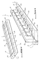
- la figure 1 est une vue en coupe transversale et en éclaté d'une structure préfabriquée conforme à l'invention;
- la figure 2 est une vue schématique en perspective d'un panneau plat préfabriqué pour une structure conforme à l'invention;
- la figure 3 est une vue schématique en perspective d'un panneau d'angle préfabriqué pour une structure conforme à l'invention;
- la figure 4 est une vue partielle en coupe transversale d'une jointure dans le système d'isolation d'une structure avec un raccord étanche injecté, suivant un mode de réalisation de l'invention;
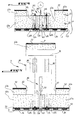
- la figure 5 est une vue similaire à la figure 4, avec des raccords étanches rapportés et collés suivant un autre mode de réalisation de l'invention.
- Figure 1 is a cross-sectional and exploded view of a prefabricated structure according to the invention;
- Figure 2 is a schematic perspective view of a prefabricated flat panel for a structure according to the invention;
- Figure 3 is a schematic perspective view of a prefabricated corner panel for a structure according to the invention;
- FIG. 4 is a partial view in cross section of a joint in the insulation system of a structure with an injected tight connection, according to an embodiment of the invention;
- Figure 5 is a view similar to Figure 4, with waterproof fittings reported and glued according to another embodiment of the invention.
En se reportant notamment à la figure 1, on voit une structure préfabriquée 1 qui permet de former des parois étanches et thermiquement isolantes pour la réalisation d'une enceinte de confinement ou réservoir, par exemple pour emmagasiner et/ou transporter un fluide à très basse température. Ici, et ce seulement à titre d'exemple, la structure 1 est un réservoir constitué par un assemblage de parois étanches et calorifugées, dans lequel un liquide cryogénique tel qu'un gaz liquéfié très froid, comme notamment du méthane, peut être emmagasiné.Referring in particular to FIG. 1, we see a
La structure 1 comprend une enveloppe interne étanche apte à contenir le fluide à emmagasiner, qui se compose par assemblage d'éléments préfabriqués formant conjointement pour chaque paroi de la structure 1, une barrière étanche interne ou primaire 2. Sur la figure 1, la barrière primaire 2 est formée par des éléments fins en métal tel que tôle d'acier inoxydable ou d'aluminium. La référence numérique 2a désigne des nervures en saillie parallèlement aux raccords 2b entre les différents éléments de la barrière 2, qui permettent à l'enveloppe constituée par cette barrière d'être sensiblement flexible, afin de pouvoir se déformer sous l'effet des sollicitations, notamment thermiques générées par le fluide emmagasiné dans celle-ci.The
Une cloison externe rigide 3 de la structure 1 fait office de support pour cette dernière. Suivant l'exemple illustré, cette cloison 3 est une tôle métallique auto-porteuse de cale ou de double-cale d'un navire marchand, tel que méthanier. Evidemment, d'autres types de cloisons rigides dont les propriétés mécaniques sont appropriées, comme notamment un mur en béton dans une construction à terre ferme, pourront être employées comme cloison externe de support de la structure 1.A rigid
Par ailleurs, un système d'isolation thermique désigné généralement en 4 est prévu entre la barrière primaire 2 et la cloison externe 3. Le système d'isolation ou de calorifugeage 4 de la structure 1 comporte notamment une couche interne d'isolation 42 à laquelle est liée la barrière primaire 2, ainsi qu'une couche externe d'isolation 43 solidaire de la cloison externe de support 3.Furthermore, a thermal insulation system generally designated at 4 is provided between the
Les couches externe et interne 42, 43 sont réalisées à partir d'un matériau d'isolation thermique étanche. Avantageusement, on utilisera une mousse plastique ou synthétique à cellules fermées. Une mousse à cellules fermées à base de polyuréthane ou de polychlorure de vinyle notamment pourra parfaitement convenir pour la réalisation de ces couches d'isolation 42,43.The outer and
Sur la figure 1, on voit que les deux couches d'isolation 42, 43 sont prises en sandwich ou enserrées entre deux panneaux de répartition des efforts 52 et 53. Ces panneaux 52, 53 respectivement interne et externe, sont par exemple réalisés à partir d'éléments assemblés en bois contre-plaqué ou laminé. Les panneaux interne et externe 52 et 53 permettent de répartir à peu près uniformément dans la structure et notamment le système d'isolation 4, les efforts par exemple liés aux déformations de la cloison externe 3 et de l'enveloppe définie par la barrière interne 2. Pour ce faire, le panneau 52 est en appui, et de préférence collé sur la surface supérieure (c'est-à-dire la plus proche de la barrière 2) de la couche d'isolation 42, tandis que le panneau externe 53 est en appui ,et de préférence collé sur la surface inférieure (à savoir en regard avec la cloison 3) de la couche d'isolation 43.In FIG. 1, it can be seen that the two
Puisque la structure 1 est préfabriquée, chaque couche d'isolation 42, 43 est constituée par juxtaposition de plaques isolantes en matière étanche, désignées en 42a ou 43a, respectivement, et dont la forme est généralement prismatique rectangulaire. Il va de soi que dans les parties en coin ou en arête de la structure 1, les plaques isolantes 42a ou 43a pourront être biseautées avec un angle approprié à celui qui est formé par la structure 1 au niveau de cette arête, afin de former des jointures les plus importantes possibles. De plus, les plaques 42a, 43a seront préfabriqués avec des dimensions standard, qui évidemment pourront être modifiées par découpage en fonction de la forme de la structure à réaliser.Since the
Les plaques isolantes 42a, 43a sont disposées bout-à-bout de façon à définir dans chaque couche 42,43 des jointures généralement linéaires 62, 63 respectivement. Ces jointures 62, 63 s'étendent généralement suivant un plan de direction perpendiculaire au plan médian des panneaux 52, 53, sur au moins toute l'épaisseur de la couche d'isolation correspondante 42, 43. Chacune des jointures 63 formées dans la couche externe est recouverte par une bande 70 qui est interposée et collée entre les deux couches de mousse isolante 42 et 43 et vient au droit d'une plaque 42a de la couche interne 42.The
Conformément à l'invention, les panneaux de répartition 53 sont fixés à la cloison externe 3, notamment par des vis ou analogues 35, visibles sur la figure 5. Ces vis 35 représentées sur les autres figures seulement par leur axe longitudinal, sont disposées en regard de trous 435, eux-mêmes formés dans la couche d'isolation externe 43, à distance des jointures 63 entre les différentes plaques juxtaposées 43a constituant cette couche. Par ailleurs, chacune des jointures 63 et tous les trous 435 en question sont remplis par un raccord 80 en matière thermiquement isolante et étanche. Ces raccords 80 isolants et étanches pourront notamment être réalisés dans le même matériau ou dans un matériau similaire à celui des couches d'isolation 42 et 43, par exemple en éthyl vinyle acétate. En outre, tous les raccords 80 disposés dans les jointures 63 et dans les trous 435 de la couche 43 sont collés pour adhérer hermétiquement aux parois du trou 435 ou de la jointure 63 correspondante, afin de rendre la couche externe 43 continue et étanche sur toute la surface définie par la structure 1.According to the invention, the
On comprend déjà qu'avec une telle structure 1, l'étanchéité secondaire est obtenue en rendant hermétiquement solidaires les plaques 43a et raccords 80, de façon que la couche préfabriquée d'isolation externe 43 forme, après son assemblage et son collage, une barrière secondaire continue et donc parfaitement étanche.It is already understood that with such a
En outre, les jointures 62 entre les plaques 42a de la couche d'isolation interne seront, de préférence, aussi obturées hermétiquement par des joints souples (éventuellement collés) en mastic liquide polymérisé par exemple. Dans ce cas, la barrière secondaire est constituée par tout le système d'isolation 4.In addition, the
Toutefois, puisque c'est notamment la couche externe d'isolation 43 qui garantit un bon confinement du fluide à l'intérieur de la structure 1 en cas de fissure ou analogue dans par exemple la barrière primaire 2, il n'est pas nécessaire que les bandes 70 de recouvrement des jointures 63 et des raccords 80 soient étanches et hermétiquement fixées entre les deux couches isolantes 42 et 43. Dès lors, ces bandes de recouvrement 70 auront pour principal rôle de maintenir assemblées les plaques 42a et 43a des couches d'isolation correspondantes du système 4. Dans ce but, il sera avantageux d'employer une feuille de renforcement telle qu'un tissu en fibre de verre ou analogue, que l'on collera au moins au niveau des jointures 63 et des trous 435, entre les deux couches d'isolation 42 et 43 correspondantes. Avec l'une de ses faces adhérant à au moins deux plaques d'isolation 42a, et son autre face adhérant à au moins deux plaques 43a, chaque bande de recouvrement 70 renforcera efficacement la cohésion entre les raccords de jointure 80 et les plaques d'isolation 42a, 43a.However, since it is in particular the
Afin d'obtenir le meilleur renforcement possible, chaque bande de recouvrement 70 devra s'étendre largement au-delà de la surface de la couche externe 43 où sont formés les trous 435 et la jointure 63 à recouvrir.In order to obtain the best possible reinforcement, each covering
On voit sur la figure 1 que les plaques d'isolation préfabriquées 42a et 43a sont disposées au sein de la structure 1 de façon décalée, pour que les jointures 63 et les trous 435 de deux plaques externes 43a se trouvent au droit d'une plaque interne 42a. Avec une telle disposition, on choisira la surface de chaque bande de renforcement 70 pour qu'elle soit sensiblement égale à celle de la plaque externe 42a correspondante. Il est intéressant si les impératifs d'assemblage des éléments préfabriqués de la structure 1 le permettent, de recouvrir entièrement la couche externe d'isolation 43 avec un tissu de renforcement sur lequel les bandes de renforcement 70 pourront être collées.It can be seen in FIG. 1 that the
On remarquera aussi ici qu'en prévoyant de disposer les trous 435 à distance des jointures 63, ceux-ci débouchent en regard d'une surface pleine des panneaux de répartition 53 correspondants, de façon qu'il est plus aisé d'obtenir une étanchéité entre la couche 43 et le panneau 53 correspondant, notamment grâce au collage de ces deux éléments préfabriqués.It will also be noted here that, by providing the
En se reportant maintenant à la figure 5 qui représente un premier mode de réalisation de l'invention, on voit que les raccords 80 prévus pour remplir les trous 435 ainsi que les jointures 63 illustrées, sont constitués par des pièces rapportées de forme correspondant à celle des orifices (63,435) à remplir dans la couche 43. Plus précisément, le raccord prévu pour venir se loger suivant le sens de la flèche F1 dans la jointure 63 et désigné en 83, est un joint plat étanche. Ce raccord en forme de joint plat 83 a une longueur suivant la direction de la flèche F1 qui est sensiblement égale à l'épaisseur de l'ensemble constitué par la couche 43 et les panneaux 53.Referring now to FIG. 5 which represents a first embodiment of the invention, it can be seen that the
D'autre part, on voit qu'un tampon 33 de préférence réalisé dans une mousse plastique souple étanche est interposé entre les panneaux 53 disposés de part et d'autre de la jointure 63, et la cloison externe 3. Ce tampon 33 dont la section suivant un plan transversal perpendiculaire au plan médian P de la jointure 63 est trapézoïdale, repose par l'une de ses faces parallèles dont la surface est la plus petite, contre la face interne de la cloison 3. En outre, les rebords longitudinaux de sa face parallèle la plus importante sont respectivement en appui contre la face externe en regard de la cloison 3 de l'un des panneaux 53 contigu à la jointure 63. Grâce au serrage des vis 35 de fixation des panneaux 53 sur la cloison externe 3, les rebords longitudinaux du tampon 33 sont serrés entre ces panneaux 53 et la cloison 3, à l'instar des patins d'appui 34 visibles sur les figures 1 et 4. Ce serrage des tampons 33 permet d'obtenir un contact étanche entre ces derniers et des panneaux 53. L'étanchéité de ce contact pourra encore être améliorée en appliquant un adhésif hermétique entre les rebords latéraux de chaque tampon 33 et les panneaux 53 correspondants. Ces patins 34 sont collés d'une part à la cloison externe 3 et d'autre part à l'un des panneaux 53.On the other hand, it can be seen that a
Bien que ceci ne soit pas visible sur les figures 1 et 4 notamment, les faces externes ou périphériques de chaque raccord 80 sont enduites d'une couche de colle appropriée, de préférence une colle moussante. Ainsi, lorsque le raccord 80 est introduit dans l'orifice (63) ou (435) correspondant, celui-ci adhère de façon hermétique aux plaques d'isolation 43a de la couche externe, et au tampon 33 afin de former une pièce unique continue, sans passage possible pour le fluide à emmagasiner dans la structure 1.Although this is not visible in FIGS. 1 and 4 in particular, the external or peripheral faces of each
Pour faciliter la réalisation ainsi que le montage du raccord 83 (ou de tout autre raccord 80 constitué par une pièce rapportée) il est possible que celui-ci soit obtenu par assemblage d'au moins deux éléments collés l'un à l'autre. De préférence, chaque élément sera symétrique à l'autre suivant un plan confondu avec le (ou l'un) des plans médians de l'orifice 63 ou 435 à remplir à l'aide de ce raccord en plusieurs éléments. Par exemple, le raccord 83 pourra être formé par assemblage de deux éléments symétriques par rapport au plan médian P. Les faces de ces éléments constituant le raccord 83 qui s'étendent suivant le plan P sont enduites d'un adhésif approprié, de préférence moussant, et assemblées juste avant montage et collage du raccord ainsi constitué dans la jointure 63.To facilitate the production as well as the fitting of the fitting 83 (or of any
Au vu de la figure 1, on remarque qu'à proximité d'un angle défini par deux parois de la structure 1, on prévoit entre le raccord 80 qui est ici constitué par une pièce rapportée, et la cloison externe 3 une butée de positionnement plaques d'isolation 43a de la couche externe 43. A cet effet, à la place du tampon 33 décrit plus haut, on dispose du côté opposé à la plaque 43a définissant ledit angle, une barre 33' enserrée et collée entre le panneau 53 correspondant à l'autre plaque 43a et la cloison externe 3. De plus, on place en appui contre cette barre 33' une série de cales 36 reposant contre les faces d'extrémité d'un patin 34, du panneau 53 et de la plaque 43 situées du côté de l'angle formé par la structure 1. Ces cales comprendront généralement de droite à gauche sur la figure 1, par exemple une pièce métallique, un raccord en mastic et une cale en bois contre-plaqué ou laminé. La base du raccord 80 correspondant est évidemment collée de façon étanche sur ce jeu de cales 36. Ainsi, il est possible d'immobiliser les éléments préfabriqués en question dans une position appropriée suivant la direction perpendiculaire à l'arête de l'angle formé par la structure 1 à cet endroit.In view of Figure 1, we note that near an angle defined by two walls of the
On remarque également sur la figure 1 qu'un espace vide 56 est prévu dans la jointure 63 entre la couche d'isolation 43 et la cale en métal 36 située du côté opposé au coin défini par la structure 1. Un remplissage 86 par exemple en mastic dont la forme allongée correspond à celle de l'espace 56, est prévu dans cet espace pour que le raccord 80 puisse venir adhérer sur toute sa base et obturer de façon étanche le fond de la jointure 63 entre les plaques d'isolation 43a.Note also in Figure 1 that an empty space 56 is provided in the joint 63 between the
Similairement à ce qui vient d'être expliqué, des raccords 85 représentés sur la figure 5 et prévus pour remplir les trous 435 sont en forme de plots ou rondins cylindriques de forme correspondant à celle de chaque trou. Leurs faces d'extrémité venant en regard du panneau correspondant 53 sont évidées à leur centre, de manière que la vis 35 faisant saillie dans ce trou 435 puisse s'y loger. Toutefois, à proximité de la périphérie du rondin formant raccord 85, on prévoit une surface annulaire d'extrémité qui peut être mise en contact avec le panneau 53 constituant le fond du trou 435, et être collée hermétiquement à ce panneau autour de la vis 35. De même, les parois cylindriques du raccord 85 sont enduites de colle appropriée, de préférence moussante, pour que ce dernier forme après prise de la colle une seule pièce étanche avec la plaque isolante 43a à l'intérieur de laquelle il vient se loger.Similar to what has just been explained,
Par ailleurs, tout comme le joint formant raccord 83, la pièce rapportée cylindrique 85 pourra aussi être obenue par assemblage et collage de deux éléments, par exemple en mousse de polyuréthane à cellules fermées.Furthermore, like the joint forming a fitting 83, the
Sur la figure 4, le raccord remplissant la jointure 63 entre les deux plaques d'isolation juxtaposées 43a est obtenu in situ. Plus spécialement, le fond de la jointure 63 est hermétiquement obturé par un tampon 33 généralement identique à celui qui a été décrit plus haut. Un outil d'injection 100 est fixé sur le système d'isolation 4, afin d'obturer la partie débouchante de la jointure 63. L'outil d'injection 100 est composé par une platine 103 apte à venir hermétiquement en appui contre la face supérieure de la couche d'isolation 43 en recouvrant la jointure 63, et par au moins deux goujons d'extension 135 prévus pour se fixer sur les vis 35. Ainsi, la platine 103 de l'outil 100 peut être plaquée de façon étanche contre la couche externe d'isolation 43, de sorte que l'espace intérieur défini par la jointure 63 est hermétiquement clos. De plus, la platine 103 de l'outil 100 comprend une bouche d'injection 160 associée à au moins un évent qui permet de mettre en communication l'intérieur de la jointure 63 et une source S de matière plastique isolante et étanche pouvant s'expanser, telle que de préférence du polyuréthane à cellules fermées.In FIG. 4, the connection filling the joint 63 between the two juxtaposed
Une fois l'outil 100 et la source S mis en place comme illustré sur la figure 4, la matière plastique de la source S est injectée sous une pression appropriée dans l'espace défini par la jointure 63, afin de remplir celui-ci complètement. Lorsque la matière expansible injectée désignée ici en 84 est séchée et qu'elle adhère hermétiquement aux parois de la jointure 63 et du tampon 33, on a obtenu un raccord 80. Une fois que l'outil 100 est démonté, la matière 84 du raccord 80 et les deux plaques de matière isolante 43a juxtaposées au raccord 63 correspondant ne forment plus qu'une seule pièce continue, et par conséquent ne peuvent en aucun cas laisser passer un fluide. On notera ici que bien que ceci ne soit pas illustré, les trous 435 prévus pour l'accès aux vis d'assemblage ou fixation 35 peuvent également être remplis par injection d'une matière étanche expansible telle que celle désignée en 84.Once the
Evidemment, grâce à un outil d'injection tel que celui qui vient d'être décrit, la matière 84 pourra remplir la jointure 63 jusqu'à fleur de la couche externe d'isolation 43, de manière que les plaques 43a seront reliées de façon continue par le raccord 80 ainsi réalisé, et qu'il sera aisé d'appliquer sur une surface ainsi formée une bande de renforcement 70.Obviously, thanks to an injection tool such as that which has just been described, the
On précisera ici que la pression d'injection de la matière 84 ainsi que la force nécessaire pour loger les raccords 80 constitués par des pièces rapportées telles que ceux qui sont illustrés sur la figure 5, seront choisies pour qu'en position définitive de ces raccords 80 et des plaques juxtaposées 43a, les contraintes générées par ces raccords 80 à l'intérieur de la couche externe 43 aient une valeur négligeable, notamment par rapport à la force de cohésion exercée par les adhésifs (y compris par la matière injectée 84) ainsi que par les bandes de recouvrement 70 qui relient les raccords 80 et les plaques 43a.It will be specified here that the injection pressure of the material 84 as well as the force necessary to accommodate the
D'après les figures 1 et 3, on remarque que dans les coins à 90° ou avec un angle différent, le panneau de répartition des efforts 52 est remplacé par une cornière métallique. Comme on le voit mieux sur la figure 3, la cornière métallique est constituée par des éléments 52a en métal inoxydable tel qu'acier traité ou aluminium, qui sont juxtaposés et assemblés à l'aide de vis 45 (figure 1) venant se fixer dans la matière des plaques 42a constituant la couche interne d'isolation 42 du système 4. Un joint souple 62a tel que celui qui est décrit en se reportant à la figure 1, peut être interposé entre les éléments 42a de façon à adhérer à ceux-ci.From Figures 1 and 3, we note that in the corners at 90 ° or with a different angle, the
Ici aussi, lorsque les plaques biseautées 43a seront assemblées à l'aide de raccord d'angle 80 tel que celui de la figure 3, l'ensemble de la couche 43 sera recouvert d'une bande 70 de préférence en fibre de verre. Ensuite, les plaques d'isolation 42a formant par juxtaposition la couche interne 42 seront assemblées, avec au niveau du coin défini par la structure 1, un raccord d'angle 82 (figure 1) hermétiquement collé aux plaques 42a qui lui sont contigües.Here too, when the
Similairement à la structure préfabriquée 1 de la figure 3 qui forme une paroi d'angle, on a représenté sur la figure 2 une structure plane 1 constituée d'éléments préfabriqués assemblés conformément à l'invention.Similar to the
Dans la structure préfabriquée de la figure 2, le panneau 52 est constitué d'éléments fixés aux plaques d'isolation correspondantes 42a par collage. On pourra prévoir sur un tel panneau 52 des inserts métalliques 142 pour la fixation d'outils notamment. Des bandes en métal inoxydable 166 qui s'étendent transversalement à chacun des éléments du panneau 52 sont respectivement serties dans des logements appropriés disposés en alignement et formés dans les éléments qui constituent par juxtaposition ce panneau.In the prefabricated structure of FIG. 2, the
Comme on l'a représenté schématiquement sur la figure 2, il sera également possible avec l'élément préfabriqué visible sur cette figure d'interposer entre la couche 43 et la couche 42 un tissu en fibre de verre 70 qui s'étend au-delà des trous 435 de cet élément préfabriqué. De telles feuilles pourront être collées les unes aux autres par les bandes de recouvrement pour ne former qu'une seule enveloppe de renforcement sur toute la surface de la structure 1.As shown schematically in Figure 2, it will also be possible with the prefabricated element visible in this figure to interpose between
On a donc obtenu conformément à l'invention une structure 1 qui, en cas de fuite à travers la barrière primaire 2 permet de faire que le gradient thermique dans le système d'isolation 4 n'est pas affecté.A
Il convient aussi de préciser ici que puisque la couche 70 n'a plus qu'une fonction mécanique, il n'est plus nécessaire de prévoir de feuille métallique étanche prise en sandwich au niveau des bandes et de la feuille de recouvrement. De fait, en plus des diminutions de coûts liées à l'obtention de la structure à partir d'éléments préfabriqués, l'invention permet de réduire de manière importante les coûts de fabrication des réservoirs pour les liquides cryogéniques dans par exemple des navires commerciaux, tout en garantissant une qualité d'isolation et d'étanchéité supérieure à celle qu'on pouvait obtenir dans l'art antérieur.Notamment, le déplacement de l'étanchéité secondaire permet d'employer une nuance d'acier moins coûteuse pour la cloison externe de support.It should also be specified here that since the
Evidemment, l'invention n'est nullement limitée aux modes de réalisation qui viennent d'être décrits, mais comprend tous les équivalents et les combinaisons des moyens techniques expliqués et illustrés, si celles-ci sont effectuées suivant son esprit.Obviously, the invention is in no way limited to the embodiments which have just been described, but includes all the equivalents and combinations of the technical means explained and illustrated, if these are carried out according to the spirit.
Ainsi, entre deux plaques d'isolation de la couche externe, on pourra prévoir que certains raccords étanches soient obtenus par injection et d'autres par collage de pièces rapportées.Thus, between two insulating plates of the external layer, provision may be made for certain sealed connections to be obtained by injection and others by bonding of added parts.
Claims (10)
Applications Claiming Priority (2)
| Application Number | Priority Date | Filing Date | Title |
|---|---|---|---|
| FR929206136A FR2691520B1 (en) | 1992-05-20 | 1992-05-20 | Prefabricated structure for forming watertight and thermally insulating walls for containment of a fluid at very low temperature. |
| FR9206136 | 1992-05-20 |
Publications (2)
| Publication Number | Publication Date |
|---|---|
| EP0573327A1 true EP0573327A1 (en) | 1993-12-08 |
| EP0573327B1 EP0573327B1 (en) | 1999-01-27 |
Family
ID=9429982
Family Applications (1)
| Application Number | Title | Priority Date | Filing Date |
|---|---|---|---|
| EP93401304A Expired - Lifetime EP0573327B1 (en) | 1992-05-20 | 1993-05-19 | Prefabricated, fluid-tight and heat-insulating wall structure for vessels for cryogenic fluids |
Country Status (12)
| Country | Link |
|---|---|
| US (1) | US5501359A (en) |
| EP (1) | EP0573327B1 (en) |
| JP (1) | JP3788808B2 (en) |
| KR (1) | KR100258206B1 (en) |
| AU (1) | AU4076193A (en) |
| CA (1) | CA2113822A1 (en) |
| DE (1) | DE69323240D1 (en) |
| ES (1) | ES2127799T3 (en) |
| FI (1) | FI940259A (en) |
| FR (1) | FR2691520B1 (en) |
| PL (1) | PL302155A1 (en) |
| WO (1) | WO1993023699A1 (en) |
Cited By (15)
| Publication number | Priority date | Publication date | Assignee | Title |
|---|---|---|---|---|
| FR2724623A1 (en) * | 1994-09-20 | 1996-03-22 | Gaztransport Et Technigaz | IMPROVED WATERPROOF AND THERMALLY INSULATING TANK INTEGRATED INTO A CARRIER STRUCTURE |
| FR2861060A1 (en) | 2003-10-16 | 2005-04-22 | Gaz Transport & Technigaz | Sealed wall structure for internal lining of sealed and thermally insulating tank, has reinforcing convex ridge protruding on side of internal face or external face and made locally on at least one lateral face of corrugation |
| EP1698649A2 (en) | 2005-03-04 | 2006-09-06 | Gaz Transport et Technigaz | Glassfiber-reinforced polyurethane-polyisocyanurate foam |
| DE102006016796A1 (en) * | 2006-04-10 | 2007-10-11 | Warnow Design Gmbh | Tank system for storage and transport of liquefied natural gas, has inner structure with composite panels having insulation layers connected with each other, and barrier layers of panels connected with each other in gas-tight manner |
| DE102006020699B4 (en) * | 2006-05-04 | 2008-08-14 | Warnow Design Gmbh | Container for storing cryogenic liquid media and method for its production |
| DE102007061367A1 (en) | 2007-12-19 | 2009-06-25 | Warnow Design Gmbh | Outer supporting structure's inner side surface insulating and sealing device for e.g. fuel tank of ship for storing liquefied natural gas, has plate segments connected with each other in edge regions by form fit connection unit |
| FR2931535A1 (en) * | 2008-05-21 | 2009-11-27 | Gaztransp Et Technigaz | BONDING FIXING OF INSULATION BLOCKS FOR LIQUEFIED GAS STORAGE TANK USING CORRUGATED CORDS |
| RU2443595C2 (en) * | 2007-01-23 | 2012-02-27 | Альстом | Method of fabricating reservoir isolating and sealing wall |
| WO2013083892A1 (en) | 2011-12-08 | 2013-06-13 | Gaztransport Et Technigaz | Construction of a fluidtight membrane from metal plates |
| RU2526870C1 (en) * | 2013-02-26 | 2014-08-27 | Российская Федерация, от имени которой выступает Министерство промышленности и торговли Российской Федерации (Минпромторг России) | Heat-insulating sealed wall of reservoir made of polymeric composite materials for compressed natural gas |
| CN110892189A (en) * | 2017-06-28 | 2020-03-17 | 气体运输技术公司 | Fluid sealing membrane and method of assembling a fluid sealing membrane |
| CN111503509A (en) * | 2014-09-26 | 2020-08-07 | 气体运输技术公司 | Sealed insulated tank for storing fluid, vessel, loading and unloading method and transport system |
| FR3092837A1 (en) | 2019-02-18 | 2020-08-21 | Gaztransport Et Technigaz | METHACRYLATE COPOLYMERS, AND THEIR USES FOR THE PREPARATION OF POLYURETHANE FOAM |
| CN111630311A (en) * | 2018-01-23 | 2020-09-04 | 气体运输技术公司 | Sealed heat insulation tank |
| CN111656083A (en) * | 2018-01-23 | 2020-09-11 | 气体运输技术公司 | Sealed heat insulation tank |
Families Citing this family (120)
| Publication number | Priority date | Publication date | Assignee | Title |
|---|---|---|---|---|
| FR2780942B1 (en) * | 1998-07-10 | 2000-09-08 | Gaz Transport & Technigaz | WATERPROOF AND THERMALLY INSULATING TANK WITH IMPROVED ANGLE STRUCTURE, INTEGRATED INTO A SHIP-CARRIED STRUCTURE |
| FR2781557B1 (en) | 1998-07-24 | 2000-09-15 | Gaz Transport & Technigaz | IMPROVEMENT FOR A WATERPROOF AND THERMALLY INSULATING TANK WITH PREFABRICATED PANELS |
| FR2813111B1 (en) * | 2000-08-18 | 2002-11-29 | Gaz Transport & Technigaz | WATERPROOF AND THERMALLY INSULATING TANK IMPROVED LONGITUDINAL AREAS |
| JP2004537401A (en) | 2001-08-08 | 2004-12-16 | ブラウン ユニバーシティ リサーチ ファウンデーション | Fine grinding method of hydrophobic drug |
| KR100457880B1 (en) * | 2001-11-14 | 2004-11-18 | 대우조선해양 주식회사 | Cargo containment system for LNG ship |
| WO2005113920A2 (en) * | 2004-05-20 | 2005-12-01 | Exxonmobil Upstream Research Company | Lng containment system and method of assembling lng containment system |
| WO2006003192A1 (en) * | 2004-07-06 | 2006-01-12 | Shell Internationale Research Maatschappij B.V. | Container for storing liquefied gas |
| FR2877638B1 (en) * | 2004-11-10 | 2007-01-19 | Gaz Transp Et Technigaz Soc Pa | THERMALLY INSULATED AND THERMALLY INSULATED TANK WITH COMPRESSION-RESISTANT CALORIFIC ELEMENTS |
| US7204195B2 (en) | 2004-12-08 | 2007-04-17 | Korea Gas Corporation | Ship with liquid tank |
| KR100499710B1 (en) * | 2004-12-08 | 2005-07-05 | 한국가스공사 | Lng storage tank installed inside the ship and manufacturing method the tank |
| JP4616279B2 (en) * | 2004-12-08 | 2011-01-19 | コリア ガス コーポレイション | Storage tank for liquefied natural gas and method for producing the same |
| KR100667500B1 (en) * | 2005-04-15 | 2007-01-10 | 한국가스공사 | Lng storage tank and modules for constructing it |
| KR100644217B1 (en) * | 2006-04-20 | 2006-11-10 | 한국가스공사 | Lng storage tank having improved insulation structure and manufacturing method |
| KR100760482B1 (en) * | 2006-07-12 | 2007-09-20 | 한국과학기술원 | Structure and method for connecting insulation protective wall of liquefied natural gas tank ship |
| JP4451439B2 (en) * | 2006-09-01 | 2010-04-14 | 韓国ガス公社 | Structure for forming a storage tank for liquefied natural gas |
| FR2909356B1 (en) | 2006-11-30 | 2009-01-16 | Gaztransp Et Technigaz Soc Par | BONDED FIXING OF INSULATING BLOCKS FOR LIQUEFIED GAS TRANSPORT TANK USING CORRUGATED CORDS |
| CA2670920C (en) * | 2006-12-06 | 2015-05-26 | Shell Canada Limited | Use of a composite material as a barrier under cryogenic conditions |
| KR100766309B1 (en) | 2007-04-30 | 2007-10-12 | (주)삼우멤코 | Forming machine of membrane for lng storage tank coupled connected with support bar |
| WO2009059617A1 (en) * | 2007-11-07 | 2009-05-14 | Aker Mtw Werft Gmbh | Method and panel system for the construction of containers for cryogenic media |
| US20090293506A1 (en) * | 2008-05-30 | 2009-12-03 | Daewoo Shipbuilding & Marine Engineering Co., Ltd. | Semi-Submersible Offshore Structure Having Storage Tanks for Liquified Gas |
| KR101122292B1 (en) * | 2008-06-19 | 2012-03-21 | 삼성중공업 주식회사 | Insulation strusture of lng carrier cargo tank and method for constructing the same |
| KR101215629B1 (en) * | 2008-06-20 | 2012-12-26 | 삼성중공업 주식회사 | Insulation panel for corner area of lng cargo containment system |
| ATE546349T1 (en) * | 2008-08-21 | 2012-03-15 | Daewoo Shipbuilding & Marine | LIQUID GAS STORAGE TANK AND VESSEL CONTAINING SUCH TANK |
| WO2010039198A1 (en) | 2008-09-23 | 2010-04-08 | Aerovironment Inc. | Cryogenic liquid tank |
| FR2944335B1 (en) * | 2009-04-14 | 2011-05-06 | Gaztransp Et Technigaz | STOPPING THE SECONDARY MEMBRANE FROM AN LNG TANK |
| US20110168722A1 (en) * | 2010-01-13 | 2011-07-14 | BDT Consultants Inc. | Full containment tank |
| CN102792084B (en) * | 2010-03-17 | 2014-11-26 | 气体产品与化学公司 | Cryogenic storage tank |
| KR101195605B1 (en) * | 2010-07-30 | 2012-10-29 | 삼성중공업 주식회사 | Cargo for liquefied gas carrier ship |
| FR2972242B1 (en) * | 2011-03-01 | 2014-10-17 | Gaztransp Et Technigaz | FIXING INSULATING PANELS ON A CARRIER WALL ACCORDING TO A REPEATED PATTERN |
| WO2012154015A2 (en) * | 2011-05-12 | 2012-11-15 | 대우조선해양 주식회사 | Structure and manufacturing method of liquefied natural gas storage container |
| DK2653625T3 (en) * | 2012-04-20 | 2019-03-11 | Halfen Gmbh | Thermally insulating structural element |
| KR20170021359A (en) * | 2012-11-13 | 2017-02-27 | 엔엘아이 이노베이션 에이에스 | Support assembly |
| FR3004507B1 (en) * | 2013-04-11 | 2019-04-26 | Gaztransport Et Technigaz | DECOUPLING THE ONDULATIONS OF A SEALED BARRIER |
| FR3004510B1 (en) | 2013-04-12 | 2016-12-09 | Gaztransport Et Technigaz | SEALED AND THERMALLY INSULATING TANK FOR STORAGE OF A FLUID |
| FR3004509B1 (en) | 2013-04-12 | 2016-11-25 | Gaztransport Et Technigaz | ANGLE STRUCTURE OF A SEALED AND THERMALLY INSULATING STORAGE OF A FLUID |
| FR3008163B1 (en) * | 2013-07-02 | 2015-11-13 | Gaztransp Et Technigaz | CALORIFUGE ELEMENT SUITABLE FOR THE PRODUCTION OF AN INSULATING BARRIER IN A WATERPROOF AND INSULATING TANK |
| FR3009745B1 (en) | 2013-08-15 | 2016-01-29 | Gaztransp Et Technigaz | SEALED AND THERMALLY INSULATING TANK WITH ANGLE PIECE |
| JP6331344B2 (en) * | 2013-11-15 | 2018-05-30 | 株式会社Ihi | Membrane anchor mechanism |
| RU2566588C2 (en) * | 2013-11-28 | 2015-10-27 | Российская Федерация, От Имени Которой Выступает Министерство Промышленности И Торговли Российской Федерации | Method to manufacture blocks of heat insulation tight wall of new type reservoir from polymer composite materials for liquefied natural gas |
| GB2535397B (en) * | 2014-02-28 | 2017-10-04 | Mgi Thermo Pte Ltd | An LNG fuel containment apparatus incorporating multi-layered insulation panels |
| CN106573664B (en) * | 2014-07-30 | 2019-05-21 | 三星重工业有限公司 | Anti- wall flaps and liquefied gas cargo hold and its manufacturing method for liquefied gas cargo hold |
| FR3025122B1 (en) | 2014-09-01 | 2017-03-31 | Gaztransport Et Technigaz | ANGLE PIECE AND FOLDING DEVICE AND METHOD FOR FORMING CORRUGATION IN AN ANGLE PIECE |
| KR101652219B1 (en) * | 2014-09-19 | 2016-08-31 | 삼성중공업 주식회사 | Cargo for liquefied gas and manufacturing method thereof |
| FR3028305A1 (en) | 2014-11-10 | 2016-05-13 | Gaztransport Et Technigaz | DEVICE AND METHOD FOR COOLING A LIQUEFIED GAS |
| FR3032258B1 (en) | 2015-01-30 | 2017-07-28 | Gaztransport Et Technigaz | STORAGE AND TRANSPORTATION INSTALLATION OF A CRYOGENIC FLUID EMBEDDED ON A SHIP |
| FR3033874B1 (en) | 2015-03-20 | 2018-11-09 | Gaztransport Et Technigaz | METHOD FOR COOLING A LIQUEFIED GAS |
| US20170167782A1 (en) * | 2015-12-09 | 2017-06-15 | Whirlpool Corporation | Insulating material with renewable resource component |
| FR3049331B1 (en) | 2016-03-22 | 2018-09-14 | Gaztransport Et Technigaz | FUEL GAS SUPPLY INSTALLATION OF A GAS CONSUMER ORGAN AND LIQUEFACTION OF SUCH FUEL GAS |
| FR3058498B1 (en) | 2016-11-09 | 2019-08-23 | Gaztransport Et Technigaz | ANGLE STRUCTURE OF A SEALED AND THERMALLY INSULATING TANK AND METHOD FOR ASSEMBLING THE SAME |
| FR3060098B1 (en) | 2016-12-09 | 2019-08-16 | Gaztransport Et Technigaz | SEALED AND THERMALLY INSULATED TANK |
| FR3065941A1 (en) | 2017-05-05 | 2018-11-09 | Gaztransport Et Technigaz | METHOD FOR HANDLING LIQUEFIED GAS CARGO AND STORAGE PLANT |
| WO2018220331A1 (en) | 2017-06-01 | 2018-12-06 | Gaztransport Et Technigaz | Sealed and thermally insulating tank |
| FR3068763B1 (en) * | 2017-07-04 | 2020-10-02 | Gaztransport Et Technigaz | WATERPROOF AND THERMALLY INSULATED TANK INCLUDING A CORNER. |
| FR3069044B1 (en) | 2017-07-13 | 2020-10-30 | Gaztransport Et Technigaz | WATERPROOF AND THERMALLY INSULATED TANK |
| FR3069043B1 (en) | 2017-07-13 | 2020-10-30 | Gaztransport Et Technigaz | WATERPROOF AND THERMALLY INSULATED TANK WITH CURVED SUPPORT STRIP |
| FR3069903B1 (en) | 2017-08-07 | 2019-08-30 | Gaztransport Et Technigaz | SEALED AND THEMIALLY INSULATING TANK |
| FR3072758B1 (en) | 2017-10-20 | 2019-11-01 | Gaztransport Et Technigaz | SEALED AND THERMALLY INSULATING TANK WITH SEVERAL ZONES |
| WO2019077253A1 (en) | 2017-10-20 | 2019-04-25 | Gaztransport Et Technigaz | Sealed and thermally insulating tank with several areas |
| FR3073602B1 (en) | 2017-11-10 | 2019-11-22 | Gaztransport Et Technigaz | METHOD FOR DETERMINING AN OPTIMUM VALUE OF AT LEAST ONE PARAMETER FOR IMPLEMENTING A METHOD FOR COLDING A WATERPROOF AND THEMALLY INSULATING TANK |
| FR3077617B1 (en) | 2018-02-07 | 2022-08-19 | Gaztransport Et Technigaz | INSTALLATION FOR THE STORAGE AND TRANSPORT OF A LIQUEFIED GAS |
| FR3077865B1 (en) | 2018-02-09 | 2020-02-28 | Gaztranport Et Technigaz | WATERPROOF AND THERMALLY INSULATING TANK COMPRISING INTER-PANEL INSULATING CAPS |
| FR3077764B1 (en) | 2018-02-09 | 2020-01-17 | Gaztransport Et Technigaz | PROCESS FOR MANUFACTURING A WATERPROOF AND THERMALLY INSULATING TANK WALL COMPRISING INTER-PANEL INSULATING CAPS |
| CN111886488B (en) | 2018-03-21 | 2022-10-25 | 气体运输技术公司 | Bell-shaped leakage detection device for sealing membrane |
| FR3079301B1 (en) | 2018-03-21 | 2020-10-30 | Gaztransport Et Technigaz | METHOD FOR DIFFUSION OF A TRACE GAS AND METHOD FOR TESTING THE TIGHTNESS OF A MEMBRANE |
| FR3080832B1 (en) | 2018-05-02 | 2020-10-30 | Gaztransport Et Technigaz | WATERPROOF AND THERMALLY INSULATED TANK EQUIPPED WITH A LOADING / UNLOADING TOWER |
| WO2019211551A1 (en) | 2018-05-02 | 2019-11-07 | Gaztransport Et Technigaz | Sealed and thermally insulating tank provided with a loading/unloading tower |
| FR3081041B1 (en) | 2018-05-11 | 2021-03-19 | Gaztransport Et Technigaz | PROCESS FOR ASSEMBLING A WATERPROOF AND THERMALLY INSULATING TANK |
| CN112469983B (en) | 2018-05-22 | 2023-07-11 | 气体运输技术公司 | Leak detection apparatus |
| FR3082015B1 (en) | 2018-05-31 | 2021-11-05 | Gaztransport Et Technigaz | METHOD FOR MANAGING THE FILLING LEVELS OF TANKS |
| FR3082595B1 (en) | 2018-06-13 | 2020-06-19 | Gaztransport Et Technigaz | WATERPROOF AND THERMALLY INSULATING TANK |
| FR3082596B1 (en) | 2018-06-15 | 2020-06-19 | Gaztransport Et Technigaz | WATERPROOF AND THERMALLY INSULATING CONTINUOUS WAVES TANK IN THE LIQUID DOME |
| FR3082916B1 (en) | 2018-06-25 | 2020-06-19 | Gaztransport Et Technigaz | METHOD FOR ASSEMBLING A LIQUID DOME |
| FR3083589B1 (en) | 2018-07-06 | 2022-04-08 | Gaztransport Et Technigaz | LOADING AND/OR UNLOADING TOWER EQUIPPED WITH A LIQUEFIED GAS SPRAYING DEVICE |
| CN109606569B (en) * | 2018-07-26 | 2021-09-21 | 沪东中华造船(集团)有限公司 | Sealing structure at joint of insulating blocks of B-type enclosure system |
| CN109606553B (en) * | 2018-07-26 | 2021-09-17 | 沪东中华造船(集团)有限公司 | Method for sealing joint of insulating blocks of B-type enclosure system |
| FR3087537B1 (en) | 2018-10-22 | 2021-01-29 | Gaztransport Et Technigaz | LEAKAGE TEST PROCEDURE OF A MEMBRANE AND ASSOCIATED LEAK DETECTION DEVICE |
| FR3094477B1 (en) | 2019-03-25 | 2021-09-24 | Gaztransport Et Technigaz | Mastic bead manufacturing process |
| FR3094448B1 (en) | 2019-03-26 | 2022-06-17 | Gaztransport Et Technigaz | Watertight and thermally insulated tank |
| FR3095802B1 (en) | 2019-05-09 | 2023-03-24 | Gaztransport Et Technigaz | Method and device for determining sloshing |
| FR3096457B1 (en) | 2019-05-21 | 2021-04-16 | Gaztransport Et Technigaz | LEAK DETECTION BELL AND ITS PROCESS FOR USE |
| FR3096458B1 (en) | 2019-05-21 | 2021-04-23 | Gaztransport Et Technigaz | Leak detection device |
| FR3097934B1 (en) | 2019-06-28 | 2022-01-28 | Gaztransport Et Technigaz | Method of manufacturing a corner structure for a tank |
| FR3099077B1 (en) | 2019-07-23 | 2022-06-10 | Gaztransport Et Technigaz | Method of manufacturing a wall for a sealed and thermally insulating tank |
| FR3099226B1 (en) | 2019-07-23 | 2023-03-24 | Gaztransport Et Technigaz | Waterproofing membrane for sealed fluid storage tank |
| FR3099538B1 (en) | 2019-07-31 | 2022-06-10 | Gaztransport Et Technigaz | Watertight and thermally insulated tank for floating structure |
| KR20220045967A (en) | 2019-08-09 | 2022-04-13 | 가즈트랑스포르 에 떼끄니가즈 | Method of manufacturing a sealed and thermally insulated tank wall with interpanel insulating inserts |
| JP2022543675A (en) | 2019-08-09 | 2022-10-13 | ギャズトランスポルト エ テクニギャズ | Closed insulated tank with inter-panel insulation inserts |
| FR3100860B1 (en) | 2019-09-18 | 2022-03-25 | Gaztransport Et Technigaz | Watertight and thermally insulated tank |
| FR3102533B1 (en) | 2019-10-25 | 2023-12-22 | Gaztransport Et Technigaz | Device and method for manufacturing a waterproof and thermally insulating tank corner structure |
| FR3103024B1 (en) | 2019-11-13 | 2021-11-05 | Gaztransport Et Technigaz | Sealed and thermally insulating tank |
| FR3103023B1 (en) | 2019-11-13 | 2021-10-08 | Gaztransport Et Technigaz | Sealed and thermally insulating tank with anti-convective insulating gaskets |
| FR3103534B1 (en) | 2019-11-22 | 2022-03-25 | Gaztransport Et Technigaz | Installation for the storage of a liquefied gas |
| FR3106193B1 (en) | 2020-01-10 | 2023-11-24 | Gaztransport Et Technigaz | Storage facility for liquefied gas |
| FR3108980B1 (en) | 2020-04-02 | 2022-02-25 | Gaztransport Et Technigaz | Membrane tightness test method and associated leak detection device |
| FR3109978B1 (en) | 2020-05-11 | 2022-04-08 | Gaztransport Et Technigaz | Liquid dome of a storage tank for liquefied gas comprising an opening fitted with an additional hatch |
| FR3110669A1 (en) | 2020-05-20 | 2021-11-26 | Gaztransport Et Technigaz | Storage facility for liquefied gas |
| FR3110667B1 (en) | 2020-05-20 | 2022-04-29 | Gaztransport Et Technigaz | Liquid dome of a storage tank for liquefied gas |
| FR3111176B1 (en) | 2020-06-09 | 2022-09-02 | Gaztransport Et Technigaz | Tank wall for watertight and thermally insulating tank |
| FR3112838B1 (en) | 2020-07-24 | 2022-07-22 | Gaztransport Et Technigaz | System and method for heating a storage tank for liquefied gas |
| FR3114863B1 (en) | 2020-10-02 | 2023-01-13 | Gaztransport Et Technigaz | Assembly process and installation of storage tank for liquefied gas |
| FR3115880B1 (en) | 2020-10-29 | 2023-05-26 | Gaztransport Et Technigaz | Leak test device for a sealed and thermally insulating tank membrane and associated leak detection method |
| CN112032550B (en) | 2020-11-06 | 2021-03-26 | 中太海事技术(上海)有限公司 | A bimetal low temperature film storage cabin for liquefied natural gas stores |
| CN114623372A (en) * | 2020-11-06 | 2022-06-14 | 中太海事技术(上海)有限公司 | Land storage container for storing liquefied gas |
| CN114440117A (en) * | 2020-11-06 | 2022-05-06 | 中太海事技术(上海)有限公司 | Standard template for storage structure and liquefied natural gas storage structure |
| FR3116587B1 (en) | 2020-11-20 | 2022-10-07 | Gaztransport Et Technigaz | Liquid dome of a storage tank for liquefied gas |
| FR3117993A1 (en) | 2020-12-22 | 2022-06-24 | Gaztransport Et Technigaz | Vessel comprising a tank |
| FR3119660B1 (en) | 2021-02-09 | 2023-12-29 | Gaztransport Et Technigaz | Float holder device |
| FR3122477B1 (en) | 2021-04-29 | 2023-12-08 | Gaztransport Et Technigaz | Storage facility for liquefied gas |
| FR3122400A1 (en) | 2021-04-30 | 2022-11-04 | Gaztransport Et Technigaz | Ro-ro ship comprising a tank for the storage of liquefied gas |
| FR3122401B1 (en) | 2021-04-30 | 2024-04-05 | Gaztransport Et Technigaz | Ro-ro ship including a tank for storing liquefied gas |
| FR3123106B1 (en) | 2021-05-18 | 2023-12-08 | Gaztransport Et Technigaz | Method for closing a sealing membrane for a waterproof and thermally insulating tank |
| FR3123962B1 (en) | 2021-06-15 | 2023-12-08 | Gaztransport Et Technigaz | Method and device for estimating a probability of damage due to the sloshing of a liquid load during an operation of transferring said liquid load between two floating structures |
| FR3128508A1 (en) | 2021-10-22 | 2023-04-28 | Gaztransport Et Technigaz | Watertight and thermally insulated tank |
| FR3128509A1 (en) | 2021-10-27 | 2023-04-28 | Gaztransport Et Technigaz | Watertight and thermally insulated tank |
| FR3129704B1 (en) | 2021-11-30 | 2023-11-24 | Gaztransport Et Technigaz | Process for assembling a waterproof and thermally insulating tank integrated into a supporting structure |
| FR3130931B1 (en) | 2021-12-17 | 2023-12-22 | Gaztransport Et Technigaz | Liquefied gas storage installation comprising a tank and a dome structure |
| FR3130739A1 (en) | 2021-12-22 | 2023-06-23 | Gaztransport Et Technigaz | Ship comprising a castle and a tank for the storage of liquefied gas behind the castle |
| FR3135126B1 (en) | 2022-04-27 | 2024-03-15 | Gaztransport Et Technigaz | Tank wall crossed by a sealed fluid evacuation pipe |
| FR3136034A1 (en) | 2022-05-24 | 2023-12-01 | Gaztransport Et Technigaz | Dome structure for a waterproof and thermally insulating tank |
| FR3138805A1 (en) | 2022-08-11 | 2024-02-16 | Gaztransport Et Technigaz | Process for manufacturing a floating structure equipped with liquefied gas storage tanks |
Citations (2)
| Publication number | Priority date | Publication date | Assignee | Title |
|---|---|---|---|---|
| FR2386771A1 (en) * | 1977-04-07 | 1978-11-03 | Technigaz | Sealed, insulating walls for cryogenic storage tanks - which are assembled in situ and sealed at all interfaces |
| FR2599468A1 (en) * | 1986-06-03 | 1987-12-04 | Technigaz | THERMALLY INSULATING WALL STRUCTURE OF WATERPROOF TANK |
Family Cites Families (8)
| Publication number | Priority date | Publication date | Assignee | Title |
|---|---|---|---|---|
| US3367492A (en) * | 1964-09-03 | 1968-02-06 | Exxon Research Engineering Co | Insulation system |
| US3341051A (en) * | 1964-12-24 | 1967-09-12 | Exxon Research Engineering Co | Cryogenic insulation system |
| US4116150A (en) * | 1976-03-09 | 1978-09-26 | Mcdonnell Douglas Corporation | Cryogenic insulation system |
| US4066184A (en) * | 1976-07-13 | 1978-01-03 | Conch L.N.G. | Thermal insulation systems |
| FR2361601A1 (en) * | 1976-08-10 | 1978-03-10 | Technigaz | THERMALLY INSULATING COMPOSITE WALL STRUCTURE AND ASSEMBLY METHOD IN A LIQUEFIED GAS TRANSPORT AND / OR STORAGE TANK |
| US4199909A (en) * | 1977-04-07 | 1980-04-29 | Technigaz | Thermally insulating, fluid-tight composite wall, prefabricated elements for constructing the same and method of constructing said wall |
| US4117947A (en) * | 1977-08-01 | 1978-10-03 | Frigitemp Corporation | Internal insulation for liquefied gas tank |
| US4335831A (en) * | 1978-01-16 | 1982-06-22 | Owens-Corning Fiberglas Corporation | Insulated cryogenic liquid container |
-
1992
- 1992-05-20 FR FR929206136A patent/FR2691520B1/en not_active Expired - Lifetime
-
1993
- 1993-05-19 CA CA002113822A patent/CA2113822A1/en not_active Abandoned
- 1993-05-19 ES ES93401304T patent/ES2127799T3/en not_active Expired - Lifetime
- 1993-05-19 US US08/185,820 patent/US5501359A/en not_active Expired - Lifetime
- 1993-05-19 WO PCT/FR1993/000492 patent/WO1993023699A1/en active Application Filing
- 1993-05-19 PL PL93302155A patent/PL302155A1/en unknown
- 1993-05-19 DE DE69323240T patent/DE69323240D1/en not_active Expired - Lifetime
- 1993-05-19 KR KR1019940700174A patent/KR100258206B1/en not_active IP Right Cessation
- 1993-05-19 EP EP93401304A patent/EP0573327B1/en not_active Expired - Lifetime
- 1993-05-19 AU AU40761/93A patent/AU4076193A/en not_active Abandoned
- 1993-05-19 JP JP51995993A patent/JP3788808B2/en not_active Expired - Lifetime
-
1994
- 1994-01-19 FI FI940259A patent/FI940259A/en not_active Application Discontinuation
Patent Citations (2)
| Publication number | Priority date | Publication date | Assignee | Title |
|---|---|---|---|---|
| FR2386771A1 (en) * | 1977-04-07 | 1978-11-03 | Technigaz | Sealed, insulating walls for cryogenic storage tanks - which are assembled in situ and sealed at all interfaces |
| FR2599468A1 (en) * | 1986-06-03 | 1987-12-04 | Technigaz | THERMALLY INSULATING WALL STRUCTURE OF WATERPROOF TANK |
Cited By (23)
| Publication number | Priority date | Publication date | Assignee | Title |
|---|---|---|---|---|
| US5586513A (en) * | 1994-09-20 | 1996-12-24 | Gaztransport & Technigaz | Watertight and thermally insulating tank built into a bearing structure |
| FR2724623A1 (en) * | 1994-09-20 | 1996-03-22 | Gaztransport Et Technigaz | IMPROVED WATERPROOF AND THERMALLY INSULATING TANK INTEGRATED INTO A CARRIER STRUCTURE |
| DE102004047551B4 (en) * | 2003-10-16 | 2014-10-09 | Gaz Transport Et Technigaz | Dense wall structure and tank with such a wall |
| FR2861060A1 (en) | 2003-10-16 | 2005-04-22 | Gaz Transport & Technigaz | Sealed wall structure for internal lining of sealed and thermally insulating tank, has reinforcing convex ridge protruding on side of internal face or external face and made locally on at least one lateral face of corrugation |
| HRP20040928B1 (en) * | 2003-10-16 | 2015-09-25 | Gaz Transport Et Technigaz | Hermetic panelling structure and container provided with such structure |
| EP1698649A2 (en) | 2005-03-04 | 2006-09-06 | Gaz Transport et Technigaz | Glassfiber-reinforced polyurethane-polyisocyanurate foam |
| DE102006016796B4 (en) * | 2006-04-10 | 2008-03-27 | Warnow Design Gmbh | Composite panel system for the construction of containers for cryogenic media |
| DE102006016796A1 (en) * | 2006-04-10 | 2007-10-11 | Warnow Design Gmbh | Tank system for storage and transport of liquefied natural gas, has inner structure with composite panels having insulation layers connected with each other, and barrier layers of panels connected with each other in gas-tight manner |
| DE102006020699B4 (en) * | 2006-05-04 | 2008-08-14 | Warnow Design Gmbh | Container for storing cryogenic liquid media and method for its production |
| RU2443595C2 (en) * | 2007-01-23 | 2012-02-27 | Альстом | Method of fabricating reservoir isolating and sealing wall |
| DE102007061367A1 (en) | 2007-12-19 | 2009-06-25 | Warnow Design Gmbh | Outer supporting structure's inner side surface insulating and sealing device for e.g. fuel tank of ship for storing liquefied natural gas, has plate segments connected with each other in edge regions by form fit connection unit |
| WO2009150366A1 (en) * | 2008-05-21 | 2009-12-17 | Gaztransport Et Technigaz | Glue-fastening of insulating blocks for a liquefied-gas storage tank using undulating beads |
| FR2931535A1 (en) * | 2008-05-21 | 2009-11-27 | Gaztransp Et Technigaz | BONDING FIXING OF INSULATION BLOCKS FOR LIQUEFIED GAS STORAGE TANK USING CORRUGATED CORDS |
| AU2009259099B2 (en) * | 2008-05-21 | 2011-12-08 | Gaztransport Et Technigaz | Glue-fastening of insulating blocks for a liquefied-gas storage tank using undulating beads |
| WO2013083892A1 (en) | 2011-12-08 | 2013-06-13 | Gaztransport Et Technigaz | Construction of a fluidtight membrane from metal plates |
| RU2526870C1 (en) * | 2013-02-26 | 2014-08-27 | Российская Федерация, от имени которой выступает Министерство промышленности и торговли Российской Федерации (Минпромторг России) | Heat-insulating sealed wall of reservoir made of polymeric composite materials for compressed natural gas |
| CN111503509A (en) * | 2014-09-26 | 2020-08-07 | 气体运输技术公司 | Sealed insulated tank for storing fluid, vessel, loading and unloading method and transport system |
| CN110892189A (en) * | 2017-06-28 | 2020-03-17 | 气体运输技术公司 | Fluid sealing membrane and method of assembling a fluid sealing membrane |
| CN110892189B (en) * | 2017-06-28 | 2022-04-15 | 气体运输技术公司 | Fluid sealing membrane and method of assembling a fluid sealing membrane |
| CN111630311A (en) * | 2018-01-23 | 2020-09-04 | 气体运输技术公司 | Sealed heat insulation tank |
| CN111656083A (en) * | 2018-01-23 | 2020-09-11 | 气体运输技术公司 | Sealed heat insulation tank |
| CN111656083B (en) * | 2018-01-23 | 2021-11-26 | 气体运输技术公司 | Sealed heat insulation tank |
| FR3092837A1 (en) | 2019-02-18 | 2020-08-21 | Gaztransport Et Technigaz | METHACRYLATE COPOLYMERS, AND THEIR USES FOR THE PREPARATION OF POLYURETHANE FOAM |
Also Published As
| Publication number | Publication date |
|---|---|
| AU4076193A (en) | 1993-12-13 |
| FR2691520A1 (en) | 1993-11-26 |
| JPH07500406A (en) | 1995-01-12 |
| FI940259A0 (en) | 1994-01-19 |
| DE69323240D1 (en) | 1999-03-11 |
| KR100258206B1 (en) | 2000-06-01 |
| FR2691520B1 (en) | 1994-09-02 |
| US5501359A (en) | 1996-03-26 |
| EP0573327B1 (en) | 1999-01-27 |
| JP3788808B2 (en) | 2006-06-21 |
| CA2113822A1 (en) | 1993-11-25 |
| ES2127799T3 (en) | 1999-05-01 |
| WO1993023699A1 (en) | 1993-11-25 |
| FI940259A (en) | 1994-03-21 |
| PL302155A1 (en) | 1994-07-11 |
Similar Documents
| Publication | Publication Date | Title |
|---|---|---|
| EP0573327B1 (en) | Prefabricated, fluid-tight and heat-insulating wall structure for vessels for cryogenic fluids | |
| EP0248721B1 (en) | Thermally insulating wall structure of a fluid-tight container | |
| EP2739895B1 (en) | Sealed, thermally-insulating vessel | |
| CA2899566C (en) | Method for producing a sealed and thermally insulating barrier for a storage tank | |
| FR2724623A1 (en) | IMPROVED WATERPROOF AND THERMALLY INSULATING TANK INTEGRATED INTO A CARRIER STRUCTURE | |
| EP2419671B3 (en) | Stopper for a secondary diaphragm of an lng vat | |
| WO2014167214A2 (en) | Corner structure of a sealed and thermally insulating tank for storing a fluid | |
| FR2798358A1 (en) | Detailed structure of sealed liquid methane tank with thermal insulation integrated into load bearing structure of ship, includes series of couplings joined to main connecting ring | |
| EP3074690B1 (en) | Self-supporting box structure for the thermal insulation of a fluid storage tank | |
| EP3033564A2 (en) | Sealed, thermally insulating vessel comprising a corner part | |
| EP3004719B1 (en) | Method for manufacturing a freestanding body for thermal insulation of a vessel for storing a fluid and freestanding body produced thereby | |
| EP2283272A1 (en) | Glue-fastening of insulating blocks for a liquefied-gas storage tank using undulating beads | |
| EP3365592A1 (en) | Vessel including insulating corner blocks provided with stress relief slots | |
| FR2462336A1 (en) | Tank for transporting liquefied gases by sea - incorporates fluid tightness and insulating barriers simply realised, necessitating only small sweeping nitrogen flow | |
| FR2781556A1 (en) | Ships tank for liquid methane gas transport comprizes polymer and glass fiber sealing block and plate layers joined by deformable polymer and foil sandwich band. | |
| CA3185941A1 (en) | Sealed and thermally insulating tank | |
| EP3990818A1 (en) | Method for manufacturing a corner structure for a tank | |
| WO2020188195A2 (en) | Vessel wall comprising improved insulation around a bushing |
Legal Events
| Date | Code | Title | Description |
|---|---|---|---|
| PUAI | Public reference made under article 153(3) epc to a published international application that has entered the european phase |
Free format text: ORIGINAL CODE: 0009012 |
|
| AK | Designated contracting states |
Kind code of ref document: A1 Designated state(s): AT BE CH DE DK ES FR GB GR IE IT LI LU MC NL PT SE |
|
| 17P | Request for examination filed |
Effective date: 19940602 |
|
| RBV | Designated contracting states (corrected) |
Designated state(s): BE DE DK ES FR GB GR IT NL PT SE |
|
| GRAG | Despatch of communication of intention to grant |
Free format text: ORIGINAL CODE: EPIDOS AGRA |
|
| 17Q | First examination report despatched |
Effective date: 19980403 |
|
| GRAG | Despatch of communication of intention to grant |
Free format text: ORIGINAL CODE: EPIDOS AGRA |
|
| GRAH | Despatch of communication of intention to grant a patent |
Free format text: ORIGINAL CODE: EPIDOS IGRA |
|
| GRAH | Despatch of communication of intention to grant a patent |
Free format text: ORIGINAL CODE: EPIDOS IGRA |
|
| GRAA | (expected) grant |
Free format text: ORIGINAL CODE: 0009210 |
|
| AK | Designated contracting states |
Kind code of ref document: B1 Designated state(s): BE DE DK ES FR GB GR IT NL PT SE |
|
| PG25 | Lapsed in a contracting state [announced via postgrant information from national office to epo] |
Ref country code: SE Free format text: THE PATENT HAS BEEN ANNULLED BY A DECISION OF A NATIONAL AUTHORITY Effective date: 19990127 Ref country code: NL Free format text: LAPSE BECAUSE OF FAILURE TO SUBMIT A TRANSLATION OF THE DESCRIPTION OR TO PAY THE FEE WITHIN THE PRESCRIBED TIME-LIMIT Effective date: 19990127 Ref country code: GR Free format text: LAPSE BECAUSE OF NON-PAYMENT OF DUE FEES Effective date: 19990127 Ref country code: GB Free format text: LAPSE BECAUSE OF NON-PAYMENT OF DUE FEES Effective date: 19990127 |
|
| ITF | It: translation for a ep patent filed |
Owner name: DE DOMINICIS & MAYER S.R.L. |
|
| REF | Corresponds to: |
Ref document number: 69323240 Country of ref document: DE Date of ref document: 19990311 |
|
| PG25 | Lapsed in a contracting state [announced via postgrant information from national office to epo] |
Ref country code: PT Free format text: LAPSE BECAUSE OF FAILURE TO SUBMIT A TRANSLATION OF THE DESCRIPTION OR TO PAY THE FEE WITHIN THE PRESCRIBED TIME-LIMIT Effective date: 19990427 Ref country code: DK Free format text: LAPSE BECAUSE OF FAILURE TO SUBMIT A TRANSLATION OF THE DESCRIPTION OR TO PAY THE FEE WITHIN THE PRESCRIBED TIME-LIMIT Effective date: 19990427 |
|
| PG25 | Lapsed in a contracting state [announced via postgrant information from national office to epo] |
Ref country code: DE Free format text: LAPSE BECAUSE OF FAILURE TO SUBMIT A TRANSLATION OF THE DESCRIPTION OR TO PAY THE FEE WITHIN THE PRESCRIBED TIME-LIMIT Effective date: 19990428 |
|
| REG | Reference to a national code |
Ref country code: ES Ref legal event code: FG2A Ref document number: 2127799 Country of ref document: ES Kind code of ref document: T3 |
|
| PG25 | Lapsed in a contracting state [announced via postgrant information from national office to epo] |
Ref country code: BE Free format text: LAPSE BECAUSE OF NON-PAYMENT OF DUE FEES Effective date: 19990531 |
|
| NLV1 | Nl: lapsed or annulled due to failure to fulfill the requirements of art. 29p and 29m of the patents act | ||
| GBV | Gb: ep patent (uk) treated as always having been void in accordance with gb section 77(7)/1977 [no translation filed] |
Effective date: 19990127 |
|
| REG | Reference to a national code |
Ref country code: FR Ref legal event code: TP Ref country code: FR Ref legal event code: CD |
|
| BERE | Be: lapsed |
Owner name: SOC. NOUVELLE TECHNIGAZ Effective date: 19990531 |
|
| PLBE | No opposition filed within time limit |
Free format text: ORIGINAL CODE: 0009261 |
|
| STAA | Information on the status of an ep patent application or granted ep patent |
Free format text: STATUS: NO OPPOSITION FILED WITHIN TIME LIMIT |
|
| 26N | No opposition filed | ||
| PGFP | Annual fee paid to national office [announced via postgrant information from national office to epo] |
Ref country code: FR Payment date: 20120615 Year of fee payment: 20 |
|
| PGFP | Annual fee paid to national office [announced via postgrant information from national office to epo] |
Ref country code: IT Payment date: 20120522 Year of fee payment: 20 |
|
| PGFP | Annual fee paid to national office [announced via postgrant information from national office to epo] |
Ref country code: ES Payment date: 20120524 Year of fee payment: 20 |
|
| REG | Reference to a national code |
Ref country code: ES Ref legal event code: FD2A Effective date: 20140828 |
|
| PG25 | Lapsed in a contracting state [announced via postgrant information from national office to epo] |
Ref country code: ES Free format text: LAPSE BECAUSE OF EXPIRATION OF PROTECTION Effective date: 20130520 |