EP0573119A1 - Convoyeur à rouleaux - Google Patents
Convoyeur à rouleaux Download PDFInfo
- Publication number
- EP0573119A1 EP0573119A1 EP93201559A EP93201559A EP0573119A1 EP 0573119 A1 EP0573119 A1 EP 0573119A1 EP 93201559 A EP93201559 A EP 93201559A EP 93201559 A EP93201559 A EP 93201559A EP 0573119 A1 EP0573119 A1 EP 0573119A1
- Authority
- EP
- European Patent Office
- Prior art keywords
- rollers
- carrying
- carrying rollers
- driving belt
- axle
- Prior art date
- Legal status (The legal status is an assumption and is not a legal conclusion. Google has not performed a legal analysis and makes no representation as to the accuracy of the status listed.)
- Granted
Links
Images

Classifications
-
- B—PERFORMING OPERATIONS; TRANSPORTING
- B65—CONVEYING; PACKING; STORING; HANDLING THIN OR FILAMENTARY MATERIAL
- B65G—TRANSPORT OR STORAGE DEVICES, e.g. CONVEYORS FOR LOADING OR TIPPING, SHOP CONVEYOR SYSTEMS OR PNEUMATIC TUBE CONVEYORS
- B65G47/00—Article or material-handling devices associated with conveyors; Methods employing such devices
- B65G47/22—Devices influencing the relative position or the attitude of articles during transit by conveyors
- B65G47/26—Devices influencing the relative position or the attitude of articles during transit by conveyors arranging the articles, e.g. varying spacing between individual articles
-
- B—PERFORMING OPERATIONS; TRANSPORTING
- B65—CONVEYING; PACKING; STORING; HANDLING THIN OR FILAMENTARY MATERIAL
- B65G—TRANSPORT OR STORAGE DEVICES, e.g. CONVEYORS FOR LOADING OR TIPPING, SHOP CONVEYOR SYSTEMS OR PNEUMATIC TUBE CONVEYORS
- B65G13/00—Roller-ways
- B65G13/02—Roller-ways having driven rollers
- B65G13/06—Roller driving means
- B65G13/07—Roller driving means having endless driving elements
Definitions
- the invention relates to a conveyor of the type, provided with a series of carrying rollers which are rotatably mounted in a frame about parallel axes, and with a driving belt passing under these carrying rollers, said belt being pressed into friction contact with the carrying rollers by means of pressure rollers, which are mounted on the free ends of carrying arms which extend substantially parallel to the carrying rollers and are swingeably mounted for adjustment through a small angle.
- Such a conveyor is disclosed in US-A-4.091.916.
- the pressure rollers are positioned directly below the carrying rollers so that the places of contact between the driving belt and the carrying rollers coincide with those between the driving belt and the underlying pressure rollers.
- the driving belt in the well-known conveyor is of a circular cross-sectional form so that in reality there is only a point contact between the carrying rollers and the driving belt. Consequently the transfer of power through the driving belt to the carrying rollers is rather limited.
- the above mentioned drawback is removed in a simple and effective manner, in that the pressure rollers engage the driving belt at locations between adjacent carrying rollers, whereas the circumferential surface of said pressure rollers is slightly convex in shape.
- the pressure rollers By having the pressure rollers engage the driving belt at locations between the carrying rollers, the contact between the driving belt and each of the carrying rollers will, as seen in the direction of rotation, take place along an arc of a circle. Furthermore the convex shape of the pressure rollers enables to use a flat and wider driving belt and to press this belt to the carrying rollers with a larger or smaller contact pressure. For, when such a pressure roller is swung from a horizontal central position upwardly through an angle in the order of e.g. 1°, an increase in contact pressure between the driving belt and the ("higher" portions of the excentric) carrying rollers will take place.
- the convex shape of the pressure rollers causes the driving belt to shift across the pressure roller surface in a direction turned away from the swinging point and to adjust itself according to the shifted highest point of the pressure roller surface. This secures the driving belt to be kept in contact with the carrying rollers with an even pressure.
- roller conveyors in which pressure rollers are pressed - at intermediate locations - against a driving belt passing under the carrying rollers, are well-known per se.
- the pressure rollers are mounted for vertical adjustment, the vertical adjustment taking place by turning an adjustment screw at both ends of each pressure roller.
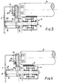
- the conveyor has a frame, which is mainly formed by two parallel longitudinal beams, one of which being shown in the drawing and indicated at 1.
- a series of carrying rollers 2 is mounted between the two frame beams for rotation about parallel axes.
- the way of supporting of the carrying rollers 2 corresponds with that of the well-known conveyors of the type under consideration and will therefore not be described in further detail.
- For the spacing between the successive carrying rollers 2 (which may have a diameter in the order of 50 mm) reference is made to fig. 2.
- This drive belt designates a driving belt which passes under the carrying rollers 2 at one side of the conveyor.
- This drive belt may e.g. be constituted by the upper run of a driven endless belt which is guided, at the ends of the conveyor over guide rollers (not shown in the drawing) and which is kept in a tensioned state by tensioning rollers (neither shown) which are positioned at the lower run of the endless belt.
- the driving belt 3 is supported by a series of pressure rollers 4, the rotating axes of which are each positioned substantially directly under the space between two successive carrying rollers 2 (vide fig. 2).
- the number of pressure rollers 4 is e.g. half the number of carrying rollers 2, so that alternatelya presure roller and no pressure roller respectively is positioned under the successive spaces between the carrying rollers.
- the width of the pressure rollers 4 is a fraction of the length of the carrying rollers 2 and is slightly larger than the width of the driving belt 3.
- the pressure rollers 4 are rotatably mounted on the free end portion of a stationary supporting axle 5 which is extended towards the frame beam 1; the pressure rollers 4 are slightly convex in shape.
- the supporting axles 5 are each supported by a substantially L-shaped support body 6, which has its vertical flange 6a hooked about a support strip 7 fixed to the frame beam 1 and has the free end of its horizontal flange 6b leaning against the innerside of the vertical web 1a of the frame beam 1 and fixed to the latter by means of fastening screws (not shown) which extend through lug-shaped projections 19 of the horizontal flange 6b (vide fig. 2).
- the hollow shaped horizontal flange 6b, supporting the supporting axle 5, is closed at its free end by a thin endwall 8, a circular opening 8a being provided in said wall to support the respective end of the supporting axle 5 with a close fit.
- the small fitness of the endwall 8 allows a certain universal swinging movement of the supporting axle 5 around the center of the opening in said endwall.
- a vertical slot 9 is provided, the width of which corresponds with the diameter of the supporting axle 5. Due to this slot the universal swinging movement allowed by the opening in the endwall 8 is limited to an up and down swinging movement in the vertical plane.
- the vertical flange 6a of the L-shaped body 6 comprises a tubular portion 10 the free end of which is located substantially in the plane of the upper flange 1b of the frame beam 1. At a certain distance from the horizontal flange 6b the tubular portion merges into a widened chamber 11, containing a block 12 of rubber or similar resilient material which is locked in place between the supporting axle 5 and the lower end of the tubular portion 10.
- An adjusting screw 14 extends - with clearance - through the bore 13 of the tubular portion 10 and has its head 15 bearing on the upper end face of the vertical L-flange with the intermediary of a washer 16, whereas the threaded shaft portion 17 of the screw extends through a correspondingly threaded radial bore 18 of the supporting axle 5.
- the adjusting screw 14 By turning the adjusting screw 14 to extend further or less downwardly through the radial bore 18 of the supporting axle 5, the latter may be swung through a slight angle upwardly or downwardly about the centre of the bearing opening 8a.
- the supporting axle 5 is taking a horizontal central position, parallel to the rotating axes of the supporting rollers 2.
- the driving belt 3 is positioned in the central portion of the convex supporting surface of the pressure roller 4 and consequently also takes a horizontal position as seen in the transverse direction.
- the driving belt 3 is shown out of contact with the adjacent supporting rollers 2.
- This case may be illustrative for a conveyor having excentrically journalled supporting rollers (e.g. having an excentricity in the order of 1 mm) at a moment, at which the surface line with the largest radial distance to the supporting roller axis is positioned at the upper side of the roller.
- excentrically journalled supporting rollers e.g. having an excentricity in the order of 1 mm
- At regularly spaced intervals e.g. with a spacing of 4-5 m
- thickenings such as the pad 20 in fig. 2 are provided on the driving belt 3.
- the shown position may also be considered representative of an embodiment with centrically journalled rollers, in which case the respective pressure roller is shown in an inoperative position, caused by a downwardly directed swinging movement.
- the pressure roller mounting on a swingeable supporting axle is also applicable in those cases, in which it must be possible to put a certain section of an accumulating conveyor out of operation, e.g. pneumatically.
Applications Claiming Priority (2)
| Application Number | Priority Date | Filing Date | Title |
|---|---|---|---|
| NL9200958 | 1992-05-31 | ||
| NL9200958A NL9200958A (nl) | 1992-05-31 | 1992-05-31 | Rollentransporteur. |
Publications (2)
| Publication Number | Publication Date |
|---|---|
| EP0573119A1 true EP0573119A1 (fr) | 1993-12-08 |
| EP0573119B1 EP0573119B1 (fr) | 1996-10-30 |
Family
ID=19860865
Family Applications (1)
| Application Number | Title | Priority Date | Filing Date |
|---|---|---|---|
| EP93201559A Expired - Lifetime EP0573119B1 (fr) | 1992-05-31 | 1993-06-01 | Convoyeur à rouleaux |
Country Status (6)
| Country | Link |
|---|---|
| EP (1) | EP0573119B1 (fr) |
| AT (1) | ATE144750T1 (fr) |
| DE (1) | DE69305691T2 (fr) |
| DK (1) | DK0573119T3 (fr) |
| ES (1) | ES2096192T3 (fr) |
| NL (1) | NL9200958A (fr) |
Citations (5)
| Publication number | Priority date | Publication date | Assignee | Title |
|---|---|---|---|---|
| US2001773A (en) * | 1931-04-08 | 1935-05-21 | Lamson Co | Conveyer curve |
| US3176828A (en) * | 1962-11-06 | 1965-04-06 | Alvey Ferguson Co | Accumulating conveyor having skewable rollers |
| US4091916A (en) * | 1976-10-08 | 1978-05-30 | W & H Conveyor Systems, Inc. | Apparatus for driving individual rollers of a power conveyer |
| US4103769A (en) * | 1976-07-06 | 1978-08-01 | Stone Conveyor, Inc. (Entire) | Live roller conveyor |
| FR2614282A1 (fr) * | 1987-04-23 | 1988-10-28 | Daifuku Kk | Transporteur a rouleaux. |
-
1992
- 1992-05-31 NL NL9200958A patent/NL9200958A/nl not_active Application Discontinuation
-
1993
- 1993-06-01 AT AT93201559T patent/ATE144750T1/de not_active IP Right Cessation
- 1993-06-01 DE DE69305691T patent/DE69305691T2/de not_active Expired - Fee Related
- 1993-06-01 DK DK93201559.7T patent/DK0573119T3/da active
- 1993-06-01 ES ES93201559T patent/ES2096192T3/es not_active Expired - Lifetime
- 1993-06-01 EP EP93201559A patent/EP0573119B1/fr not_active Expired - Lifetime
Patent Citations (5)
| Publication number | Priority date | Publication date | Assignee | Title |
|---|---|---|---|---|
| US2001773A (en) * | 1931-04-08 | 1935-05-21 | Lamson Co | Conveyer curve |
| US3176828A (en) * | 1962-11-06 | 1965-04-06 | Alvey Ferguson Co | Accumulating conveyor having skewable rollers |
| US4103769A (en) * | 1976-07-06 | 1978-08-01 | Stone Conveyor, Inc. (Entire) | Live roller conveyor |
| US4091916A (en) * | 1976-10-08 | 1978-05-30 | W & H Conveyor Systems, Inc. | Apparatus for driving individual rollers of a power conveyer |
| FR2614282A1 (fr) * | 1987-04-23 | 1988-10-28 | Daifuku Kk | Transporteur a rouleaux. |
Also Published As
| Publication number | Publication date |
|---|---|
| EP0573119B1 (fr) | 1996-10-30 |
| DE69305691D1 (de) | 1996-12-05 |
| ATE144750T1 (de) | 1996-11-15 |
| NL9200958A (nl) | 1993-12-16 |
| ES2096192T3 (es) | 1997-03-01 |
| DK0573119T3 (fr) | 1997-02-17 |
| DE69305691T2 (de) | 1997-04-03 |
Similar Documents
| Publication | Publication Date | Title |
|---|---|---|
| CA2094373C (fr) | Rouleaux compensateurs pour transporteur a courroie | |
| US3973446A (en) | Web aligner | |
| JP3345090B2 (ja) | 湾曲ベルトコンベア | |
| US6776280B2 (en) | Guidance unit for conveyor belt | |
| CA2028240A1 (fr) | Tendeur de courroie | |
| US5184424A (en) | Self correcting belt tracking apparatus for widebelt abrasive grinding machine | |
| CA2179033A1 (fr) | Dispositif de nettoyage pour transporteur sans fin | |
| US4091916A (en) | Apparatus for driving individual rollers of a power conveyer | |
| US4318468A (en) | Conveyor device | |
| US4187645A (en) | Reactive system for accommodating belt stretch and tracking | |
| US4438617A (en) | Belt tracking and tensioning arrangement | |
| EP0573119B1 (fr) | Convoyeur à rouleaux | |
| CA2364833C (fr) | Transporteur pour cintres | |
| US4435884A (en) | Clip-chain track for tenter clips | |
| US4736498A (en) | Tentering chain guide track for roller-supported tenter clamps | |
| US4164280A (en) | Roller conveyor | |
| CA2067830C (fr) | Dispositif de centrage mecanique automatique pour courroies sans fin sur rouleaux | |
| SU1169903A1 (ru) | Устройство дл центрировани ленты конвейера | |
| AU645150C (en) | Improvements in belt conveyor training idlers | |
| AU645150B2 (en) | Improvements in belt conveyor training idlers | |
| SU1505855A1 (ru) | Устройство дл улавливани ленты конвейера | |
| JPH079823U (ja) | チェーンコンベヤの駆動装置 | |
| SU1102736A1 (ru) | Устройство дл центрировани ленты конвейера | |
| KR0130870Y1 (ko) | 벨트 리턴부 편재이동 조정장치 | |
| GB2074968A (en) | Improvements in or relating to a flexible conveyor belt supporting structure |
Legal Events
| Date | Code | Title | Description |
|---|---|---|---|
| PUAI | Public reference made under article 153(3) epc to a published international application that has entered the european phase |
Free format text: ORIGINAL CODE: 0009012 |
|
| AK | Designated contracting states |
Kind code of ref document: A1 Designated state(s): AT BE CH DE DK ES FR GB GR IE IT LI LU MC NL PT SE |
|
| 17P | Request for examination filed |
Effective date: 19940608 |
|
| GRAG | Despatch of communication of intention to grant |
Free format text: ORIGINAL CODE: EPIDOS AGRA |
|
| 17Q | First examination report despatched |
Effective date: 19960205 |
|
| GRAH | Despatch of communication of intention to grant a patent |
Free format text: ORIGINAL CODE: EPIDOS IGRA |
|
| GRAH | Despatch of communication of intention to grant a patent |
Free format text: ORIGINAL CODE: EPIDOS IGRA |
|
| GRAA | (expected) grant |
Free format text: ORIGINAL CODE: 0009210 |
|
| AK | Designated contracting states |
Kind code of ref document: B1 Designated state(s): AT BE CH DE DK ES FR GB GR IE IT LI LU MC NL PT SE |
|
| PG25 | Lapsed in a contracting state [announced via postgrant information from national office to epo] |
Ref country code: GR Free format text: LAPSE BECAUSE OF FAILURE TO SUBMIT A TRANSLATION OF THE DESCRIPTION OR TO PAY THE FEE WITHIN THE PRESCRIBED TIME-LIMIT Effective date: 19961030 |
|
| REF | Corresponds to: |
Ref document number: 144750 Country of ref document: AT Date of ref document: 19961115 Kind code of ref document: T |
|
| REG | Reference to a national code |
Ref country code: CH Ref legal event code: NV Representative=s name: R. A. EGLI & CO. PATENTANWAELTE |
|
| REF | Corresponds to: |
Ref document number: 69305691 Country of ref document: DE Date of ref document: 19961205 |
|
| REG | Reference to a national code |
Ref country code: IE Ref legal event code: FG4D Free format text: 70478 |
|
| ITF | It: translation for a ep patent filed |
Owner name: MODIANO & ASSOCIATI S.R.L. |
|
| ET | Fr: translation filed | ||
| REG | Reference to a national code |
Ref country code: DK Ref legal event code: T3 |
|
| REG | Reference to a national code |
Ref country code: PT Ref legal event code: SC4A Free format text: AVAILABILITY OF NATIONAL TRANSLATION Effective date: 19961104 |
|
| REG | Reference to a national code |
Ref country code: ES Ref legal event code: FG2A Ref document number: 2096192 Country of ref document: ES Kind code of ref document: T3 |
|
| PLBE | No opposition filed within time limit |
Free format text: ORIGINAL CODE: 0009261 |
|
| STAA | Information on the status of an ep patent application or granted ep patent |
Free format text: STATUS: NO OPPOSITION FILED WITHIN TIME LIMIT |
|
| 26N | No opposition filed | ||
| PG25 | Lapsed in a contracting state [announced via postgrant information from national office to epo] |
Ref country code: MC Effective date: 19971231 |
|
| PGFP | Annual fee paid to national office [announced via postgrant information from national office to epo] |
Ref country code: GB Payment date: 20000523 Year of fee payment: 8 Ref country code: FR Payment date: 20000523 Year of fee payment: 8 Ref country code: SE Payment date: 20000523 Year of fee payment: 8 Ref country code: LU Payment date: 20000523 Year of fee payment: 8 |
|
| PGFP | Annual fee paid to national office [announced via postgrant information from national office to epo] |
Ref country code: PT Payment date: 20000607 Year of fee payment: 8 |
|
| PGFP | Annual fee paid to national office [announced via postgrant information from national office to epo] |
Ref country code: IE Payment date: 20000608 Year of fee payment: 8 |
|
| PGFP | Annual fee paid to national office [announced via postgrant information from national office to epo] |
Ref country code: CH Payment date: 20000609 Year of fee payment: 8 Ref country code: BE Payment date: 20000609 Year of fee payment: 8 |
|
| PGFP | Annual fee paid to national office [announced via postgrant information from national office to epo] |
Ref country code: DE Payment date: 20000612 Year of fee payment: 8 |
|
| PGFP | Annual fee paid to national office [announced via postgrant information from national office to epo] |
Ref country code: ES Payment date: 20000614 Year of fee payment: 8 |
|
| PGFP | Annual fee paid to national office [announced via postgrant information from national office to epo] |
Ref country code: DK Payment date: 20000616 Year of fee payment: 8 |
|
| PGFP | Annual fee paid to national office [announced via postgrant information from national office to epo] |
Ref country code: AT Payment date: 20000620 Year of fee payment: 8 |
|
| PGFP | Annual fee paid to national office [announced via postgrant information from national office to epo] |
Ref country code: NL Payment date: 20000630 Year of fee payment: 8 |
|
| REG | Reference to a national code |
Ref country code: CH Ref legal event code: PUE Owner name: STORK CONVEYOR SYSTEMS B.V. TRANSFER- STORK CSI B. |
|
| NLS | Nl: assignments of ep-patents |
Owner name: STORK CSI B.V. |
|
| REG | Reference to a national code |
Ref country code: GB Ref legal event code: 732E |
|
| REG | Reference to a national code |
Ref country code: PT Ref legal event code: PC4A Free format text: STORK CSI B.V. NL Effective date: 20001023 |
|
| REG | Reference to a national code |
Ref country code: FR Ref legal event code: TP |
|
| PG25 | Lapsed in a contracting state [announced via postgrant information from national office to epo] |
Ref country code: LU Free format text: LAPSE BECAUSE OF NON-PAYMENT OF DUE FEES Effective date: 20010601 Ref country code: IE Free format text: LAPSE BECAUSE OF NON-PAYMENT OF DUE FEES Effective date: 20010601 Ref country code: GB Free format text: LAPSE BECAUSE OF NON-PAYMENT OF DUE FEES Effective date: 20010601 Ref country code: DK Free format text: LAPSE BECAUSE OF NON-PAYMENT OF DUE FEES Effective date: 20010601 Ref country code: AT Free format text: LAPSE BECAUSE OF NON-PAYMENT OF DUE FEES Effective date: 20010601 |
|
| PG25 | Lapsed in a contracting state [announced via postgrant information from national office to epo] |
Ref country code: SE Free format text: LAPSE BECAUSE OF NON-PAYMENT OF DUE FEES Effective date: 20010602 Ref country code: ES Free format text: LAPSE BECAUSE OF NON-PAYMENT OF DUE FEES Effective date: 20010602 |
|
| PG25 | Lapsed in a contracting state [announced via postgrant information from national office to epo] |
Ref country code: LI Free format text: LAPSE BECAUSE OF NON-PAYMENT OF DUE FEES Effective date: 20010630 Ref country code: CH Free format text: LAPSE BECAUSE OF NON-PAYMENT OF DUE FEES Effective date: 20010630 Ref country code: BE Free format text: LAPSE BECAUSE OF NON-PAYMENT OF DUE FEES Effective date: 20010630 |
|
| BERE | Be: lapsed |
Owner name: STORK CSI B.V. Effective date: 20010630 |
|
| PG25 | Lapsed in a contracting state [announced via postgrant information from national office to epo] |
Ref country code: PT Free format text: LAPSE BECAUSE OF NON-PAYMENT OF DUE FEES Effective date: 20011231 |
|
| PG25 | Lapsed in a contracting state [announced via postgrant information from national office to epo] |
Ref country code: NL Free format text: LAPSE BECAUSE OF NON-PAYMENT OF DUE FEES Effective date: 20020101 |
|
| GBPC | Gb: european patent ceased through non-payment of renewal fee |
Effective date: 20010601 |
|
| EUG | Se: european patent has lapsed |
Ref document number: 93201559.7 |
|
| REG | Reference to a national code |
Ref country code: CH Ref legal event code: PL |
|
| PG25 | Lapsed in a contracting state [announced via postgrant information from national office to epo] |
Ref country code: FR Free format text: LAPSE BECAUSE OF NON-PAYMENT OF DUE FEES Effective date: 20020228 |
|
| NLV4 | Nl: lapsed or anulled due to non-payment of the annual fee |
Effective date: 20020101 |
|
| REG | Reference to a national code |
Ref country code: DK Ref legal event code: EBP |
|
| PG25 | Lapsed in a contracting state [announced via postgrant information from national office to epo] |
Ref country code: DE Free format text: LAPSE BECAUSE OF NON-PAYMENT OF DUE FEES Effective date: 20020403 |
|
| REG | Reference to a national code |
Ref country code: PT Ref legal event code: MM4A Free format text: LAPSE DUE TO NON-PAYMENT OF FEES Effective date: 20011231 |
|
| REG | Reference to a national code |
Ref country code: ES Ref legal event code: FD2A Effective date: 20030303 |
|
| PG25 | Lapsed in a contracting state [announced via postgrant information from national office to epo] |
Ref country code: IT Free format text: LAPSE BECAUSE OF NON-PAYMENT OF DUE FEES;WARNING: LAPSES OF ITALIAN PATENTS WITH EFFECTIVE DATE BEFORE 2007 MAY HAVE OCCURRED AT ANY TIME BEFORE 2007. THE CORRECT EFFECTIVE DATE MAY BE DIFFERENT FROM THE ONE RECORDED. Effective date: 20050601 |