EP0572362A1 - Hydraulic apparatus for controlling the raising and lowering of the barrier of a level crossing - Google Patents
Hydraulic apparatus for controlling the raising and lowering of the barrier of a level crossing Download PDFInfo
- Publication number
- EP0572362A1 EP0572362A1 EP93830223A EP93830223A EP0572362A1 EP 0572362 A1 EP0572362 A1 EP 0572362A1 EP 93830223 A EP93830223 A EP 93830223A EP 93830223 A EP93830223 A EP 93830223A EP 0572362 A1 EP0572362 A1 EP 0572362A1
- Authority
- EP
- European Patent Office
- Prior art keywords
- barrier
- cylinder
- equipment
- actuator
- hydraulic
- Prior art date
- Legal status (The legal status is an assumption and is not a legal conclusion. Google has not performed a legal analysis and makes no representation as to the accuracy of the status listed.)
- Granted
Links
Images

Classifications
-
- E—FIXED CONSTRUCTIONS
- E01—CONSTRUCTION OF ROADS, RAILWAYS, OR BRIDGES
- E01F—ADDITIONAL WORK, SUCH AS EQUIPPING ROADS OR THE CONSTRUCTION OF PLATFORMS, HELICOPTER LANDING STAGES, SIGNS, SNOW FENCES, OR THE LIKE
- E01F13/00—Arrangements for obstructing or restricting traffic, e.g. gates, barricades ; Preventing passage of vehicles of selected category or dimensions
- E01F13/04—Arrangements for obstructing or restricting traffic, e.g. gates, barricades ; Preventing passage of vehicles of selected category or dimensions movable to allow or prevent passage
- E01F13/06—Arrangements for obstructing or restricting traffic, e.g. gates, barricades ; Preventing passage of vehicles of selected category or dimensions movable to allow or prevent passage by swinging into open position about a vertical or horizontal axis parallel to the road direction, i.e. swinging gates
Definitions
- the invention relates to improved apparatus for the control of the barriers or bars of level crossings, suitable for providing improved performance, greater safety and improved functioning by comparison with apparatuses which exist at present and are for the most part electro-mechanical.
- the apparatus substantially comprises: a hydraulic power unit capable of actuating a hydraulic cylinder-and-piston actuator for the raising and lowering of the barrier; a hydraulic circuit with distributors, pressure regulators, valves and the like; mechanical locking means at least for the lowered position of the barrier; and auxiliary units for overcoming initial inertia on opening.
- the hydraulic circuit may comprise, as an actuator, a double-acting cylinder-and-piston system, a valve connected in parallel with the cylinder-and-piston system between the circuit branches which feed it; a non-return valve opened by the working pressure of the pump motor group; a directional control valve of the open-and-closed type in the two branches of the supply circuit; and a linkage between the mobile member of the actuator and the angularly mobile equipment of the barrier to be moved.
- the linkage may comprise a sector gear on the mobile equipment of the barrier and a rack on the sliding cylinder forming the mobile member of the actuator.
- the said gear and the said rack may furthermore have flat surfaces which interact with each other in sliding contact to lock the barrier in the lowered position at the end of the corresponding stroke of the actuator.
- counter-weights may be provided to balance the equipment of the barrier, which counter-weights are recessed in a housing for linear sliding and are connected to the said equipment of the barrier by a chain or similar flexible drive, settling gradually on a cam profile.
- a particularly safe arrangement is thus achieved, in that the counter-weights do not project externally and hence cannot constitute a potential risk to persons as occurs in the apparatuses which are currently known.
- 1 generally indicates a supporting frame which can be enclosed in a protective hood 2 from which limited parts project and in which access ports are provided for inspections and maintenance.
- a protective hood 2 On the frame 1 are provided supports 1a for a horizontal shaft 3 which rotates with the barrier complex generally designated A.
- the gear 7 is a sector of a circle on which a chain 10, anchored at 12 on the upper end of the said gear 7, can settle;
- the gear 9, by contrast, is shaped in the form of a variable-radius cam, and a chain 14 anchored at 16 on the end of the cam profile of the said gear 9 can settle thereon.
- the chain 10 is deflected by a deflection pulley 18 towards a hollow cylinder 20 into which it penetrates, reaching and anchoring itself on a lower plug 22 which is able to slide in-the said cylinder 20; a large helical spring 24 acts upon the plug 22, which surrounds the chain 10 and acts against the upper closed end 20A of the cylinder 20.
- the chain 14 is in turn deflected by a pulley 28 and by a second pulley 30 in order to reach and anchor itself on the end 32A of a rod 32 which passes through a plurality of counter-weights 34 - which are, for example, discoidal or equivalent - which are stacked and supported by the rod and can be adjusted in number, and hence in total weight, in order to balance the mobile equipment around and with the shaft 3, and which comprises the barrier A and the gears 7 and 9.
- the chain 14, instead of being continuous in order to reach the counter-weights 34 may be interrupted by a speed change means replacing the deflection pulley 28 or the deflection pulley 30, in order to reduce the bulk and load of the weights 34.
- This actuator designates an assembly with a hydraulic pump and motor for a power unit which serves to supply a double-acting hydraulic actuator.
- This actuator comprises a cylinder-and-piston system with a rod 42 to which is solidly fixed a piston 44 which remains stationary while the cylinder 46 is slidable; in the drawing, the said actuator 42, 44, 46 is arranged in the vertical attitude.
- Solidly fixed to the cylinder 46 which represents the mobile member of the cylinder-and-piston system, is a rack 50 which is followed by a flattened zone 52; see in particular Fig. 5.
- On the shaft 3 and solidly fixed thereto is provided a discoidal body 54 having a sector gear 54A followed by a flattened zone 56.
- the mobile equipment 46 of the cylinder of the hydraulic actuator also forms a pair of racks 60, opposite to the rack 50 and capable of engaging with corresponding sector gears 62, which are articulated at 64 and on which there acts - via a crosspiece 66 - a large compression spring 78, expediently sheathed, to oscillate about the axis of the crosspiece and via a fixed articulation 70.
- the sector gear 62 like the sector gear 54A, also has a flattened part 72, with which there can interact a flattened part 74 which is formed in the mobile part 46 of the cylinder of the actuator 42, 44, 46 in alignment with the rack 60, similarly to the flattened part 52 which is aligned with the rack 50 of the mobile cylinder 46.
- the displacement of the mobile cylinder 46 brought about by the cylinder-and-piston system 42, 44, 46 causes rotation of the mobile equipment of the barrier A comprising the shaft 3, the gear 54A and the gears 7 and 9, until mutual engagement takes place between the rack 50 and the gear 54A; beyond a certain limit of the lifting of the cylinder 46, the flattened part 56 of the body 54 enters into sliding contact with the flattened part 52 of the mobile cylinder 46, fixing the position reached by the said mobile equipment and hence by the barrier A in the horizontal position.
- the sector gear 62 engaging with the rack 60, causes a rotation of the gear 62 when the toothings of the gear 62 and of the rack 60 are engaged, while it frees the gear 62 when the flattened part 72 thereof enters into sliding contact with the flattened part 74 of the cylinder 46.
- the cylinder 46 In the position shown in Fig. 5, the cylinder 46 is in the position of maximum elevation and the bar A is lowered, that is to say horizontal; when it is caused to move downwards, that is to say in the direction of the arrow fB, the cylinder 46 initially causes merely the rotation, in a clockwise direction as shown in Figs.
- the spring 24 tends to re-expand, having cooperated in the initial lifting displacement of the barrier A, when the force resisting the lifting is maximum for the horizontal position of the said barrier A; the effect of the spring 24 is attenuated as the lifting progresses; at this time, however, the force resisting the lifting of the barrier is reduced by the gradually increased inclination of the barrier relative to the horizontal.
- the system of counter-weights 34 also cooperates in overcoming the initial load, these acting with a constant load on the chain 14 and hence on the gear 9 with the cam profile, producing, as regards the mobile equipment, an initial assistance which is relatively very powerful as a result of the high leverage created between the profile of the gear 9 and the axis of the shaft 3; this effect is gradually attenuated as the barrier A rises and hence as the equipment thereof rotates about the axis of the shafts 3, as a result of the gradual reduction of the radius of action of the chain 14 at its tangent point relative to the profile of the gear 9.
- the engagement between the rack 60 and the sector gear 72 produces a rotation of the gear 72 and hence a compressive loading of the spring 68, which constitutes an energy accumulation- system which is stabilised, as the lowering of the cylinder 46 continues, by the effect of the locking of the gear 62 brought about by the flattened surfaces 72 and 74 which are coupled and which slide relative to each other, keeping the loading of the spring 78 stabilised; only at the end of the lowering of the barrier A to the horizontal, and hence only towards the end of the lifting of the cylinder 46 by the actuator 42, 44, 46, does the overloaded spring 68 intervene, completing the lifting of the cylinder 46 by means of the toothings 62 and 60 and coupling the surfaces 52 and 56 in order to bring about the locking of the lowered barrier A; the spring 68 has the purpose of moving the cylinder 46 to the end of its stroke once the barrier A is lowered into the horizontal position to achieve the blocking of any exchange.
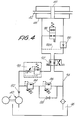
- Fig. 4 The hydraulic circuit for controlling the actuator 42, 44, 46 responsible for the movement of the barrier A, is illustrated in Fig. 4, in which the motor/pump unit 40 and the actuator 42, 44, 46 are illustrated diagrammatically.
- 82 designates a non-return valve and 84 and 86 designate pressure regulating valves, the valve 86 being capable of being excluded, if desired, by means a tap 88 which, when opened, bypasses the valve 86 causing the valve 84 to work alone, whereas closure of the tap 88 causes the additional activation of the regulator valve 86, which then operates in series with the valve 84.
- 90 designates a regulator of flow, and hence of the speed of the displacements of the actuator and of the equipment of the barrier.
- valve 92 designates a directional control valve for switching the displacements, in one direction or the other, of the mobile equipment, that is to say of the cylinder 46 of the actuator 42, 44, 46: the valve 92 switches the delivery from the pump through the regulator 90 and the outflow 94, towards the reservoir 96.
- the valve 98 which is closed during normal operation, opens in the absence of current, enabling the counter-weights to move the bar into the position required by the project, without passive resistance caused by hydraulic loading.
- the valve 100 retains the oil in the line and hence locks the barrier: it opens only in the presence of a hydraulic command of opposite sign.
Abstract
Description
- The invention relates to improved apparatus for the control of the barriers or bars of level crossings, suitable for providing improved performance, greater safety and improved functioning by comparison with apparatuses which exist at present and are for the most part electro-mechanical. The objects and advantages of the invention will become apparent from the text which follows.
- The apparatus substantially comprises: a hydraulic power unit capable of actuating a hydraulic cylinder-and-piston actuator for the raising and lowering of the barrier; a hydraulic circuit with distributors, pressure regulators, valves and the like; mechanical locking means at least for the lowered position of the barrier; and auxiliary units for overcoming initial inertia on opening.
- The hydraulic circuit may comprise, as an actuator, a double-acting cylinder-and-piston system, a valve connected in parallel with the cylinder-and-piston system between the circuit branches which feed it; a non-return valve opened by the working pressure of the pump motor group; a directional control valve of the open-and-closed type in the two branches of the supply circuit; and a linkage between the mobile member of the actuator and the angularly mobile equipment of the barrier to be moved.
- The linkage may comprise a sector gear on the mobile equipment of the barrier and a rack on the sliding cylinder forming the mobile member of the actuator. The said gear and the said rack may furthermore have flat surfaces which interact with each other in sliding contact to lock the barrier in the lowered position at the end of the corresponding stroke of the actuator.
- Other features are defined in the sub-claims following the description. In particular, counter-weights may be provided to balance the equipment of the barrier, which counter-weights are recessed in a housing for linear sliding and are connected to the said equipment of the barrier by a chain or similar flexible drive, settling gradually on a cam profile. A particularly safe arrangement is thus achieved, in that the counter-weights do not project externally and hence cannot constitute a potential risk to persons as occurs in the apparatuses which are currently known.
- The invention will be better understood by studying the description and the attached drawing which shows a practical, non-limiting embodiment of the said invention. In the drawing:
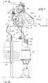
- Fig. 1 shows an external view of a method of embodiment;
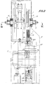
- Fig. 2 shows a view along the line II-II in Fig. 1;
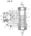
- Fig. 3 shows a horizontal section substantially along the line III-III in Fig. 2;
- Fig. 4 shows a diagram of the hydraulic plant; and
- Fig. 5 shows an enlarged detail of Fig. 1.
- In accordance with what is shown in the attached drawing, 1 generally indicates a supporting frame which can be enclosed in a protective hood 2 from which limited parts project and in which access ports are provided for inspections and maintenance. On the
frame 1 are provided supports 1a for ahorizontal shaft 3 which rotates with the barrier complex generally designated A. Provided on theshaft 3 and coupled thereto is ahub 5 to which twosector gears gear 7 is a sector of a circle on which achain 10, anchored at 12 on the upper end of the saidgear 7, can settle; thegear 9, by contrast, is shaped in the form of a variable-radius cam, and achain 14 anchored at 16 on the end of the cam profile of the saidgear 9 can settle thereon. Thechain 10 is deflected by adeflection pulley 18 towards ahollow cylinder 20 into which it penetrates, reaching and anchoring itself on a lower plug 22 which is able to slide in-the saidcylinder 20; a largehelical spring 24 acts upon the plug 22, which surrounds thechain 10 and acts against the upper closedend 20A of thecylinder 20. Thechain 14 is in turn deflected by apulley 28 and by asecond pulley 30 in order to reach and anchor itself on theend 32A of arod 32 which passes through a plurality of counter-weights 34 - which are, for example, discoidal or equivalent - which are stacked and supported by the rod and can be adjusted in number, and hence in total weight, in order to balance the mobile equipment around and with theshaft 3, and which comprises the barrier A and thegears chain 14, instead of being continuous in order to reach thecounter-weights 34, may be interrupted by a speed change means replacing thedeflection pulley 28 or thedeflection pulley 30, in order to reduce the bulk and load of theweights 34. The objects of the two balancing systems will now be specified in more detail. - 40 designates an assembly with a hydraulic pump and motor for a power unit which serves to supply a double-acting hydraulic actuator. This actuator comprises a cylinder-and-piston system with a
rod 42 to which is solidly fixed apiston 44 which remains stationary while thecylinder 46 is slidable; in the drawing, the saidactuator cylinder 46, which represents the mobile member of the cylinder-and-piston system, is arack 50 which is followed by aflattened zone 52; see in particular Fig. 5. On theshaft 3 and solidly fixed thereto is provided adiscoidal body 54 having asector gear 54A followed by aflattened zone 56. The function of this arrangement of therack 50 and of thetoothing 54A is, with thehydraulic actuator sector 54A and hence of the mobile equipment about the axis of theshaft 3 and with theshaft 3 and which comprises thesector gears shaft 3 and is mobile angularly therewith. At the end of the upward stroke of thecylinder 46, the twoflat surfaces - The
mobile equipment 46 of the cylinder of the hydraulic actuator also forms a pair ofracks 60, opposite to therack 50 and capable of engaging withcorresponding sector gears 62, which are articulated at 64 and on which there acts - via a crosspiece 66 - a large compression spring 78, expediently sheathed, to oscillate about the axis of the crosspiece and via afixed articulation 70. Thesector gear 62, like thesector gear 54A, also has aflattened part 72, with which there can interact aflattened part 74 which is formed in themobile part 46 of the cylinder of theactuator rack 60, similarly to theflattened part 52 which is aligned with therack 50 of themobile cylinder 46. - The displacement of the
mobile cylinder 46 brought about by the cylinder-and-piston system shaft 3, thegear 54A and thegears rack 50 and thegear 54A; beyond a certain limit of the lifting of thecylinder 46, theflattened part 56 of thebody 54 enters into sliding contact with theflattened part 52 of themobile cylinder 46, fixing the position reached by the said mobile equipment and hence by the barrier A in the horizontal position. Similarly, thesector gear 62, engaging with therack 60, causes a rotation of thegear 62 when the toothings of thegear 62 and of therack 60 are engaged, while it frees thegear 62 when theflattened part 72 thereof enters into sliding contact with theflattened part 74 of thecylinder 46. In the position shown in Fig. 5, thecylinder 46 is in the position of maximum elevation and the bar A is lowered, that is to say horizontal; when it is caused to move downwards, that is to say in the direction of the arrow fB, thecylinder 46 initially causes merely the rotation, in a clockwise direction as shown in Figs. 1 and 5, of thegear 62 and hence causes a loading of thespring 68 until, after the first part of the downward stroke of thecylinder 46, theflattened surfaces assembly spring 68. During the first initial part of the downward stroke of thecylinder 46, there also take place a sliding of thesurface 52 on thesurface 56 and an unchanged retention of the angular position of the equipment leading to theshaft 3 and comprising the barrier A; immediately afterwards, engagement commences between therack 50 and thesector gear 54A, and this initiates the rotation - in the anticlockwise direction, as shown in Figs. 1 and 5 - of the equipment of theshaft 3, of thegears shaft 3. At the start of the angular lifting movement of the barrier A, in the anticlockwise direction as seen in Fig. 1 and Fig. 5, thechain 10 is in the position of maximum upward pressure caused by thegear 7 and hence thespring 24 is in a state of maximum loading by compression; as the barrier A rises, that is to say as the equipment of the barrier and of theshaft 3 rotates in the anticlockwise direction as seen in Figs. 1 and 5, thespring 24 tends to re-expand, having cooperated in the initial lifting displacement of the barrier A, when the force resisting the lifting is maximum for the horizontal position of the said barrier A; the effect of thespring 24 is attenuated as the lifting progresses; at this time, however, the force resisting the lifting of the barrier is reduced by the gradually increased inclination of the barrier relative to the horizontal. At the start of the lifting of the barrier A and of its equipment the system ofcounter-weights 34 also cooperates in overcoming the initial load, these acting with a constant load on thechain 14 and hence on thegear 9 with the cam profile, producing, as regards the mobile equipment, an initial assistance which is relatively very powerful as a result of the high leverage created between the profile of thegear 9 and the axis of theshaft 3; this effect is gradually attenuated as the barrier A rises and hence as the equipment thereof rotates about the axis of theshafts 3, as a result of the gradual reduction of the radius of action of thechain 14 at its tangent point relative to the profile of thegear 9. - At the start of the lowering of the
cylinder 46, the engagement between therack 60 and thesector gear 72 produces a rotation of thegear 72 and hence a compressive loading of thespring 68, which constitutes an energy accumulation- system which is stabilised, as the lowering of thecylinder 46 continues, by the effect of the locking of thegear 62 brought about by theflattened surfaces cylinder 46 by theactuator overloaded spring 68 intervene, completing the lifting of thecylinder 46 by means of thetoothings surfaces spring 68 has the purpose of moving thecylinder 46 to the end of its stroke once the barrier A is lowered into the horizontal position to achieve the blocking of any exchange. - The hydraulic circuit for controlling the
actuator pump unit 40 and theactuator valve 86 being capable of being excluded, if desired, by means atap 88 which, when opened, bypasses thevalve 86 causing thevalve 84 to work alone, whereas closure of thetap 88 causes the additional activation of theregulator valve 86, which then operates in series with thevalve 84. 90 designates a regulator of flow, and hence of the speed of the displacements of the actuator and of the equipment of the barrier. 92 designates a directional control valve for switching the displacements, in one direction or the other, of the mobile equipment, that is to say of thecylinder 46 of theactuator valve 92 switches the delivery from the pump through theregulator 90 and theoutflow 94, towards thereservoir 96. Thevalve 98, which is closed during normal operation, opens in the absence of current, enabling the counter-weights to move the bar into the position required by the project, without passive resistance caused by hydraulic loading. Thevalve 100 retains the oil in the line and hence locks the barrier: it opens only in the presence of a hydraulic command of opposite sign. - The reason for this selection is that mechanical locking of the lowered barrier is required while, depending on the type of level crossing, it may be desirable to keep the barrier raised or to lower it by gravity in the event of absence of current.
- In any event, when the barrier is raised, a locking is desired, which cannot be mechanical, given that the barrier must be released if the electrical supply fails.
- It is understood that the drawing shows only an example of embodiment, given solely by way of a practical demonstration of the invention, it being possible for the said invention to vary in forms and arrangements without thereby departing from the scope of the idea which underlies the said invention. The presence of any reference numbers in the appended claims has the purpose of facilitating reading of the claims with reference to the description and to the drawing, and does not restrict the scope of the protection represented by the claims.
Claims (10)
- Apparatus for controlling the raising and lowering of the barrier of a level crossing, characterised in that it comprises: a hydraulic power unit (40) capable of actuating a hydraulic cylinder-and-piston actuator (46, 42) for the raising and lowering of the barrier (A); a hydraulic circuit with distributors, pressure regulators, valves and the like; mechanical locking means (52, 56) at least for the lowered position of the barrier (A); and auxiliary units (7, 10; 9, 14) for overcoming initial inertia on opening.
- Apparatus according to Claim 1, characterised in that the hydraulic circuit comprises, as an actuator, a double-acting cylinder-and-piston system (46, 44, 42); a valve (92) connected in parallel on the two branches of the supply circuit leaving to the cylinder-and-piston system; and a linkage (50, 54A) between the mobile member (46) of the actuator and the angularly mobile equipment of the barrier (A) to be moved.
- Apparatus according to at least Claim 2, characterised in that it comprises a valve (98) which establishes communication between the two volumes of the cylinder (46) of the cylinder-and-piston system (46, 44, 42), the said valve being closed in normal operating conditions and opening in the event of lack of electrical supply, in order to lock the barrier (A) and to permit the latter to reach a predetermined design position under the effect of its own weight and the counter-weight.
- Apparatus according to Claim 3, characterised in that a valve (100) is arranged in one branch of the supply circuit of the cylinder-and-piston system (46, 44, 42) and closes the said line, keeping the barrier locked, the said valve opening only as a result of a hydraulic pressure of sign such as to cause lifting of the barrier (A).
- Apparatus according to Claim 2, 3, or 4, characterised in that the said linkage comprises a sector gear (54A) on the mobile equipment of the barrier (A) and a rack (50) on the slidable cylinder (46) constituting the mobile member of the actuator.
- Apparatus according to Claim 5, characterised in that the said gear (54A) and the said rack (50) have flat surfaces (56, 52) which interact mutually with sliding contact in order to lock the barrier (A) in the lowered position at the end of the corresponding stroke of the actuator.
- Apparatus according to one or more of the proceeding claims, characterised in that it comprises a spring (68) which is loaded at the start of opening by a sector gear (62), is kept loaded - by means of interacting flat surfaces (72, 74) - during the opening and closing strokes, and is capable of completing the closure stroke.
- Apparatus according to one or more of the preceding claims, characterised in that the equipment of the barrier (A) also comprises a gear (7) for a chain or other flexible connector (10) interacting with an auxiliary compression spring (24) which acts on the equipment of the barrier at the start of the lifting stroke for the purpose of opening, the said auxiliary spring (24) being reloaded during the lowering of the barrier (A), having a balancing function.
- Apparatus according to one or more of the preceding claims, characterised in that it comprises counter-weights (34) to balance the equipment of the barrier, which counterweights are recessed in a housing for linear sliding and are connected to the said equipment of the barrier (A) by a chain or similar flexible drive (14), settling gradually on a cam profile (9) of variable radius, solidly fixed to the said equipment.
- Hydraulic apparatus for controlling the raising and lowering of the barrier of a level crossing; all as described and illustrated by way of example in the attached drawing.
Applications Claiming Priority (2)
| Application Number | Priority Date | Filing Date | Title |
|---|---|---|---|
| ITFI920116 | 1992-05-28 | ||
| ITFI920116A IT1258735B (en) | 1992-05-28 | 1992-05-28 | HYDRAULIC CONTROL EQUIPMENT FOR LIFTING AND LOWERING THE AUCTION OF A LEVEL PASSAGE |
Publications (2)
| Publication Number | Publication Date |
|---|---|
| EP0572362A1 true EP0572362A1 (en) | 1993-12-01 |
| EP0572362B1 EP0572362B1 (en) | 1996-08-28 |
Family
ID=11350110
Family Applications (1)
| Application Number | Title | Priority Date | Filing Date |
|---|---|---|---|
| EP93830223A Expired - Lifetime EP0572362B1 (en) | 1992-05-28 | 1993-05-25 | Hydraulic apparatus for controlling the raising and lowering of the barrier of a level crossing |
Country Status (7)
| Country | Link |
|---|---|
| EP (1) | EP0572362B1 (en) |
| AT (1) | ATE141978T1 (en) |
| DE (1) | DE69304256T2 (en) |
| DK (1) | DK0572362T3 (en) |
| ES (1) | ES2090942T3 (en) |
| GR (1) | GR3020904T3 (en) |
| IT (1) | IT1258735B (en) |
Cited By (4)
| Publication number | Priority date | Publication date | Assignee | Title |
|---|---|---|---|---|
| CN102518055A (en) * | 2011-12-06 | 2012-06-27 | 中国核电工程有限公司 | High-strength anti-crash device |
| WO2014172311A3 (en) * | 2013-04-18 | 2015-03-26 | Siemens Industry, Inc. | User configurable horizontal brake feature for railroad crossing gates |
| CN107705698A (en) * | 2017-08-08 | 2018-02-16 | 广西南宁东能建筑工程技术有限公司 | A kind of novel traffic indication plate |
| CN107784925A (en) * | 2017-08-08 | 2018-03-09 | 广西南宁东能建筑工程技术有限公司 | A kind of modified traffic indication board device |
Citations (6)
| Publication number | Priority date | Publication date | Assignee | Title |
|---|---|---|---|---|
| US1412878A (en) * | 1917-09-22 | 1922-04-18 | Nat Pneumatic Co | Fluid-pressure-actuated motor |
| FR2289984A1 (en) * | 1974-10-31 | 1976-05-28 | Doernemann Carola | TRAFFIC GUIDANCE INSTALLATION |
| US4133140A (en) * | 1975-11-14 | 1979-01-09 | Devices Development Corporation | Safety mechanism for highway exit ramp |
| EP0422710A1 (en) * | 1989-10-13 | 1991-04-17 | FAAC S.p.A. | Bar gate device with symmetrical actuator |
| FR2669075A1 (en) * | 1990-11-09 | 1992-05-15 | Ero Automatisme | Actuating device for automatic barrier |
| EP0487755A1 (en) * | 1990-11-26 | 1992-06-03 | Scheidt & Bachmann Gmbh | Electrohydraulical gate control |
-
1992
- 1992-05-28 IT ITFI920116A patent/IT1258735B/en active IP Right Grant
-
1993
- 1993-05-25 DK DK93830223.9T patent/DK0572362T3/en active
- 1993-05-25 ES ES93830223T patent/ES2090942T3/en not_active Expired - Lifetime
- 1993-05-25 DE DE69304256T patent/DE69304256T2/en not_active Expired - Lifetime
- 1993-05-25 EP EP93830223A patent/EP0572362B1/en not_active Expired - Lifetime
- 1993-05-25 AT AT93830223T patent/ATE141978T1/en active
-
1996
- 1996-08-29 GR GR960402130T patent/GR3020904T3/en unknown
Patent Citations (6)
| Publication number | Priority date | Publication date | Assignee | Title |
|---|---|---|---|---|
| US1412878A (en) * | 1917-09-22 | 1922-04-18 | Nat Pneumatic Co | Fluid-pressure-actuated motor |
| FR2289984A1 (en) * | 1974-10-31 | 1976-05-28 | Doernemann Carola | TRAFFIC GUIDANCE INSTALLATION |
| US4133140A (en) * | 1975-11-14 | 1979-01-09 | Devices Development Corporation | Safety mechanism for highway exit ramp |
| EP0422710A1 (en) * | 1989-10-13 | 1991-04-17 | FAAC S.p.A. | Bar gate device with symmetrical actuator |
| FR2669075A1 (en) * | 1990-11-09 | 1992-05-15 | Ero Automatisme | Actuating device for automatic barrier |
| EP0487755A1 (en) * | 1990-11-26 | 1992-06-03 | Scheidt & Bachmann Gmbh | Electrohydraulical gate control |
Cited By (7)
| Publication number | Priority date | Publication date | Assignee | Title |
|---|---|---|---|---|
| CN102518055A (en) * | 2011-12-06 | 2012-06-27 | 中国核电工程有限公司 | High-strength anti-crash device |
| WO2014172311A3 (en) * | 2013-04-18 | 2015-03-26 | Siemens Industry, Inc. | User configurable horizontal brake feature for railroad crossing gates |
| US9272721B2 (en) | 2013-04-18 | 2016-03-01 | Siemens Industry, Inc. | User configurable horizontal brake feature for railroad crossing gates |
| CN107705698A (en) * | 2017-08-08 | 2018-02-16 | 广西南宁东能建筑工程技术有限公司 | A kind of novel traffic indication plate |
| CN107784925A (en) * | 2017-08-08 | 2018-03-09 | 广西南宁东能建筑工程技术有限公司 | A kind of modified traffic indication board device |
| CN107705698B (en) * | 2017-08-08 | 2019-09-03 | 台州中海道路设施有限公司 | A kind of traffic sign device |
| CN107784925B (en) * | 2017-08-08 | 2019-11-15 | 湖北工业大学 | A kind of traffic sign device |
Also Published As
| Publication number | Publication date |
|---|---|
| ES2090942T3 (en) | 1996-10-16 |
| EP0572362B1 (en) | 1996-08-28 |
| DE69304256D1 (en) | 1996-10-02 |
| ITFI920116A0 (en) | 1992-05-28 |
| ITFI920116A1 (en) | 1993-11-28 |
| GR3020904T3 (en) | 1996-11-30 |
| DK0572362T3 (en) | 1996-09-16 |
| ATE141978T1 (en) | 1996-09-15 |
| IT1258735B (en) | 1996-02-27 |
| DE69304256T2 (en) | 1997-02-06 |
Similar Documents
| Publication | Publication Date | Title |
|---|---|---|
| US4490068A (en) | Hydraulic safety barrier traffic-way controller | |
| EP0566203B1 (en) | Device with synchronous hydraulic jacks | |
| US5016767A (en) | Boom articulation mechanism with, simultaneously operable, cylinders | |
| EP0572362B1 (en) | Hydraulic apparatus for controlling the raising and lowering of the barrier of a level crossing | |
| EP3737633B1 (en) | Hydraulic lift structure with vertical lifting movement for motor vehicles and similar vehicles | |
| US8152407B1 (en) | Auxiliary pressure relief reservoir for crash barrier | |
| WO2001027499A1 (en) | Low-level lift | |
| US6009670A (en) | Gate operator for vertical gate movement | |
| KR20000039494A (en) | Hydraulic elevator device | |
| EP3497338A1 (en) | Hydraulic, in particular pressure-accumulator-free, drive arrangement for and comprising a consumer, in particular for presses, and method for operating a hydraulic drive arrangement of said type | |
| US8360678B2 (en) | Crash barrier with over-pressure relief system | |
| EP1932797A1 (en) | Lifting apparatus | |
| US5351440A (en) | Vertical lift device | |
| EP2655232B1 (en) | Elevator system having a double-decker | |
| EP0582332B1 (en) | Positive-action device for bringing about the rotary movement of a hatch with secure locking thereof in the open position | |
| US4759262A (en) | Apparatus for restraining rotary motion of a motor component | |
| WO1995019313A1 (en) | Automatic loading bucket elevator | |
| US7331435B2 (en) | Continuously blockable arresting device | |
| SU1654212A1 (en) | Nine hoist drive | |
| DE4302928A1 (en) | Synchronised motion control of hydraulic linear actuators | |
| AU590317B2 (en) | Hydraulic control unit | |
| DE4131821C1 (en) | Pressure medium safety circuit for boiler lid handling - has extra safety valve coupled to valve system for switching in dependence on pressure threshold value | |
| RU2570679C1 (en) | Hydraulic drive mainly used for mobile antenna unit with lifting element | |
| SU1455069A1 (en) | Hydraulic drive | |
| DE1238170B (en) | Device for securing against exceeding the permissible load torque for cranes with jibs |
Legal Events
| Date | Code | Title | Description |
|---|---|---|---|
| PUAI | Public reference made under article 153(3) epc to a published international application that has entered the european phase |
Free format text: ORIGINAL CODE: 0009012 |
|
| AK | Designated contracting states |
Kind code of ref document: A1 Designated state(s): AT BE CH DE DK ES FR GB GR IE LI LU MC NL PT SE |
|
| 17P | Request for examination filed |
Effective date: 19940305 |
|
| 17Q | First examination report despatched |
Effective date: 19950509 |
|
| GRAH | Despatch of communication of intention to grant a patent |
Free format text: ORIGINAL CODE: EPIDOS IGRA |
|
| GRAH | Despatch of communication of intention to grant a patent |
Free format text: ORIGINAL CODE: EPIDOS IGRA |
|
| GRAA | (expected) grant |
Free format text: ORIGINAL CODE: 0009210 |
|
| AK | Designated contracting states |
Kind code of ref document: B1 Designated state(s): AT BE CH DE DK ES FR GB GR IE LI LU MC NL PT SE |
|
| PG25 | Lapsed in a contracting state [announced via postgrant information from national office to epo] |
Ref country code: GR Free format text: LAPSE BECAUSE OF FAILURE TO SUBMIT A TRANSLATION OF THE DESCRIPTION OR TO PAY THE FEE WITHIN THE PRESCRIBED TIME-LIMIT Effective date: 19960828 |
|
| REF | Corresponds to: |
Ref document number: 141978 Country of ref document: AT Date of ref document: 19960915 Kind code of ref document: T |
|
| REG | Reference to a national code |
Ref country code: CH Ref legal event code: NV Representative=s name: DIPL.-ING. ETH H. R. WERFFELI PATENTANWALT |
|
| REG | Reference to a national code |
Ref country code: DK Ref legal event code: T3 |
|
| REF | Corresponds to: |
Ref document number: 69304256 Country of ref document: DE Date of ref document: 19961002 |
|
| REG | Reference to a national code |
Ref country code: IE Ref legal event code: FG4D Free format text: 69603 |
|
| REG | Reference to a national code |
Ref country code: ES Ref legal event code: FG2A Ref document number: 2090942 Country of ref document: ES Kind code of ref document: T3 |
|
| ET | Fr: translation filed | ||
| REG | Reference to a national code |
Ref country code: GR Ref legal event code: FG4A Free format text: 3020904 |
|
| REG | Reference to a national code |
Ref country code: ES Ref legal event code: FG2A Ref document number: 2090942 Country of ref document: ES Kind code of ref document: T3 |
|
| REG | Reference to a national code |
Ref country code: PT Ref legal event code: SC4A Free format text: AVAILABILITY OF NATIONAL TRANSLATION Effective date: 19961017 |
|
| PG25 | Lapsed in a contracting state [announced via postgrant information from national office to epo] |
Ref country code: IE Free format text: LAPSE BECAUSE OF NON-PAYMENT OF DUE FEES Effective date: 19970525 Ref country code: DK Free format text: LAPSE BECAUSE OF NON-PAYMENT OF DUE FEES Effective date: 19970525 |
|
| REG | Reference to a national code |
Ref country code: DK Ref legal event code: EBP |
|
| PG25 | Lapsed in a contracting state [announced via postgrant information from national office to epo] |
Ref country code: LU Free format text: LAPSE BECAUSE OF NON-PAYMENT OF DUE FEES Effective date: 19970531 Ref country code: LI Free format text: LAPSE BECAUSE OF NON-PAYMENT OF DUE FEES Effective date: 19970531 Ref country code: CH Free format text: LAPSE BECAUSE OF NON-PAYMENT OF DUE FEES Effective date: 19970531 |
|
| PLBE | No opposition filed within time limit |
Free format text: ORIGINAL CODE: 0009261 |
|
| STAA | Information on the status of an ep patent application or granted ep patent |
Free format text: STATUS: NO OPPOSITION FILED WITHIN TIME LIMIT |
|
| 26N | No opposition filed | ||
| PG25 | Lapsed in a contracting state [announced via postgrant information from national office to epo] |
Ref country code: PT Effective date: 19971130 Ref country code: MC Effective date: 19971130 |
|
| PG25 | Lapsed in a contracting state [announced via postgrant information from national office to epo] |
Ref country code: NL Effective date: 19971201 |
|
| REG | Reference to a national code |
Ref country code: GR Ref legal event code: MM2A Free format text: 3020904 |
|
| REG | Reference to a national code |
Ref country code: CH Ref legal event code: PL |
|
| NLV4 | Nl: lapsed or anulled due to non-payment of the annual fee |
Effective date: 19971201 |
|
| REG | Reference to a national code |
Ref country code: PT Ref legal event code: MM4A Free format text: LAPSE DUE TO NON-PAYMENT OF FEES Effective date: 19971130 |
|
| REG | Reference to a national code |
Ref country code: GB Ref legal event code: IF02 |
|
| PGFP | Annual fee paid to national office [announced via postgrant information from national office to epo] |
Ref country code: SE Payment date: 20120524 Year of fee payment: 20 Ref country code: BE Payment date: 20120531 Year of fee payment: 20 Ref country code: FR Payment date: 20120530 Year of fee payment: 20 Ref country code: GB Payment date: 20120420 Year of fee payment: 20 |
|
| PGFP | Annual fee paid to national office [announced via postgrant information from national office to epo] |
Ref country code: DE Payment date: 20120724 Year of fee payment: 20 Ref country code: ES Payment date: 20120521 Year of fee payment: 20 |
|
| PGFP | Annual fee paid to national office [announced via postgrant information from national office to epo] |
Ref country code: AT Payment date: 20120504 Year of fee payment: 20 |
|
| REG | Reference to a national code |
Ref country code: DE Ref legal event code: R071 Ref document number: 69304256 Country of ref document: DE |
|
| BE20 | Be: patent expired |
Owner name: *ANGIOLO SILIANI S.P.A. Effective date: 20130525 |
|
| REG | Reference to a national code |
Ref country code: GB Ref legal event code: PE20 Expiry date: 20130524 |
|
| REG | Reference to a national code |
Ref country code: AT Ref legal event code: MK07 Ref document number: 141978 Country of ref document: AT Kind code of ref document: T Effective date: 20130525 |
|
| PG25 | Lapsed in a contracting state [announced via postgrant information from national office to epo] |
Ref country code: DE Free format text: LAPSE BECAUSE OF EXPIRATION OF PROTECTION Effective date: 20130528 Ref country code: GB Free format text: LAPSE BECAUSE OF EXPIRATION OF PROTECTION Effective date: 20130524 |
|
| REG | Reference to a national code |
Ref country code: ES Ref legal event code: FD2A Effective date: 20130807 |
|
| PG25 | Lapsed in a contracting state [announced via postgrant information from national office to epo] |
Ref country code: ES Free format text: LAPSE BECAUSE OF EXPIRATION OF PROTECTION Effective date: 20130526 |