EP0572333A1 - Klappenventil mit verbesserter Dichtmanschette - Google Patents
Klappenventil mit verbesserter Dichtmanschette Download PDFInfo
- Publication number
- EP0572333A1 EP0572333A1 EP93420205A EP93420205A EP0572333A1 EP 0572333 A1 EP0572333 A1 EP 0572333A1 EP 93420205 A EP93420205 A EP 93420205A EP 93420205 A EP93420205 A EP 93420205A EP 0572333 A1 EP0572333 A1 EP 0572333A1
- Authority
- EP
- European Patent Office
- Prior art keywords
- butterfly valve
- valve according
- cuff
- butterfly
- cylindrical
- Prior art date
- Legal status (The legal status is an assumption and is not a legal conclusion. Google has not performed a legal analysis and makes no representation as to the accuracy of the status listed.)
- Granted
Links
- 238000007789 sealing Methods 0.000 claims abstract description 23
- 239000012530 fluid Substances 0.000 claims description 10
- 230000006837 decompression Effects 0.000 claims description 4
- 229920000034 Plastomer Polymers 0.000 claims description 3
- 229920001971 elastomer Polymers 0.000 claims description 3
- 239000000806 elastomer Substances 0.000 claims description 3
- 239000000463 material Substances 0.000 claims description 3
- 238000003825 pressing Methods 0.000 claims description 2
- 238000000034 method Methods 0.000 description 2
- 235000001954 papillon Nutrition 0.000 description 2
- 244000229285 papillon Species 0.000 description 2
- 238000009826 distribution Methods 0.000 description 1
- 239000007788 liquid Substances 0.000 description 1
- 238000004519 manufacturing process Methods 0.000 description 1
- 238000007747 plating Methods 0.000 description 1
- XLYOFNOQVPJJNP-UHFFFAOYSA-N water Substances O XLYOFNOQVPJJNP-UHFFFAOYSA-N 0.000 description 1
Images

Classifications
-
- F—MECHANICAL ENGINEERING; LIGHTING; HEATING; WEAPONS; BLASTING
- F16—ENGINEERING ELEMENTS AND UNITS; GENERAL MEASURES FOR PRODUCING AND MAINTAINING EFFECTIVE FUNCTIONING OF MACHINES OR INSTALLATIONS; THERMAL INSULATION IN GENERAL
- F16K—VALVES; TAPS; COCKS; ACTUATING-FLOATS; DEVICES FOR VENTING OR AERATING
- F16K1/00—Lift valves or globe valves, i.e. cut-off apparatus with closure members having at least a component of their opening and closing motion perpendicular to the closing faces
- F16K1/16—Lift valves or globe valves, i.e. cut-off apparatus with closure members having at least a component of their opening and closing motion perpendicular to the closing faces with pivoted closure-members
- F16K1/18—Lift valves or globe valves, i.e. cut-off apparatus with closure members having at least a component of their opening and closing motion perpendicular to the closing faces with pivoted closure-members with pivoted discs or flaps
- F16K1/22—Lift valves or globe valves, i.e. cut-off apparatus with closure members having at least a component of their opening and closing motion perpendicular to the closing faces with pivoted closure-members with pivoted discs or flaps with axis of rotation crossing the valve member, e.g. butterfly valves
- F16K1/226—Shaping or arrangements of the sealing
- F16K1/2263—Shaping or arrangements of the sealing the sealing being arranged on the valve seat
- F16K1/2265—Shaping or arrangements of the sealing the sealing being arranged on the valve seat with a channel- or U-shaped seal covering a central body portion
Definitions
- the present invention relates to butterfly valves which are generally used for controlling the passage of liquid fluid in industrial or water distribution pipes.
- Known butterfly valves include a generally annular body with a main fluid passage bore in which pivots a butterfly with generally spherical edge rotatably mounted about a transverse axis to selectively close the main fluid passage bore.
- the throttle is driven by a drive shaft passing through a transverse bore of the body, and is held by a rear shaft housed in a rear bore coaxial with the transverse bore and diametrically opposite in the body.
- a cuff of elastically deformable material is interposed in the main bore, between the body and the butterfly valve, sealing the sealing of the fluid passage when the butterfly valve is in the closed position.
- the cuff generally has a tubular central part, the outer face of which is pressed against the bore wall of the body and is bordered by two annular radial lips pressing against the sides of the body.
- the tubular central part is pierced with two transverse passages crossed by the drive shaft and by the rear shaft.
- the inner surface of the tubular central cuff part is generally cylindrical in revolution.
- the known butterfly valves for example in document US-A-3,784,157, are provided with a cuff, the inner surface of the central tubular cuff part comprises two reinforced sealing zones in the vicinity of both of the transverse passages.
- the reinforced sealing zones are zones of greater cuff thickness, forming a generally planar bearing surface for receiving the spherical part of the butterfly edge close to the drive shaft and the rear shaft. This flat area is angularly connected to the rest of the inner surface of the central tubular cuff part, generally cylindrical of revolution.
- the problem proposed by the present invention is to very substantially increase the shutter capacities of such a butterfly valve, in particular in order to obtain a still significantly improved seal even in the case where the valve body is rough cast, c that is to say in the case where the valve body has dimensions which cannot be known and controlled very precisely.
- the bore dimensions of the body have relatively wide tolerances, and depending on the case, the tightness of such a valve can be more or less good without it being possible to know it for certain before complete completion of the valve and test.
- the invention aims in particular to compensate very widely for the larger dimensional tolerances.
- the invention provides a new cuff structure for a butterfly valve, in which the reinforced sealing zones, spaced from each other by a distance less than the mean diameter of the inner surface of tubular central part, are connected to the cylindrical part of revolution by cylindrical connection surfaces with regular concavity turned towards the inside of the valve, each connection surface being itself tangentially connected on the one hand to the zone reinforced sealing and on the other hand to the cylindrical part of revolution.
- connection zones with regular concavity replacing the angular connections between the reinforced plane sealing zones and the rest of the cylindrical cuff surface, makes it possible to obtain a very appreciable increase in a simple manner.
- sealing and pressure withstand capacities of a butterfly valve The tests have shown a surprising increase of more than 30% in the sealing capacities, that is to say that the valve can remain sealed up to 30% higher fluid pressures, compared to known structures.
- each cylindrical connection surface preferably occupies an angle A of between 10 and 90 degrees.
- Another object of the invention is to strengthen the tightness of the valve at the drive shaft and rear shaft passages.
- the transverse passages of the cuff allowing the passage of the drive shaft and the rear shaft, have a form of tubular sleeve whose inner surface comprises annular decompression grooves.
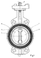
- the general structure of butterfly valve according to the invention incorporates the traditional parts of known butterfly valves, with a body 1 generally annular having a main bore for fluid passage 2.
- a butterfly 3 is mounted rotatable in the main bore 2 of the body 1.
- the butterfly 3 has the general shape of a disc, with a generally spherical edge 4.
- the butterfly 3 is rotated by a drive shaft 5 passing through a transverse bore 6 of the body 1, along the transverse axis II.
- Butterfly 3 is also held by a tree rear 7 housed in a rear bore 8 diametrically opposite to the transverse bore 6, in the body 1.
- the butterfly 3 is centered on the transverse axis II, that is to say that the transverse axis II of rotation passes by a diameter of the disc forming the butterfly 3.
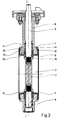
- the cuff 9 comprises a tubular central part 10, the outer face 11 of which is pressed against the bore wall 2 of the body 1 and is bordered by two annular radial lips 12 and 13 plating on the respective flanks 14 and 15 of the body 1.
- the central tubular part 10 is pierced with two transverse passages 16 and 17 crossed respectively by the drive shaft 5 and by the rear shaft 7.
- the inner surface 18 of the tubular central part 10 of the cuff is generally cylindrical of revolution, and comprises two zones 19 and 20 reinforced with sealing in the vicinity of one and the other of the transverse passages 16 and 17.
- the reinforced zones 20 are planar, and are angularly connected, for example as shown in reference 21, to the rest of the inner surface 18 of the central cuff part.
- the passages 16 and 17 are simple transverse bores with smooth walls, in which pass the drive shaft and the rear shaft.
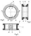
- Figures 6 to 8 show an embodiment of an improved cuff according to the present invention, to obtain a significantly improved seal.
- the reinforced sealing zones 19 and 20, distant from each other by a distance D1 less than the average diameter D of the inner surface 18 of the tubular central part 10, are connected to the cylindrical part of revolution 18 by cylindrical connection surfaces with regular concavity facing towards the inside the valve.
- connection surfaces 21 and 22 for the reinforced zone 19 and the connection surfaces 23 and 24 for the reinforced zone 20 are connected to the cylindrical part of revolution 18 by cylindrical connection surfaces with regular concavity facing towards the inside the valve.
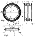
- FIGS 9 to 11 illustrate three different embodiments for these connection surfaces.
- connection surface 21 of the reinforced zone 19 is a cylindrical surface of revolution, of radius R1 substantially equal to half of the average radius R of the interior surface 18 of the tubular central cuff part, and this surface of connection 21 occupies an angle A equal to approximately 10 degrees from the inner surface circumference of the tubular central cuff part. This is the minimum connection surface, below which the sealing efficiency is not appreciably increased compared to known cuff structures.
- connection surface 21 occupies an angle A of approximately 88 degrees, with a radius slightly less than the average radius R of the inner surface of the central tubular cuff part.
- connection surface occupies an angle A equal to 90 degrees, and it is elliptical, centered at the center C of the main bore.
- the inner surface of the tubular central cuff part is entirely elliptical.
- a cylindrical connection surface 21 of revolution can thus occupy an angle A of between 10 and 90 degrees.
- the transverse passages 16 and 17 have the shape of a tubular sleeve, the inner surface of which includes annular decompression grooves such as groove 25.
- the presence of these grooves substantially improves the seal between the shafts d drive front 5 and rear 7 and cuff 9.
- On can advantageously provide three decompression grooves such as groove 25, as shown in FIG. 7.
- the cuff 9 shown in Figures 6 to 11 can advantageously be made of elastomer or plastomer.
- the body 1 can be rough foundry, because the significant increase in efficiency obtained by the cuff makes it possible to compensate for the dimensional variations resulting from the processes for manufacturing bodies by foundry.
Landscapes
- Engineering & Computer Science (AREA)
- General Engineering & Computer Science (AREA)
- Mechanical Engineering (AREA)
- Lift Valve (AREA)
Applications Claiming Priority (2)
| Application Number | Priority Date | Filing Date | Title |
|---|---|---|---|
| FR9206582 | 1992-05-26 | ||
| FR929206582A FR2691781B1 (fr) | 1992-05-26 | 1992-05-26 | Vanne papillon a manchette perfectionnee. |
Publications (2)
| Publication Number | Publication Date |
|---|---|
| EP0572333A1 true EP0572333A1 (de) | 1993-12-01 |
| EP0572333B1 EP0572333B1 (de) | 1996-01-10 |
Family
ID=9430293
Family Applications (1)
| Application Number | Title | Priority Date | Filing Date |
|---|---|---|---|
| EP93420205A Expired - Lifetime EP0572333B1 (de) | 1992-05-26 | 1993-05-21 | Klappenventil mit verbesserter Dichtmanschette |
Country Status (4)
| Country | Link |
|---|---|
| EP (1) | EP0572333B1 (de) |
| AT (1) | ATE132948T1 (de) |
| DE (1) | DE69301274T2 (de) |
| FR (1) | FR2691781B1 (de) |
Cited By (2)
| Publication number | Priority date | Publication date | Assignee | Title |
|---|---|---|---|---|
| WO2014102356A1 (en) * | 2012-12-28 | 2014-07-03 | Saint-Gobain Performance Plastics France | Seal for a valve and valve incorporating such a seal |
| EP3473900A4 (de) * | 2016-06-17 | 2020-02-12 | Asahi Yukizai Corporation | Drosselventilsitzring und drosselventil damit |
Families Citing this family (2)
| Publication number | Priority date | Publication date | Assignee | Title |
|---|---|---|---|---|
| RU2146783C1 (ru) * | 1998-04-02 | 2000-03-20 | Закрытое акционерное общество "Арматэк" | Поворотный дисковый затвор |
| RU194290U1 (ru) * | 2019-08-15 | 2019-12-05 | Акционерное общество "Машиностроительный завод "Армалит" | Затвор дисковый с тройным эксцентриситетом |
Citations (3)
| Publication number | Priority date | Publication date | Assignee | Title |
|---|---|---|---|---|
| US3784157A (en) * | 1972-05-15 | 1974-01-08 | Fmc Corp | Butterfly valve stem seal energizer |
| DE2503727A1 (de) * | 1975-01-30 | 1976-08-05 | Rheinisches Metallwerk Gmbh | Klappenventil |
| US4133513A (en) * | 1976-10-26 | 1979-01-09 | Celanese Corporation | Butterfly valve assembly |
-
1992
- 1992-05-26 FR FR929206582A patent/FR2691781B1/fr not_active Expired - Fee Related
-
1993
- 1993-05-21 AT AT93420205T patent/ATE132948T1/de not_active IP Right Cessation
- 1993-05-21 DE DE69301274T patent/DE69301274T2/de not_active Expired - Fee Related
- 1993-05-21 EP EP93420205A patent/EP0572333B1/de not_active Expired - Lifetime
Patent Citations (3)
| Publication number | Priority date | Publication date | Assignee | Title |
|---|---|---|---|---|
| US3784157A (en) * | 1972-05-15 | 1974-01-08 | Fmc Corp | Butterfly valve stem seal energizer |
| DE2503727A1 (de) * | 1975-01-30 | 1976-08-05 | Rheinisches Metallwerk Gmbh | Klappenventil |
| US4133513A (en) * | 1976-10-26 | 1979-01-09 | Celanese Corporation | Butterfly valve assembly |
Cited By (4)
| Publication number | Priority date | Publication date | Assignee | Title |
|---|---|---|---|---|
| WO2014102356A1 (en) * | 2012-12-28 | 2014-07-03 | Saint-Gobain Performance Plastics France | Seal for a valve and valve incorporating such a seal |
| CN105143737A (zh) * | 2012-12-28 | 2015-12-09 | 法国圣戈班性能塑料公司 | 用于阀门的密封件和结合有这种密封件的阀门 |
| EP3473900A4 (de) * | 2016-06-17 | 2020-02-12 | Asahi Yukizai Corporation | Drosselventilsitzring und drosselventil damit |
| US10781925B2 (en) | 2016-06-17 | 2020-09-22 | Asahi Yukizai Corporation | Butterfly valve seat ring and butterfly valve provided with same |
Also Published As
| Publication number | Publication date |
|---|---|
| FR2691781A1 (fr) | 1993-12-03 |
| EP0572333B1 (de) | 1996-01-10 |
| DE69301274D1 (de) | 1996-02-22 |
| FR2691781B1 (fr) | 1994-08-05 |
| DE69301274T2 (de) | 1996-08-01 |
| ATE132948T1 (de) | 1996-01-15 |
Similar Documents
| Publication | Publication Date | Title |
|---|---|---|
| EP0020239B1 (de) | Absperrklappe | |
| EP0096645B1 (de) | Dichtungsvorrichtung für ein Kugelkükenventil | |
| WO1994001703A1 (fr) | Robinet a tournant spherique ou cylindrique equipe d'un insert | |
| LU84106A1 (fr) | Vanne-papillon a corps revetu | |
| EP0019496B1 (de) | Drosselklappe und Verfahren zu ihrer Herstellung | |
| BE1001484A4 (fr) | Robinet etanche aux gaz, pouvant etre mis en position en rotation ou axialement. | |
| EP0572333B1 (de) | Klappenventil mit verbesserter Dichtmanschette | |
| FR2645206A1 (fr) | Soupape a air pour pompe a diaphragme | |
| FR2697888A1 (fr) | Vanne de régulation à bille ou à boisseau. | |
| FR2716517A1 (fr) | Vanne rotative. | |
| FR2730293A1 (fr) | Clapet antiretour charge par un ressort, comportant un organe d'obturation pousse par un element a ressort contre un siege de clapet dans un corps de clapet | |
| EP0027765A1 (de) | Kugelhahn und Verfahren zu dessen Herstellung | |
| FR2547012A2 (fr) | Robinet lubrifie a obturateur tournant fendu | |
| FR2553489A1 (fr) | Robinet d'arret pour liquides | |
| FR2575263A1 (fr) | Valve en champignon montee en ligne | |
| EP1358414B1 (de) | Klappegehäuse mit eingerasteter manchette | |
| FR2543237A1 (fr) | Joint homocinetique elastique | |
| FR2664351A3 (fr) | Vanne papillon. | |
| EP0202156A1 (de) | Ringförmige Dichtungsanordnung, insbesondere für Klappen oder Ventile | |
| FR2645235A1 (fr) | Ensemble d'etancheite, et actionneur rotatif commande par un fluide et le comportant | |
| EP0430748A1 (de) | In Axialsinn fixiertes Antriebsgelenk | |
| FR2664016A1 (fr) | Robinet a boisseau. | |
| FR2516627A1 (fr) | Robinet a cle, notamment robinet a boisseau | |
| FR2644111A1 (fr) | Joint tournant pour pneumatiques | |
| FR2784145A1 (fr) | Appareil de deplacement de fluide du type a spirale |
Legal Events
| Date | Code | Title | Description |
|---|---|---|---|
| PUAI | Public reference made under article 153(3) epc to a published international application that has entered the european phase |
Free format text: ORIGINAL CODE: 0009012 |
|
| AK | Designated contracting states |
Kind code of ref document: A1 Designated state(s): AT BE CH DE DK ES FR GB GR IT LI LU NL PT SE |
|
| 17P | Request for examination filed |
Effective date: 19931217 |
|
| 17Q | First examination report despatched |
Effective date: 19950616 |
|
| GRAA | (expected) grant |
Free format text: ORIGINAL CODE: 0009210 |
|
| AK | Designated contracting states |
Kind code of ref document: B1 Designated state(s): AT BE CH DE DK ES FR GB GR IT LI LU NL PT SE |
|
| PG25 | Lapsed in a contracting state [announced via postgrant information from national office to epo] |
Ref country code: NL Free format text: LAPSE BECAUSE OF FAILURE TO SUBMIT A TRANSLATION OF THE DESCRIPTION OR TO PAY THE FEE WITHIN THE PRESCRIBED TIME-LIMIT Effective date: 19960110 Ref country code: IT Free format text: LAPSE BECAUSE OF FAILURE TO SUBMIT A TRANSLATION OF THE DESCRIPTION OR TO PAY THE FEE WITHIN THE PRESCRIBED TIME-LIMIT;WARNING: LAPSES OF ITALIAN PATENTS WITH EFFECTIVE DATE BEFORE 2007 MAY HAVE OCCURRED AT ANY TIME BEFORE 2007. THE CORRECT EFFECTIVE DATE MAY BE DIFFERENT FROM THE ONE RECORDED. Effective date: 19960110 Ref country code: GR Free format text: LAPSE BECAUSE OF FAILURE TO SUBMIT A TRANSLATION OF THE DESCRIPTION OR TO PAY THE FEE WITHIN THE PRESCRIBED TIME-LIMIT Effective date: 19960110 Ref country code: ES Free format text: THE PATENT HAS BEEN ANNULLED BY A DECISION OF A NATIONAL AUTHORITY Effective date: 19960110 Ref country code: DK Effective date: 19960110 Ref country code: AT Effective date: 19960110 |
|
| REF | Corresponds to: |
Ref document number: 132948 Country of ref document: AT Date of ref document: 19960115 Kind code of ref document: T |
|
| REF | Corresponds to: |
Ref document number: 69301274 Country of ref document: DE Date of ref document: 19960222 |
|
| REG | Reference to a national code |
Ref country code: CH Ref legal event code: NV Representative=s name: ZIMMERLI, WAGNER & PARTNER AG |
|
| PG25 | Lapsed in a contracting state [announced via postgrant information from national office to epo] |
Ref country code: SE Effective date: 19960410 Ref country code: PT Effective date: 19960410 |
|
| GBT | Gb: translation of ep patent filed (gb section 77(6)(a)/1977) |
Effective date: 19960418 |
|
| NLV1 | Nl: lapsed or annulled due to failure to fulfill the requirements of art. 29p and 29m of the patents act | ||
| PLBE | No opposition filed within time limit |
Free format text: ORIGINAL CODE: 0009261 |
|
| STAA | Information on the status of an ep patent application or granted ep patent |
Free format text: STATUS: NO OPPOSITION FILED WITHIN TIME LIMIT |
|
| 26N | No opposition filed | ||
| PGFP | Annual fee paid to national office [announced via postgrant information from national office to epo] |
Ref country code: BE Payment date: 20010427 Year of fee payment: 9 |
|
| PGFP | Annual fee paid to national office [announced via postgrant information from national office to epo] |
Ref country code: LU Payment date: 20010507 Year of fee payment: 9 |
|
| PGFP | Annual fee paid to national office [announced via postgrant information from national office to epo] |
Ref country code: FR Payment date: 20010510 Year of fee payment: 9 |
|
| PGFP | Annual fee paid to national office [announced via postgrant information from national office to epo] |
Ref country code: GB Payment date: 20010516 Year of fee payment: 9 |
|
| PGFP | Annual fee paid to national office [announced via postgrant information from national office to epo] |
Ref country code: CH Payment date: 20010529 Year of fee payment: 9 |
|
| PGFP | Annual fee paid to national office [announced via postgrant information from national office to epo] |
Ref country code: DE Payment date: 20010622 Year of fee payment: 9 |
|
| REG | Reference to a national code |
Ref country code: GB Ref legal event code: IF02 |
|
| PG25 | Lapsed in a contracting state [announced via postgrant information from national office to epo] |
Ref country code: LU Free format text: LAPSE BECAUSE OF NON-PAYMENT OF DUE FEES Effective date: 20020521 Ref country code: GB Free format text: LAPSE BECAUSE OF NON-PAYMENT OF DUE FEES Effective date: 20020521 |
|
| PG25 | Lapsed in a contracting state [announced via postgrant information from national office to epo] |
Ref country code: LI Free format text: LAPSE BECAUSE OF NON-PAYMENT OF DUE FEES Effective date: 20020531 Ref country code: CH Free format text: LAPSE BECAUSE OF NON-PAYMENT OF DUE FEES Effective date: 20020531 Ref country code: BE Free format text: LAPSE BECAUSE OF NON-PAYMENT OF DUE FEES Effective date: 20020531 |
|
| PG25 | Lapsed in a contracting state [announced via postgrant information from national office to epo] |
Ref country code: DE Free format text: LAPSE BECAUSE OF NON-PAYMENT OF DUE FEES Effective date: 20021203 |
|
| GBPC | Gb: european patent ceased through non-payment of renewal fee |
Effective date: 20020521 |
|
| REG | Reference to a national code |
Ref country code: CH Ref legal event code: PL |
|
| PG25 | Lapsed in a contracting state [announced via postgrant information from national office to epo] |
Ref country code: FR Free format text: LAPSE BECAUSE OF NON-PAYMENT OF DUE FEES Effective date: 20030131 |
|
| REG | Reference to a national code |
Ref country code: FR Ref legal event code: ST |