EP0572323B1 - Length-measuring device for elongated moving objects - Google Patents
Length-measuring device for elongated moving objects Download PDFInfo
- Publication number
- EP0572323B1 EP0572323B1 EP19930401356 EP93401356A EP0572323B1 EP 0572323 B1 EP0572323 B1 EP 0572323B1 EP 19930401356 EP19930401356 EP 19930401356 EP 93401356 A EP93401356 A EP 93401356A EP 0572323 B1 EP0572323 B1 EP 0572323B1
- Authority
- EP
- European Patent Office
- Prior art keywords
- carriages
- speed
- marker
- measurement
- roundabout
- Prior art date
- Legal status (The legal status is an assumption and is not a legal conclusion. Google has not performed a legal analysis and makes no representation as to the accuracy of the status listed.)
- Expired - Lifetime
Links
- 238000005259 measurement Methods 0.000 claims description 32
- 230000033001 locomotion Effects 0.000 claims description 16
- 238000007667 floating Methods 0.000 claims description 9
- 238000006243 chemical reaction Methods 0.000 claims description 4
- 230000000694 effects Effects 0.000 claims description 2
- 239000003550 marker Substances 0.000 claims 9
- NJPPVKZQTLUDBO-UHFFFAOYSA-N novaluron Chemical compound C1=C(Cl)C(OC(F)(F)C(OC(F)(F)F)F)=CC=C1NC(=O)NC(=O)C1=C(F)C=CC=C1F NJPPVKZQTLUDBO-UHFFFAOYSA-N 0.000 claims 3
- 239000000047 product Substances 0.000 description 59
- 238000004519 manufacturing process Methods 0.000 description 4
- 239000011120 plywood Substances 0.000 description 3
- 238000011144 upstream manufacturing Methods 0.000 description 3
- 230000005540 biological transmission Effects 0.000 description 2
- 230000006835 compression Effects 0.000 description 2
- 238000007906 compression Methods 0.000 description 2
- 239000000463 material Substances 0.000 description 2
- 238000009825 accumulation Methods 0.000 description 1
- 238000005452 bending Methods 0.000 description 1
- 238000010276 construction Methods 0.000 description 1
- 238000010924 continuous production Methods 0.000 description 1
- 230000001186 cumulative effect Effects 0.000 description 1
- 238000001514 detection method Methods 0.000 description 1
- 238000006073 displacement reaction Methods 0.000 description 1
- 230000006870 function Effects 0.000 description 1
- 239000002184 metal Substances 0.000 description 1
- 238000005272 metallurgy Methods 0.000 description 1
- 238000000034 method Methods 0.000 description 1
- 239000003973 paint Substances 0.000 description 1
- 238000007747 plating Methods 0.000 description 1
- 230000003252 repetitive effect Effects 0.000 description 1
- 230000000284 resting effect Effects 0.000 description 1
- 238000005096 rolling process Methods 0.000 description 1
- 239000007787 solid Substances 0.000 description 1
- 125000006850 spacer group Chemical group 0.000 description 1
- 239000013589 supplement Substances 0.000 description 1
- 230000009897 systematic effect Effects 0.000 description 1
- 238000005491 wire drawing Methods 0.000 description 1
Images

Classifications
-
- G—PHYSICS
- G01—MEASURING; TESTING
- G01B—MEASURING LENGTH, THICKNESS OR SIMILAR LINEAR DIMENSIONS; MEASURING ANGLES; MEASURING AREAS; MEASURING IRREGULARITIES OF SURFACES OR CONTOURS
- G01B11/00—Measuring arrangements characterised by the use of optical techniques
- G01B11/02—Measuring arrangements characterised by the use of optical techniques for measuring length, width or thickness
- G01B11/04—Measuring arrangements characterised by the use of optical techniques for measuring length, width or thickness specially adapted for measuring length or width of objects while moving
- G01B11/043—Measuring arrangements characterised by the use of optical techniques for measuring length, width or thickness specially adapted for measuring length or width of objects while moving for measuring length
Definitions
- the present invention relates to a device for measuring the length of long products in movement. It is more particularly usable in the cable or pipe industry, but it can also be used in the field of floor coverings, for measuring the length of covering plies produced by machines. For example, it can be used to measure lengths of carpet. It can also be used in metallurgy, in wire drawing, and more generally for the measurement of any long object having at a stage of its manufacture a scroll in front of a measuring device.
- the most commonly used length meters include a set of wheels, or continuous strips, kept in contact with the product to be measured, as for example described in the document EP-A-0 457 739. Maintaining in contact is exercised by an elastic compression system. This allows the measurement of products of different sections and different thicknesses. The measurement is carried out by counting the rotations of the system driven by friction with the product to be measured. It can be seen that the precision of these devices is between 2 and 3%. However, this precision depends essentially on the coefficients of friction of the materials in contact (the wheels and bands of the system and the product to be measured), the mechanical efficiency of the system, the clamping forces that can be accepted by the product to be measured, and the deformation. materials in contact (system and product to be measured).
- the object of the invention is to remedy these drawbacks by limiting the most important causes of fidelity faults. These causes are essentially linked to the friction of the measurement system on the product. In the invention this friction is very light, light indexes carried by the moving product, exert a low contact force on this product. In the invention, the friction of these indexes is not used to advance the measuring device.
- a control measures the progress of the indexes and causes the advancement of the corresponding measurement device. Given the differences in speed between the advancement of the measurement indexes and the advancement of the moving product, the indexes are, in a variant, kept floating in the measurement device. This flutter makes it possible to recover differences in speed between the device and the product.
- the measuring device rather than counting the number of revolutions made by the measuring device, the elapsed times between the passage of an index in front of the terminals of a set of detection terminals are counted.
- the distance between the terminals being known, this duration makes it possible to determine the speed with which, on the one hand, the measuring device is controlled, and with which, on the other hand, a measurement is made of the length of the long product in movement.
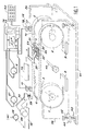
- FIG. 1 represents a device for measuring the length of long moving products according to the invention.
- This device comprises as a means of driving the milestones a carousel constituted, in the example shown, by at least two toothed pulleys, the pulleys 1 and 2, connected together by a toothed belt 3.
- the set of pulleys 1 and 2 was doubled by a second set of pulleys 4 and 5 mounted parallel to the pulleys 1 and 2 respectively and connected by a toothed belt 10.
- the carousel is motorized by a motor 6 which drives the pulley 1 and the pulley 4.
- the carousel shown here has the shape of a flat ellipse. It could have a different shape, for example triangular, if we had added a third pulley offset between the two pulleys 1 and 2.
- the carousel carries milestones 7, 8 and 9 fixed to the toothed belts 3 and 10.
- three milestones have been shown.
- the distance between the markers is preferably of the same order as a distance D between terminals 11 and 12 of a set of measurement terminals. But this is not necessary. It will be possible to show that the device of the invention could be operated with only two milestones, or even just one, but that in this case the risks of measurement error could arise. In these cases, however, in accordance with the invention, the precision fidelity faults due to the friction forces against the product to be measured would be reduced. We will explain later why a number of milestones equal to three is preferred. In practice, more milestones will be put into practice if the device is shorter, if the distance D is small.
- a stopwatch and a conversion device are used to convert a measurement of duration into a measurement of running length.
- the chronometer is represented by the clock 13 of a microprocessor 14.
- the microprocessor 14 also executes a conversion program stored in a memory 15.
- the product in travel 16 is a cable.
- the terminals 11 and 12 are quite simply each of the photoelectric cells comprising a light-emitting diode 17 emitting light in the direction of a photodetector 18.
- the milestone 7 has an index which temporarily masks, at the time of its passage, the transmission of this light. This break in transmission is detected by the photodetector 18, and is transformed into a signal which is received by the microprocessor 14. This deduces therefrom the passage times and therefore consequently the durations, the speeds, and the lengths of the products in movement. .
- the milestones are kept floating in the carousel.
- FIG 1 An example of this embodiment is shown in Figure 1 where a milestone 7 is constituted by a carriage 20 having a cavity. Crosswise to this cavity, a sliding axis 21 has been fixed. The sliding axis 21 is oriented, in the cavity of the carriage 20, parallel to the direction of movement of the stake 7 with the carousel. The carriage is moreover held at the notched belts 3 and 10 by lugs 22 and 23 riveted to these belts.
- a slider 24 is mounted to slide freely along the sliding axis 21. The slider 24 carries an index 25. This one is, here, a metallic piece in the shape of a capital L.
- One end of the foot of this L is fixed, for example by riveting on the slide 24.
- folds the index 25 rises above the plane formed by the belts 3 and 10. These folds by elastic effect, press the mast of the index 25 in an L shape under the moving product 16.
- the elastic force is low.
- the free elevation of the index is of the order of 0.5 cm and holding the index against the product causes this index to drop by about 0.2 cm.
- the index can also be replaced by a small plate supported by a spring which would be carried by the slide 24, so that this plate playing the role of index comes to be pressed below the product in movement 16.
- the sliding of the slider 1 on the axis 21 is free, and the low friction of the index finger 25 under the product 16 is sufficient to make the slider travel throughout the space of the cavity of the carriage 20.
- the slider at a length of about 2 cm and has a possible stroke of more or less 2 cm on either side of a medium position.
- the weight of the slide 24 is very low.
- the slide 24 is for example made of plastic.
- the slide can move freely in the carriage 20, the friction of the index finger 25 under or on the product 16 is not intended to drive the carriage 20.
- the speed difference integrated throughout the duration of the passage of the index between terminal 11 and terminal 12 is less than the travel tolerance (plus or minus 2 cm) authorized for the slide inside the trolley 20. If necessary, the trolley and the possible stroke of the slide will be enlarged so that it does not come into abutment due to speed differences.
- the principle of the measurement is as follows.
- the speed deduced from the times of passage of the indexes 25 in terminals 11 and 12 serves to control, with the help of the microprocessor 14, the motor 6.
- the speed measured is zero, an additional device can be used.
- This additional device comprises for example a tachometric generator 27 driven by a rolling pad 28 which rolls by friction on the product 16.
- FIG. 2 shows schematically certain features of the invention.
- the carousel is shown by the flat ellipse simulating for example the toothed belt 3.
- the three milestones 7, 8 and 9 are also shown.
- the index 25 of the milestone 7 is in contact, this time higher, with the product 16 in movement.
- the indexes of the milestones 8 and 9 occupy a central position inside the cavities of their respective carriages. These central positions are obtained by the presence of small springs such as 31 and 32, located on either side of the slide 24 around the sliding shaft 21. The forces exerted by these springs 31, 32 are very low taking into account the freedom of movement of the slide 24.
- the terminals 11 and 12 are also shown separated by the distance D.
- the product in movement is supported by a set of rollers such as 33 to 37 which prevent the product from bending 16 and therefore ensure good contact of the index finger 25 with the product without, in addition, requiring too great an effort to support the index finger 25.
- the entire device is held between two solid plates 38 and 39 (FIG. 1), for example in metal and connected together by spacers such as 40.
- the assembly formed by the device held by the plates constitutes the measuring block. It is movable in height relative to a base 41, for example by means of endless screws such as 42 resting on pads 43 integral with the base 41 and rotating in nuts 44 integral with plates 38 or 39.
- This system can of course be replaced by a lever system or, preferably, by a motorized system with an electric or hydraulic motor.
- the height can be adjusted visually, by controlling the compression of the index finger 25 against the product 16.
- the base 41 carries the set of rollers 33 to 37.
- the milestone 8 arrives in front of the terminal 11 after the milestone 7 has passed in front of the terminal 12. Consequently the milestone 7 is at a distance d from the terminal 12 at the time t2 when the milestone 8 arrives in front of the terminal 11.
- the instant t2 is also stored in a microprocessor registers. The duration which separates the instants t2 and t0 is called t B.
- the constraint that the enslavement be always set by excess can be replaced by a simpler arrangement: in this one the distance which separates on the carousel two indexes from each other and greater than the distance D (known and tared) which separates the two terminals 11 and 12. For example, it is 3 or 4 cm higher. It could also be shown that the servo can be set by default, or even without preference, or that, also, the distances between the milestones are less than the distance D. This would then lead to systems for resetting the counters different from the one that will be written now. Consequently, the description of resetting and counting of lengths cannot be considered as limited to a case where these constraints of servo-control by excess, or by default, and greater distances should be respected.
- the distance D + d traveled by the index 25 is therefore equal to V xt B.
- V is itself equal to D / t A.
- the total distance traveled by index 25 is equal to D xt B / t A.
- this last formula is exact, even if the instant t2 occurs before the instant t1.
- the idea of the invention is then in this case that the distances traveled by each of the indexes are counted, until a next index comes to take over. This is the reason why in theory, although it would be impractical, one could even imagine having only one index.
- the distance traveled by the index 7 thus evaluated is kept in memory in memory 15.
- the toothed wheels have 44 teeth and the toothed belts have 132 teeth, exactly three times more. This leads to placing three milestones. Taking into account the interest of measuring the length on a straight portion of the pseudo ellipse, and taking into account the ratio of the radius of the wheels to the length of the belts the number of three milestones is essential.
- a belt is preferably taken, the length of which is an integer multiple of the circumference of the wheels. The number of milestones is in correspondence. This brings another advantage.
- these fasteners are reinforced with plywoods. These plywoods replace a tooth in their place on the belt.
- the toothed wheels have a tooth removed at the place where these plywoods must engage. This further justifies the interest of having an integer multiple. Even if it is not essential and if you could imagine having a flat belt.
- instant t2 relating to the history of milestone 7 becomes an instant t0 relating to milestone 8.
- the program contained in memory 15 has an accumulation function which makes it possible to add up all the successive distances crossed by each of the milestones.
- the distance to be measured corresponds to an integer multiple, or approaching, of the distance D. Consequently, the instant of stopping the scrolling has no reason to fall at the time of a t0 or t1 or t2 type instant.
- the length of the product which has passed is then equal to the cumulative sum of the elementary lengths measured, increased by the product V x dt, V being the last measure of the speed of movement of the product.
- start-up occurs as follows.
- a keyboard 45 connected to the microprocessor 14, the start of scrolling of the product is controlled.
- a motor 46 coupled to the product 16 and symbolically represented sets in motion the start of this scrolling.
- the tachometric generator 27 measures the start-up, and the microprocessor 14 in application of the program 15 controls the speed of the motor 6 to the speed of the motor 46.
- the milestone 7, which has been placed upstream of the terminal 11 passes so in front of this terminal and we measure an instant t0.
- the scrolling continues until the milestone 7 passes in front of the terminal 12.
- two operations are carried out.
- First we have a first speed measurement V D / t A. So we already count the speeds and the distance traveled as before (this time adding the 2 cm).
- the speed control with the generator is switched to a speed control resulting from the proper measurement of the speed V.
- the control with the tachometer generator can be of analog type, the control with the speed V is a digital type servo.
- the launch of the measuring device can then be provided by any other device, possibly even manually.
- the principle of the invention therefore consists in the continuous laying of light marks (milestones) on the surface of the product to be measured and then in the measurement, on a preferably straight path, of the speed by the position of these marks between two fixed points separated by a known distance (where between three or more fixed points separated by known distances).
- the general formula based on the ratio of times t B / t A would also be valid if, instead of using milestones, the product to be measured was marked with paint lines, and if the passage of these marks before a first then a second terminal.
Landscapes
- Physics & Mathematics (AREA)
- General Physics & Mathematics (AREA)
- Length Measuring Devices With Unspecified Measuring Means (AREA)
Description
La présente invention a pour objet un dispositif de mesure de longueur de produits longs en défilement. Elle est plus particulièrement utilisable dans l'industrie des câbles ou des tuyaux, mais elle peut également être utilisée dans le domaine des revêtements de sol, pour la mesure de la longueur de nappes de revêtement fabriquées par des machines. Par exemple, elle peut ainsi servir à mesurer des longueurs de moquette. Elle peut être utilisée également dans la métallurgie, dans les tréfileries, et plus généralement pour la mesure d'un objet long quelconque présentant à un stade de sa fabrication un défilement devant un dispositif de mesure.The present invention relates to a device for measuring the length of long products in movement. It is more particularly usable in the cable or pipe industry, but it can also be used in the field of floor coverings, for measuring the length of covering plies produced by machines. For example, it can be used to measure lengths of carpet. It can also be used in metallurgy, in wire drawing, and more generally for the measurement of any long object having at a stage of its manufacture a scroll in front of a measuring device.
Les dispositifs connus de mesure de produits longs en défilement, qui comportent généralement des compteurs, n'offrent pas de précision meilleure que quelques pourcent ni, surtout, une fidélité suffisante pour une correction systématique de l'erreur. De ce fait, les producteurs, qui fabriquent des grandes longueurs sur des lignes de production continues, ne peuvent pas maîtriser les suppléments de longueur délivrés gratuitement à leurs clients. Un meilleur contrôle de la précision de longueur peut se traduire immédiatement par une augmentation directe de la productivité et du gain.Known devices for measuring long running products, which generally include counters, offer no better accuracy than a few percent or, above all, sufficient fidelity for systematic correction of the error. As a result, producers who manufacture long lengths on continuous production lines cannot control the length supplements delivered free of charge to their customers. Better control of length accuracy can immediately translate into direct increases in productivity and gain.
Notamment la précision du comptage métrique est recherchée depuis longtemps par les fabricants de câbles électriques. En effet, la réalisation d'un câble électrique nécessite de nombreuses opérations successives. Plus les opérations sont proches du stade final, plus les pertes par surlongueur sont onéreuses. Dans le domaine de la fabrication des tubes en matière plastique, les produits sont généralement distribués en couronne de longueur de 25, 50 et 100 mètres. Sur ces produits de faible valeur ajoutée, l'intérêt économique de la précision n'est pas négligeable. Pour ce même domaine, l'évolution des techniques de construction des maisons implique maintenant la réalisation préalable d'écheveaux de gaines électriques, à répartir dans les dalles et les murs des maisons au moment du coulage du béton. Chaque brin de l'écheveau doit être mesuré avec précision pour éviter de livrer, par précaution, des longueurs bien trop grandes par rapport à la commande effectuée par le client.In particular, metric metering accuracy has long been sought by manufacturers of electric cables. Indeed, the realization of an electric cable requires many successive operations. The closer the operations are to the stadium final, the more expensive the losses by extra length. In the field of manufacturing plastic tubes, the products are generally distributed in crowns of
Les compteurs de longueur les plus couramment utilisés comportent un ensemble de roues, ou de bandes continues, maintenues en contact avec le produit à mesurer, comme par exemple décrit dans le document EP-A-0 457 739. Le maintien au contact est exercé par un système élastique de compression. Ceci permet la mesure de produits de différentes sections et de différentes épaisseurs. La mesure se réalise en comptabilisant les rotations du système entraîné par friction avec le produit à mesurer. On constate que la précision de ces dispositifs est comprise entre 2 et 3 %. Cependant cette précision dépend essentiellement des coefficients de frottement des matériaux en contact (les roues et bandes du système et le produit à mesurer), du rendement mécanique du système, des forces de serrage pouvant être acceptées par le produit à mesurer, et de la déformation des matériaux en contact (système et produit à mesurer). Il apparaît alors que du fait de la diversité très grande des besoins, le réglage de ces différents paramètres n'est optimal que pour un des produits à mesurer, pas pour les autres. Il en résulte que les appareils actuellement commercialisés fournissent des précisions variables, et non répétitives, en fonction des produits, de leur dimension, et de leur résistance à l'écrasement. En pratique la précision est aléatoire et seule la précision moyenne du système est de l'ordre de 3 %. L'erreur pouvant aller de 1 % à 10 % dans les pires cas.The most commonly used length meters include a set of wheels, or continuous strips, kept in contact with the product to be measured, as for example described in the document EP-A-0 457 739. Maintaining in contact is exercised by an elastic compression system. This allows the measurement of products of different sections and different thicknesses. The measurement is carried out by counting the rotations of the system driven by friction with the product to be measured. It can be seen that the precision of these devices is between 2 and 3%. However, this precision depends essentially on the coefficients of friction of the materials in contact (the wheels and bands of the system and the product to be measured), the mechanical efficiency of the system, the clamping forces that can be accepted by the product to be measured, and the deformation. materials in contact (system and product to be measured). It then appears that due to the very great diversity of needs, the adjustment of these different parameters is only optimal for one of the products to be measured, not for the others. It follows that the Currently marketed devices provide variable, not repetitive, accuracy, depending on the product, its size, and its crush resistance. In practice, the accuracy is random and only the average accuracy of the system is around 3%. The error can range from 1% to 10% in the worst cases.
L'invention a pour but de remédier à ces inconvénients en limitant les causes les plus importantes des défauts de fidélité. Ces causes sont essentiellement liées au frottement du système de mesure sur le produit. Dans l'invention ce frottement est très léger, des index légers emmenés par le produit en défilement, exercent un effort faible de contact sur ce produit. Dans l'invention la friction de ces index ne sert pas à faire avancer le dispositif de mesure. Dans un perfectionnement, un asservissement mesure l'avancement des index et provoque l'avancement du dispositif de mesure en correspondance. Compte tenu des différences de vitesse entre l'avancement des index de mesure et l'avancement du produit en défilement, les index sont, dans une variante, maintenus flottant dans le dispositif de mesure. Ce flottement permet de récupérer des différences de vitesse entre le dispositif et le produit. Par suite, plutôt que de compter le nombre de tours effectué par le dispositif de mesure on compte des durées écoulées entre le passage d'un index devant des bornes d'un jeu de bornes de détection. La distance entre les bornes étant connue cette durée permet de déterminer la vitesse avec laquelle d'une part on asservit le dispositif de mesure, et avec laquelle d'autre part on établit une mesure de longueur du produit long en défilement.The object of the invention is to remedy these drawbacks by limiting the most important causes of fidelity faults. These causes are essentially linked to the friction of the measurement system on the product. In the invention this friction is very light, light indexes carried by the moving product, exert a low contact force on this product. In the invention, the friction of these indexes is not used to advance the measuring device. In an improvement, a control measures the progress of the indexes and causes the advancement of the corresponding measurement device. Given the differences in speed between the advancement of the measurement indexes and the advancement of the moving product, the indexes are, in a variant, kept floating in the measurement device. This flutter makes it possible to recover differences in speed between the device and the product. As a result, rather than counting the number of revolutions made by the measuring device, the elapsed times between the passage of an index in front of the terminals of a set of detection terminals are counted. The distance between the terminals being known, this duration makes it possible to determine the speed with which, on the one hand, the measuring device is controlled, and with which, on the other hand, a measurement is made of the length of the long product in movement.
L'invention a donc pour objet dispositif de mesure de longueur de produits longs en défilement caractérisé en ce qu'il comporte
- un moyen pour entraîner des jalons en regard du produit en défilement, à la vitesse de défilement du produit,
- un jeu de bornes,
- un chronomètre pour repérer des dates de passage de ces jalons devant ces bornes,
- et un dispositif de conversion pour convertir une mesure de la durée séparant ces passages de ces jalons devant ces bornes en une mesure de longueur du produit qui défile.
- a means for driving milestones facing the moving product, at the product running speed,
- a set of terminals,
- a chronometer to locate dates of passage of these milestones in front of these terminals,
- and a conversion device for converting a measurement of the duration separating these passages from these milestones in front of these terminals into a measurement of the length of the product passing by.
L'invention sera mieux comprise à la lecture de la description qui suit à l'examen des figures qui l'accompagnent. Celles ci ne sont données qu'à titre indicatif et nullement limitatif de l'invention. Les figures montrent :
- figure 1 : un dispositif de mesure de longueur de produits en défilement conforme à l'invention ;
- figure 2 : des détails de réalisation du dispositif et une représentation schématique de la position des index ;
- figure 3 : le principe de la mesure effectuée avec le dispositif de l'invention.
- Figure 1: a device for measuring the length of moving products according to the invention;
- Figure 2: details of embodiment of the device and a schematic representation of the position of the indexes;
- Figure 3: the principle of the measurement made with the device of the invention.
La figure 1 représente un dispositif de mesure de longueur de produits longs en défilement selon l'invention. Ce dispositif comporte comme moyen d'entraînement des jalons un carrousel constitué, dans l'exemple représenté, par au moins deux poulies crantées, les poulies 1 et 2, reliées entres elles par une courroie crantée 3. De préférence, pour des raisons de stabilité, on a doublé le jeu des poulies 1 et 2 par un deuxième jeu de poulies 4 et 5 montées parallèlement aux poulies 1 et 2 respectivement et reliées par une courroie crantées 10. Le carrousel est motorisé par un moteur 6 qui entraîne la poulie 1 et la poulie 4. Le carrousel représenté a ici la forme d'une ellipse plate. Il pourrait avoir une forme différente, par exemple triangulaire, si on avait rajouté une troisième poulie décalée entre les deux poulies 1 et 2.FIG. 1 represents a device for measuring the length of long moving products according to the invention. This device comprises as a means of driving the milestones a carousel constituted, in the example shown, by at least two toothed pulleys, the
Le carrousel porte des jalons 7, 8 et 9 fixés aux courroies crantées 3 et 10. Dans l'exemple préféré représenté on a montré trois jalons. Il peut bien entendu y en avoir plus, notamment pour des raisons de taille du dispositif. La distance entre les jalons est de préférence du même ordre qu'une distance D entre des bornes 11 et 12 d'un jeu de bornes de mesure. Mais ce n'est pas nécessaire On pourra montrer qu'on pourrait faire fonctionner le dispositif de l'invention avec seulement deux jalons, voire même un seul, mais que dans ce cas les risques d'erreur de mesure pourraient subvenir. Dans ces cas cependant on réduirait, conformément à l'invention, les défauts de fidélité de précision dues aux efforts de frottement contre le produit à mesurer. On expliquera par la suite pourquoi un nombre de jalons égal à trois est préféré. En pratique on mettra en pratique plus de jalons si le dispositif est moins long, si la distance D est petite.The carousel carries
Dans l'invention on utilise un chronomètre et un dispositif de conversion pour convertir une mesure de durée en une mesure de longueur qui défile. Dans la pratique le chronomètre est représenté par l'horloge 13 d'un microprocesseur 14. Le microprocesseur 14 exécute par ailleurs un programme de conversion stocké dans une mémoire 15. Chaque fois qu'un jalon, par exemple le jalon 7, passe devant la borne 11 puis la borne 12 le programme de la mémoire 15 prévoit de prendre en compte le temps d'horloge délivré par l'horloge 13. On dispose alors en pratique d'une mesure de la vitesse V de déplacement du jalon 7, égale à la vitesse V de déplacement du produit long 16 en défilement. Cette mesure de la vitesse est liée à la connaissance de l'espacement D résidant entre les bornes 11 et 12. Dans l'exemple représenté le produit en défilement 16 est un câble. Dans la pratique les bornes 11 et 12 sont tout simplement chacune des cellules photoélectriques comportant une diode électroluminescente 17 émettant une lumière en direction d'un photodétecteur 18. Le jalon 7 comporte un index qui vient masquer temporairement, au moment de son passage, la transmission de cette lumière. Cette rupture de transmission est détectée par le photodetecteur 18, et est transformée en un signal qui est reçu par le microprocesseur 14. Celui ci en déduit les instants de passage et donc en conséquence les durées, les vitesses, et les longueurs des produits en défilement.In the invention, a stopwatch and a conversion device are used to convert a measurement of duration into a measurement of running length. In practice, the chronometer is represented by the
Dans un perfectionnement de l'invention, les jalons sont maintenus flottants dans le carrousel. Un exemple de cette réalisation est montré sur la figure 1 où un jalon 7 est constitué par un chariot 20 comportant une cavité. Transversalement à cette cavité, on a fixé un axe de glissement 21. L'axe de glissement 21 est orienté, dans la cavité du chariot 20, parallèlement au sens de déplacement du jalon 7 avec le carrousel. Le chariot est par ailleurs maintenu aux courroies crantées 3 et 10 par des pattes 22 et 23 rivetées à ces courroies. Un coulisseau 24 est monté libre en coulissement le long de l'axe de coulissement 21. Le coulisseau 24 porte un index 25 . Celui-ci est, ici, une pièce métallique en forme de L majuscule. Une extrémité du pied de ce L est fixée, par exemple par rivetage sur le coulisseau 24. Par des pliures l'index 25 s'élève au-dessus du plan formé par les courroies 3 et 10. Ces pliures par effet élastique, viennent plaquer le mât de l'index 25 en forme de L sous le produit en défilement 16. L'effort élastique est faible. Par exemple l'élévation libre de l'index est de l'ordre de 0,5 centimètre et le maintien de l'index contre le produit fait descendre cet index d'environ 0,2 centimètre. L'index peut par ailleurs être remplacé par un petit plateau soutenu par un ressort qui serait porté par le coulisseau 24, de manière à ce que ce plateau jouant le rôle d'index vienne se plaquer en dessous du produit en défilement 16.In an improvement of the invention, the milestones are kept floating in the carousel. An example of this embodiment is shown in Figure 1 where a
Le coulissement du coulisseau 1 sur l'axe 21 est libre, et le faible frottement de l'index 25 sous le produit 16 est suffisant pour faire voyager le coulisseau dans tout l'espace de la cavité du chariot 20. Dans un exemple le coulisseau à une longueur d'environ 2 cm et a une course possible de plus ou moins 2 cm de part et d'autre d'une position moyenne. Le poids du coulisseau 24 est très faible. Le coulisseau 24 est par exemple en matière plastique.The sliding of the slider 1 on the
Etant donné que le coulisseau peut se mouvoir librement dans le chariot 20, le frottement de l'index 25 sous ou sur le produit 16 n'est pas destiné à entraîner le chariot 20. Pour entraîner ce chariot, on utilise au contraire des informations de vitesse résultant de la mesure du déplacement des index pour commander, avec le microprocesseur 14, le moteur 6 de façon à ce que le chariot 20 soit entraîné à une vitesse très proche de la vitesse V. En pratique on s'arrange pour que l'écart de vitesse, intégré pendant toute la durée de passage de l'index entre la borne 11 et la borne 12 soit inférieur à la tolérance de course (plus ou moins 2 cm) autorisée au coulisseau à l'intérieur du chariot 20. Au besoin on agrandira le chariot et la course possible du coulisseau pour que celui-ci ne vienne pas en butée du fait des écarts de vitesse.Since the slide can move freely in the
Le principe de la mesure est la suivante. Quand le produit défile, la vitesse déduite des temps de passage des index 25 dans les bornes 11 et 12 sert à asservir, avec l'aide du microprocesseur 14, le moteur 6. Au moment du départ, compte tenu de ce que la vitesse mesurée est nulle, on peut utiliser un dispositif supplémentaire. Ce dispositif supplémentaire comporte par exemple une génératrice tachymétrique 27 entraînée par un patin roulant 28 qui roule par friction sur le produit 16. Le plaquage du patin 28 contre le produit en défilement 16 est assuré par un ressort 29 qui agit sur un bras de levier 30. Une fois que le démarrage a été effectué, par exemple une fois qu'un quelconque des chariots est passé en regard d'une borne puis d'une autre borne, on peut en déduire une vitesse et basculer l'asservissement, de la mesure tachymétrique à la mesure délivrée par le système constitué par les bornes 11 et 12, l'horloge 13, le microprocesseur 14 et le programme 15. Cependant il serait tout à fait possible de maintenir l'utilisation de la génératrice tachymétrique si celle-ci pouvait être assurée d'avoir un contact suffisamment fiable avec le produit pour que le flottement de l'index reste dans la tolérance. Dans tout les cas, il resterait que le moteur 6 serait asservi en vitesse, que l'index 25 serait flottant dans le chariot 20, et que ce serait le passage de l'index 25 devant les bornes 11 et 12 qui servirait à mesurer la longueur de produit en défilement.The principle of the measurement is as follows. When the product scrolls, the speed deduced from the times of passage of the
La figure 2 montre d'une manière schématique certaines particularités de l'invention. Le carrousel est montré par l'éllipse plate simulant par exemple la courroie crantée 3. Les trois jalons 7, 8 et 9 sont également représentés. L'index 25 du jalon 7 est en contact, supérieur cette fois, avec le produit 16 en défilement. Les index des jalons 8 et 9 occupent une position centrale à l'intérieur des cavités de leurs chariots respectifs. Ces positions centrales sont obtenues par présence de petits ressorts tels que 31 et 32, situés de part et d'autre du coulisseau 24 autour de l'arbre de coulissement 21. Les efforts exercés par ces ressorts 31, 32 sont très faibles compte tenu de la liberté de mouvement du coulisseau 24. Pour le jalon 7 on constate que la vitesse du carrousel est V + ε, supérieure à la vitesse V du produit 16 et de l'index 25. En conséquence l'index 25 recule petit à petit l'intérieur de la cavité du chariot qui le porte au fur et à mesure que ce chariot avance vers la borne 12.Figure 2 shows schematically certain features of the invention. The carousel is shown by the flat ellipse simulating for example the
On a également représenté les bornes 11 et 12 séparées par la distance D. Dans la représentation de la figure 2, qui est une solution préférée le produit en défilement est soutenu par un jeu de galets tels que 33 à 37 qui empêchent le fléchissement du produit 16 et assurent donc un bon contact de l'index 25 avec le produit sans nécessiter par ailleurs un trop gros effort de l'appui l'index 25.The
Pour assurer la mise en contact de l'index 25 avec le produit 16, et pour tenir compte des variations d'épaisseur des produits à mesurer, tout le dispositif est maintenu entre deux plaques massives 38 et 39 (figure 1), par exemple en métal et reliées entres elles par des entretoises tels que 40. L'ensemble formé par le dispositif maintenu par les plaques constitue le bloc de mesure. Il est mobile en hauteur par rapport à un socle 41, par exemple au moyen de vis sans fin telles que 42 s'appuyant sur des patins 43 solidaires du socle 41 et tournant dans des écrous 44 solidaires des plaques 38 ou 39. Ce système peut bien entendu être remplacé par un système à levier ou bien, de préférence, par un système motorisé avec un moteur électrique ou hydraulique. Le réglage de la hauteur peut être fait à vue, en contrôlant la compression de l'index 25 contre le produit 16. De préférence, compte tenu de ce que le contact est assuré par le dessus (et non par le dessous comme montré sur la figure 1) le socle 41 porte le jeu des galets 33 à 37.To ensure that the
Le fonctionnement de l'invention va maintenant être expliqué en regard de la figure 3. On étudie deux jalons actifs, le jalon 7 et le jalon 8. Lorsque le jalon 7 passe devant la borne 11, on enregistre dans un registre du microprocesseur 14 un temps t₀. Cet enregistrement est possible parce que quand le jalon 7 passe devant la borne, celle ci envoie un signal au microprocesseur 14 qui, à ce moment prélève le temps t₀. Ce temps peut être matérialisé par l'état d'un compteur qui évolue au rythme de l'horloge. Puis le jalon 7 se déplace et vient passer devant la borne 12. A ce moment on enregistre dans un autre registre du microprocesseur 14 le temps t₁. La durée de t₀ à t₁ sera dite tA. Dans le cas ou l'asservissement de vitesse a été fait par excès, et où la vitesse du chariot V + ε est supérieure à la vitesse V du produit à mesurer (ce qui est un cas préféré), le jalon 8 arrive devant la borne 11 après que le jalon 7 soit passé devant la borne 12. En conséquence le jalon 7 se trouve à une distance d de la borne 12 au moment t₂ où le jalon 8 arrive devant la borne 11. L'instant t₂ est également stocké dans un des registres du microprocesseur. La durée qui sépare les instants t₂ et t₀ est appelée tB.The operation of the invention will now be explained with reference to FIG. 3. We study two active milestones,
La contrainte voulant que l'asservissement soit toujours réglé par excès peut être remplacée par une disposition plus simple : dans celle ci la distance qui sépare sur le carrousel deux index l'un de l'autre et supérieure à la distance D (connue et tarée) qui sépare les deux bornes 11 et 12. Par exemple elle lui est supérieure de 3 ou 4 cm. On pourrait montrer par ailleurs que l'asservissement peut être réglé par défaut, ou même encore sans préférence, ou que, également, les distances qui séparent les jalons sont inférieures à la distance D. Ceci conduirait alors à des systèmes de remise à zéro des compteurs différents de celui qui va être écrit maintenant. En conséquence la description de la remise à zéro et de la comptabilisation des longueurs ne peut être considérée comme limitée à un cas où ces contraintes d'asservissement par excès, ou par défaut, et distances supérieures devraient être respectées.The constraint that the enslavement be always set by excess can be replaced by a simpler arrangement: in this one the distance which separates on the carousel two indexes from each other and greater than the distance D (known and tared) which separates the two
On peut constater que la mesure de vitesse V du produit en défilement est apprécié très exactement entre l'instant t₀ et l'instant t₁. Cette vitesse est égale à D/tA. Compte tenu de la faible distance parcourue en plus, d, par l'index 7 avant que l'index 8 ne vienne repérer l'instant t₂, on fait l'hypothèse, dans l'invention, que la vitesse s'est maintenue strictement égale pendant cette durée supplémentaire. En tout état de cause, même si ce n'est pas le cas, compte tenu du rapport des distances d/D et des variations faibles des vitesses, on obtient des erreurs de l'ordre de 0,05 pour mille. Par ailleurs, le but de l'asservissement est de faire en sorte que d soit le plus près possible de zéro. En pratique on obtient statistiquement pour d un écart limité à 1 mm, soit 2/1000 de la distance D. On peut raisonnablement estimer que la variation de vitesse sur 1 mm est très faible. Dans le cas où on aurait un seul jalon la distance d peut être plus forte, ce qui augmenterait les erreurs dues à ce choix sans remettre en cours cependant le principe de l'invention. En effet, en régime établi on ne constate pas d'erreur mesurable avec un seul jalon.We can see that the speed measurement V of the moving product is assessed very exactly between time t₀ and time t₁. This speed is equal to D / t A. Taking into account the small distance traveled in addition, d, by the
La distance D + d parcourue par l'index 25 est donc égale a V x tB. Or V est elle-même égale à D/tA. Donc la distance totale parcourue par l'index 25 est égale à D x tB/tA. On remarque par ailleurs que cette dernière formule est exacte, même si l'instant t₂ se produit avant l'instant t₁. L'idée de l'invention est alors dans ce cas que l'on compte les distances parcourues par chacun des index, jusqu'à ce qu'un index suivant vienne prendre le relais. C'est la raison pour laquelle en théorie, bien que cela serait peu pratique, on pourrait même imaginer n'avoir qu'un seul index. La distance parcourue par l'index 7 ainsi évaluée est gardée en mémoire dans la mémoire 15.The distance D + d traveled by the
Dans un exemple de réalisation les roues crantées ont 44 dents et les courroies crantées ont 132 dents, exactement trois fois plus. Ceci conduit à placer trois jalons. Compte tenu de l'intérêt de mesurer la longueur sur une portion droite de la pseudo ellipse, et compte tenu du rapport du rayon des roues à la longueur des courroies le nombre de trois jalons s'impose. En pratique on prend de préférence une courroie dont la longueur est un multiple entier de la circonférence des roues. Le nombre des jalons est en correspondance. Ceci apporte un autre avantage. Pour fixer les chariots avec les pattes 22 et 23 sur les courroies, on renforce ces fixations avec des contreplaques. Ces contreplaques remplacent une dent à leur endroit sur la courroie. De préférence les roues crantées ont une dent enlevée à l'endroit ou ces contreplaques doivent s'engéner. Ceci justifie encore plus l'intérêt d'avoir un multiple entier. Même si par ailleurs ce n'est pas indispensable et si on pouvait imaginer d'avoir une courroie plate.In an exemplary embodiment the toothed wheels have 44 teeth and the toothed belts have 132 teeth, exactly three times more. This leads to placing three milestones. Taking into account the interest of measuring the length on a straight portion of the pseudo ellipse, and taking into account the ratio of the radius of the wheels to the length of the belts the number of three milestones is essential. In practice, a belt is preferably taken, the length of which is an integer multiple of the circumference of the wheels. The number of milestones is in correspondence. This brings another advantage. To fix the carriages with the
En pratique on choisit aussi des roues crantées de grand diamètre. Ceci s'explique pour la raison suivante. Si le diamètre de la roue est grand, compte tenu de la faible élévation de l'index 0,5 cm, la vitesse tangentielle de l'index, au point de contact avec le produit long en défilement, est très sensiblement égale à la vitesse tangentielle des roues, qui elle est strictement égale à la vitesse du carroussel. Ceici ne serait pas le cas si le diamètre des roues était faible. Et c'est la raison pour laquelle on s'efforcera aussi de prévoir une élévation de l'index la plus faible possible.In practice, large notched wheels are also chosen. This is explained for the following reason. If the diameter of the wheel is large, taking into account the low elevation of the index finger 0.5 cm, the tangential speed of the index finger, at the point of contact with the long moving product, is very substantially equal to the speed tangential of the wheels, which is strictly equal to the speed of the carousel. This would not be the case if the diameter of the wheels was small. And this is the reason why we will also try to provide for the lowest possible index rise.
Puis la gestion de ce qui arrive au jalon 8 est effectuée de la même façon : l'instant t₂, relatif à l'historique du jalon 7 devient un instant t₀ relatif au jalon 8. Par ailleurs, le programme contenu dans la mémoire 15 possède une fonction d'accumulation qui permet d'additionner toutes les distances successives franchies par chacun des jalons. Lorsqu'on arrête le défilement du produit, il n'y a aucune raison pour que la distance à mesurer corresponde à un multiple entier, ou approchant, de la distance D. En conséquence, l'instant d'arrêt du défilement n'a aucune raison de tomber au moment d'un instant de type t0 ou t₁ ou t₂. On repère alors par rapport au dernier instant t₂ mesuré une durée dt. La longueur du produit qui a défilé est alors égale à la somme cumulée des longueurs élémentaires mesurées, augmentée du produit V x dt, V étant la dernière mesure de la vitesse de défilement du produit.Then the management of what happens to
Lors du démarrage, pour simplifier l'opération, on recalera le dispositif de mesure de telle façon qu'un des index soit à une position prédéterminée en amont de la borne 11. Par exemple on peut s'arranger en débrayant le moteur 6 pour que le jalon 7 soit placé 2 cm en amont de la borne 11. Le démarrage se produit alors de la façon suivante. Au moyen d'un clavier 45 relié au microprocesseur 14, on commande le démarrage de défilement du produit. Par exemple un moteur 46 couplé au produit 16 et symboliquement représenté met en mouvement le début de ce défilement. Au démarrage, la génératrice tachymétrique 27 mesure la mise en route, et le microprocesseur 14 en application du programme 15 asservit la vitesse du moteur 6 à la vitesse du moteur 46. Le jalon 7, qui a été placé en amont de la borne 11 passe donc devant cette borne et on en mesure un instant t₀. Le défilement se poursuit jusqu'à ce que le jalon 7 passe devant la borne 12. A cet instant on se livre à deux opérations. Premièrement on dispose d'une première mesure de vitesse V = D/tA. Donc on comptabilise déjà les vitesses et la distance parcourue comme précédemment (en ajoutant cette fois les 2 cm). Par ailleurs, connaissant la vitesse on bascule l'asservissement de vitesse avec la génératrice sur un asservissement de vitesse résultant de la mesure propre de la vitesse V. L'asservissement avec la génératrice tachymétrique peut être de type analogique, l'asservissement avec la vitesse V est un asservissement de type numérique. On remarque que si les problèmes de démarrage ne sont pas importants, en particulier lorsque que de très grandes distances sont calculées, que seule la précision de la mesure des distances est importante, et qu'on peut faire abstraction des défauts de démarrage, le lancement de l'appareil de mesure peut alors être procuré par tout autre dispositif, éventuellement même manuellement.During startup, to simplify the operation, we readjust the measuring device so that one of the indexes is at a predetermined position upstream of the terminal 11. For example, it is possible to disengage the motor 6 so that the
Le principe de l'invention consiste donc dans la pose en continu de repères légers (les jalons) sur la surface du produit à mesurer puis dans la mesure, sur une trajectoire de préférence rectiligne, de la vitesse par la position de ces repères entre deux points fixes séparés par une distance connue (où entre trois ou plusieurs points fixes séparés par des distances connues). La formule générale basée sur le rapport des temps tB/tA serait par ailleurs aussi valable si, au lieu d'utiliser des jalons, on marquait par des traits de peinture le produit à mesurer par endroits, et si on repérait le passage de ces marques devant une première puis une deuxième borne. On pourrait s'arranger, avec une connaissance même approximative de la vitesse de défilement, pour mettre en oeuvre la formule indiquée ci-dessus. Dans ce cas, "l'asservissement" serait immédiat puisque les marques très légères seraient portées directement par le produit. Comme cet asservissement serait parfait, il n'y aurait bien entendu plus besoin de flottement. En effet cela ne serait pas utile puisque les index colorés ou peints seraient fixes par rapport au produit.The principle of the invention therefore consists in the continuous laying of light marks (milestones) on the surface of the product to be measured and then in the measurement, on a preferably straight path, of the speed by the position of these marks between two fixed points separated by a known distance (where between three or more fixed points separated by known distances). The general formula based on the ratio of times t B / t A would also be valid if, instead of using milestones, the product to be measured was marked with paint lines, and if the passage of these marks before a first then a second terminal. One could arrange, with even an approximate knowledge of the scrolling speed, to implement the formula indicated above. In this case, "enslavement" would be immediate since very light marks would be worn directly by the product. As this enslavement would be perfect, there would of course no longer be any need for floating. Indeed this would not be useful since the colored or painted indexes would be fixed relative to the product.
Claims (12)
- Length measuring device for elongated moving objects, characterised by the fact that it comprises- a means for driving marker carriages opposite the moving object at approximately the speed at which the latter moves,- a set of terminals,- a chronometer to note data relating to the movement of these marker carriages past these termimals,- and a converter device for converting a measurement of the time elapsing between the respective passages of these marker carriages in front of these terminals into a measurement of the length of the moving object.
- Device according to Claim 1, characterised in that- the driving means comprises a motorized roundabout,- the marker carriages are mounted in a floating position in the roundabout, and- the speed at the motor of the roundabout is governed by the speed at which the object moves past.
- Device according to Claim 2, characterised in that the floating markers each comprise a carriage affixed to the roundabout, this carriage being equipped with a slide which performs in the carriage a movement parallel to the direction in which the object moves past, while a pointer flexibly mounted on this slide elastically contacts the moving object, the time occupied by the movement of the printers past the terminals being measured.
- Device according to either of Claims 2, 3, characterised in that it comprises:
- means for elastically keeping the marker carriages in a floating position around an average position in relation to the roundabout. - Device according to any one of Claims 2 - 4, characterised in that the automatic control of the motor of the roundabout includes a device whereby this motor, on starting up, will be governed by a tachymetric generator in contact with and driven by the moving object, and a device by which this motor is then controlled in accordance with a measurement of the speed of passage of the floating marker carriages, this speed measurement being derived from the time measurement.
- Device according to any one of Claims 2 - 5, characterised in that it comprises- a securing block for the moving parts of the roundabout,- a pedestal on which to stand the device and secure the block, and- a positioning device for moving the block in the pedestal and moving this block closer to the object moving past.
- Device according to Claim 6, characterised in that the block comprises- two plates kept parallel to each other by struts,- at least two notched pulleys mounted to rotate freely between these plates,- at least one notched belt driven by a motor pulley and driving the marker carriages, a motor driving the motor pulley.
- Device according to Claim 6 or 7, characterised in that the pedestal comprises
- a train of rollers to support the moving object during its passage in front of the device. - Device according to any one of Claims 2 - 8, characterised in that the roundabout comprises at least three marker carriages.
- Device according to any one of Claims 1 - 9, characterised in that the chronometer comprises a clock of a microprocessor which also effects the measurement conversion.
- Device according to any one of Claims 2 - 10, characterised in that the distance between the marker carriages on the roundabont is approximately equal to and preferably well above the distance between the terminals.
- Device according to any one of Claims 7 - 11, characterised in that the length of the belt is a whole multiple of the circumferences of the driving wheel.
Applications Claiming Priority (2)
| Application Number | Priority Date | Filing Date | Title |
|---|---|---|---|
| FR9206521A FR2691800B1 (en) | 1992-05-27 | 1992-05-27 | DEVICE FOR MEASURING THE LENGTH OF LONG RUNNING PRODUCTS. |
| FR9206521 | 1992-05-27 |
Publications (2)
| Publication Number | Publication Date |
|---|---|
| EP0572323A1 EP0572323A1 (en) | 1993-12-01 |
| EP0572323B1 true EP0572323B1 (en) | 1995-08-09 |
Family
ID=9430254
Family Applications (1)
| Application Number | Title | Priority Date | Filing Date |
|---|---|---|---|
| EP19930401356 Expired - Lifetime EP0572323B1 (en) | 1992-05-27 | 1993-05-27 | Length-measuring device for elongated moving objects |
Country Status (3)
| Country | Link |
|---|---|
| EP (1) | EP0572323B1 (en) |
| DE (1) | DE69300352T2 (en) |
| FR (1) | FR2691800B1 (en) |
Families Citing this family (1)
| Publication number | Priority date | Publication date | Assignee | Title |
|---|---|---|---|---|
| CN103852253B (en) * | 2012-12-05 | 2016-12-28 | 上海西门子医疗器械有限公司 | The measuring method of Timing Belt slackness, system and armarium |
Family Cites Families (3)
| Publication number | Priority date | Publication date | Assignee | Title |
|---|---|---|---|---|
| HU180827B (en) * | 1979-08-10 | 1983-04-29 | Koezponti Banyaszati Fejleszte | Method for measuring the resistance to wear of endless driving devices during operation |
| FR2582388A1 (en) * | 1985-05-24 | 1986-11-28 | Tech Bois Ameublement Centre | AUTOMATIC DEVICE FOR NON-CONTACT MEASUREMENT OF DIMENSIONS OF A PARALLELEPIPEDIC PIECE |
| SE466276B (en) * | 1990-05-17 | 1992-01-20 | Ericsson Telefon Ab L M | LENGTH SEATING EQUIPMENT FOR SEATING LONG-TREATED MATERIAL, LIKE CABLES |
-
1992
- 1992-05-27 FR FR9206521A patent/FR2691800B1/en not_active Expired - Fee Related
-
1993
- 1993-05-27 EP EP19930401356 patent/EP0572323B1/en not_active Expired - Lifetime
- 1993-05-27 DE DE1993600352 patent/DE69300352T2/en not_active Expired - Fee Related
Also Published As
| Publication number | Publication date |
|---|---|
| FR2691800B1 (en) | 1996-05-03 |
| EP0572323A1 (en) | 1993-12-01 |
| DE69300352T2 (en) | 1996-03-07 |
| FR2691800A1 (en) | 1993-12-03 |
| DE69300352D1 (en) | 1995-09-14 |
Similar Documents
| Publication | Publication Date | Title |
|---|---|---|
| EP0011595B1 (en) | Method and device for controlling the advance of a tape bearing marks at regular distances | |
| CH679347A5 (en) | ||
| CH678985A5 (en) | ||
| EP0180489B1 (en) | Apparatus for recording and reading information on a magnetic tape | |
| EP0572323B1 (en) | Length-measuring device for elongated moving objects | |
| EP3185090B1 (en) | Device for counting and displaying a fraction of a time unit | |
| EP0336858A1 (en) | Coilingbrake for tape-measure | |
| FR2510535A1 (en) | ASSEMBLY TAPE DISPENSER-APPLICATOR | |
| EP1510316B1 (en) | Method for production of sheets made from hydraulic binder, production line for said sheets and device for generation of an impression | |
| CH679086A5 (en) | ||
| FR2557068A1 (en) | DEVICE FOR MOUNTING ELECTRICAL COMPONENTS ONE BY ONE IN THE FORM OF A BELT | |
| CH704915A2 (en) | Jumping display device for moving disk of timepiece in instantaneous manner according to determined jumps, has reverser system arranged to transmit rotational movement to drive wheel during jump of lever | |
| FR2577476A1 (en) | ROTARY DRAWING BOARD WITH AUTOMATIC POSITIONING | |
| WO1989002570A1 (en) | Length measuring device with perforated tape | |
| FR2643346A1 (en) | Transfer device with pushing strips | |
| FR2707107A1 (en) | Lens shape measuring instrument. | |
| CH696561A5 (en) | Device for the power reserve display a watch movement and watch provided with such a display device. | |
| EP2414266B1 (en) | Device for detecting torque, printer and operating method | |
| FR2688770A1 (en) | Device for advancing a flexible strip or the like | |
| CH332874A (en) | Drive mechanism of the sound holder for sound recording and reproducing apparatus | |
| CH634407A5 (en) | DIMENSION MEASURING INSTRUMENT. | |
| FR2604382A1 (en) | Beam/carriage assembly comprising drive means | |
| FR2571024A1 (en) | Bottle labelling machine | |
| BE549960A (en) | ||
| FR2523922A1 (en) | Rotary head taking label from magazine and sticking on can - uses inversely rotating cam to drive sucker slide during pause in head rotation. |
Legal Events
| Date | Code | Title | Description |
|---|---|---|---|
| PUAI | Public reference made under article 153(3) epc to a published international application that has entered the european phase |
Free format text: ORIGINAL CODE: 0009012 |
|
| AK | Designated contracting states |
Kind code of ref document: A1 Designated state(s): CH DE GB LI |
|
| 17P | Request for examination filed |
Effective date: 19940526 |
|
| 17Q | First examination report despatched |
Effective date: 19940822 |
|
| GRAA | (expected) grant |
Free format text: ORIGINAL CODE: 0009210 |
|
| AK | Designated contracting states |
Kind code of ref document: B1 Designated state(s): CH DE GB LI |
|
| REF | Corresponds to: |
Ref document number: 69300352 Country of ref document: DE Date of ref document: 19950914 |
|
| GBT | Gb: translation of ep patent filed (gb section 77(6)(a)/1977) |
Effective date: 19950822 |
|
| PLBE | No opposition filed within time limit |
Free format text: ORIGINAL CODE: 0009261 |
|
| STAA | Information on the status of an ep patent application or granted ep patent |
Free format text: STATUS: NO OPPOSITION FILED WITHIN TIME LIMIT |
|
| 26N | No opposition filed | ||
| PGFP | Annual fee paid to national office [announced via postgrant information from national office to epo] |
Ref country code: CH Payment date: 19970425 Year of fee payment: 5 |
|
| PGFP | Annual fee paid to national office [announced via postgrant information from national office to epo] |
Ref country code: DE Payment date: 19970428 Year of fee payment: 5 |
|
| PGFP | Annual fee paid to national office [announced via postgrant information from national office to epo] |
Ref country code: GB Payment date: 19980416 Year of fee payment: 6 |
|
| PG25 | Lapsed in a contracting state [announced via postgrant information from national office to epo] |
Ref country code: GB Free format text: LAPSE BECAUSE OF NON-PAYMENT OF DUE FEES Effective date: 19980527 |
|
| PG25 | Lapsed in a contracting state [announced via postgrant information from national office to epo] |
Ref country code: LI Free format text: LAPSE BECAUSE OF NON-PAYMENT OF DUE FEES Effective date: 19980531 Ref country code: CH Free format text: LAPSE BECAUSE OF NON-PAYMENT OF DUE FEES Effective date: 19980531 |
|
| REG | Reference to a national code |
Ref country code: CH Ref legal event code: PL |
|
| GBPC | Gb: european patent ceased through non-payment of renewal fee |
Effective date: 19980527 |
|
| PG25 | Lapsed in a contracting state [announced via postgrant information from national office to epo] |
Ref country code: DE Free format text: LAPSE BECAUSE OF NON-PAYMENT OF DUE FEES Effective date: 19990302 |