EP0572323B1 - Längenmesseinrichtung für langgestreckte sich bewegende Objekte - Google Patents
Längenmesseinrichtung für langgestreckte sich bewegende Objekte Download PDFInfo
- Publication number
- EP0572323B1 EP0572323B1 EP19930401356 EP93401356A EP0572323B1 EP 0572323 B1 EP0572323 B1 EP 0572323B1 EP 19930401356 EP19930401356 EP 19930401356 EP 93401356 A EP93401356 A EP 93401356A EP 0572323 B1 EP0572323 B1 EP 0572323B1
- Authority
- EP
- European Patent Office
- Prior art keywords
- carriages
- speed
- marker
- measurement
- roundabout
- Prior art date
- Legal status (The legal status is an assumption and is not a legal conclusion. Google has not performed a legal analysis and makes no representation as to the accuracy of the status listed.)
- Expired - Lifetime
Links
- 238000005259 measurement Methods 0.000 claims description 32
- 230000033001 locomotion Effects 0.000 claims description 16
- 238000007667 floating Methods 0.000 claims description 9
- 238000006243 chemical reaction Methods 0.000 claims description 4
- 230000000694 effects Effects 0.000 claims description 2
- 239000003550 marker Substances 0.000 claims 9
- NJPPVKZQTLUDBO-UHFFFAOYSA-N novaluron Chemical compound C1=C(Cl)C(OC(F)(F)C(OC(F)(F)F)F)=CC=C1NC(=O)NC(=O)C1=C(F)C=CC=C1F NJPPVKZQTLUDBO-UHFFFAOYSA-N 0.000 claims 3
- 239000000047 product Substances 0.000 description 59
- 238000004519 manufacturing process Methods 0.000 description 4
- 239000011120 plywood Substances 0.000 description 3
- 238000011144 upstream manufacturing Methods 0.000 description 3
- 230000005540 biological transmission Effects 0.000 description 2
- 230000006835 compression Effects 0.000 description 2
- 238000007906 compression Methods 0.000 description 2
- 239000000463 material Substances 0.000 description 2
- 238000009825 accumulation Methods 0.000 description 1
- 238000005452 bending Methods 0.000 description 1
- 238000010276 construction Methods 0.000 description 1
- 238000010924 continuous production Methods 0.000 description 1
- 230000001186 cumulative effect Effects 0.000 description 1
- 238000001514 detection method Methods 0.000 description 1
- 238000006073 displacement reaction Methods 0.000 description 1
- 230000006870 function Effects 0.000 description 1
- 239000002184 metal Substances 0.000 description 1
- 238000005272 metallurgy Methods 0.000 description 1
- 238000000034 method Methods 0.000 description 1
- 239000003973 paint Substances 0.000 description 1
- 238000007747 plating Methods 0.000 description 1
- 230000003252 repetitive effect Effects 0.000 description 1
- 230000000284 resting effect Effects 0.000 description 1
- 238000005096 rolling process Methods 0.000 description 1
- 239000007787 solid Substances 0.000 description 1
- 125000006850 spacer group Chemical group 0.000 description 1
- 239000013589 supplement Substances 0.000 description 1
- 230000009897 systematic effect Effects 0.000 description 1
- 238000005491 wire drawing Methods 0.000 description 1
Images

Classifications
-
- G—PHYSICS
- G01—MEASURING; TESTING
- G01B—MEASURING LENGTH, THICKNESS OR SIMILAR LINEAR DIMENSIONS; MEASURING ANGLES; MEASURING AREAS; MEASURING IRREGULARITIES OF SURFACES OR CONTOURS
- G01B11/00—Measuring arrangements characterised by the use of optical techniques
- G01B11/02—Measuring arrangements characterised by the use of optical techniques for measuring length, width or thickness
- G01B11/04—Measuring arrangements characterised by the use of optical techniques for measuring length, width or thickness specially adapted for measuring length or width of objects while moving
- G01B11/043—Measuring arrangements characterised by the use of optical techniques for measuring length, width or thickness specially adapted for measuring length or width of objects while moving for measuring length
Definitions
- the present invention relates to a device for measuring the length of long products in movement. It is more particularly usable in the cable or pipe industry, but it can also be used in the field of floor coverings, for measuring the length of covering plies produced by machines. For example, it can be used to measure lengths of carpet. It can also be used in metallurgy, in wire drawing, and more generally for the measurement of any long object having at a stage of its manufacture a scroll in front of a measuring device.
- the most commonly used length meters include a set of wheels, or continuous strips, kept in contact with the product to be measured, as for example described in the document EP-A-0 457 739. Maintaining in contact is exercised by an elastic compression system. This allows the measurement of products of different sections and different thicknesses. The measurement is carried out by counting the rotations of the system driven by friction with the product to be measured. It can be seen that the precision of these devices is between 2 and 3%. However, this precision depends essentially on the coefficients of friction of the materials in contact (the wheels and bands of the system and the product to be measured), the mechanical efficiency of the system, the clamping forces that can be accepted by the product to be measured, and the deformation. materials in contact (system and product to be measured).
- the object of the invention is to remedy these drawbacks by limiting the most important causes of fidelity faults. These causes are essentially linked to the friction of the measurement system on the product. In the invention this friction is very light, light indexes carried by the moving product, exert a low contact force on this product. In the invention, the friction of these indexes is not used to advance the measuring device.
- a control measures the progress of the indexes and causes the advancement of the corresponding measurement device. Given the differences in speed between the advancement of the measurement indexes and the advancement of the moving product, the indexes are, in a variant, kept floating in the measurement device. This flutter makes it possible to recover differences in speed between the device and the product.
- the measuring device rather than counting the number of revolutions made by the measuring device, the elapsed times between the passage of an index in front of the terminals of a set of detection terminals are counted.
- the distance between the terminals being known, this duration makes it possible to determine the speed with which, on the one hand, the measuring device is controlled, and with which, on the other hand, a measurement is made of the length of the long product in movement.
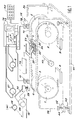
- FIG. 1 represents a device for measuring the length of long moving products according to the invention.
- This device comprises as a means of driving the milestones a carousel constituted, in the example shown, by at least two toothed pulleys, the pulleys 1 and 2, connected together by a toothed belt 3.
- the set of pulleys 1 and 2 was doubled by a second set of pulleys 4 and 5 mounted parallel to the pulleys 1 and 2 respectively and connected by a toothed belt 10.
- the carousel is motorized by a motor 6 which drives the pulley 1 and the pulley 4.
- the carousel shown here has the shape of a flat ellipse. It could have a different shape, for example triangular, if we had added a third pulley offset between the two pulleys 1 and 2.
- the carousel carries milestones 7, 8 and 9 fixed to the toothed belts 3 and 10.
- three milestones have been shown.
- the distance between the markers is preferably of the same order as a distance D between terminals 11 and 12 of a set of measurement terminals. But this is not necessary. It will be possible to show that the device of the invention could be operated with only two milestones, or even just one, but that in this case the risks of measurement error could arise. In these cases, however, in accordance with the invention, the precision fidelity faults due to the friction forces against the product to be measured would be reduced. We will explain later why a number of milestones equal to three is preferred. In practice, more milestones will be put into practice if the device is shorter, if the distance D is small.
- a stopwatch and a conversion device are used to convert a measurement of duration into a measurement of running length.
- the chronometer is represented by the clock 13 of a microprocessor 14.
- the microprocessor 14 also executes a conversion program stored in a memory 15.
- the product in travel 16 is a cable.
- the terminals 11 and 12 are quite simply each of the photoelectric cells comprising a light-emitting diode 17 emitting light in the direction of a photodetector 18.
- the milestone 7 has an index which temporarily masks, at the time of its passage, the transmission of this light. This break in transmission is detected by the photodetector 18, and is transformed into a signal which is received by the microprocessor 14. This deduces therefrom the passage times and therefore consequently the durations, the speeds, and the lengths of the products in movement. .
- the milestones are kept floating in the carousel.
- FIG 1 An example of this embodiment is shown in Figure 1 where a milestone 7 is constituted by a carriage 20 having a cavity. Crosswise to this cavity, a sliding axis 21 has been fixed. The sliding axis 21 is oriented, in the cavity of the carriage 20, parallel to the direction of movement of the stake 7 with the carousel. The carriage is moreover held at the notched belts 3 and 10 by lugs 22 and 23 riveted to these belts.
- a slider 24 is mounted to slide freely along the sliding axis 21. The slider 24 carries an index 25. This one is, here, a metallic piece in the shape of a capital L.
- One end of the foot of this L is fixed, for example by riveting on the slide 24.
- folds the index 25 rises above the plane formed by the belts 3 and 10. These folds by elastic effect, press the mast of the index 25 in an L shape under the moving product 16.
- the elastic force is low.
- the free elevation of the index is of the order of 0.5 cm and holding the index against the product causes this index to drop by about 0.2 cm.
- the index can also be replaced by a small plate supported by a spring which would be carried by the slide 24, so that this plate playing the role of index comes to be pressed below the product in movement 16.
- the sliding of the slider 1 on the axis 21 is free, and the low friction of the index finger 25 under the product 16 is sufficient to make the slider travel throughout the space of the cavity of the carriage 20.
- the slider at a length of about 2 cm and has a possible stroke of more or less 2 cm on either side of a medium position.
- the weight of the slide 24 is very low.
- the slide 24 is for example made of plastic.
- the slide can move freely in the carriage 20, the friction of the index finger 25 under or on the product 16 is not intended to drive the carriage 20.
- the speed difference integrated throughout the duration of the passage of the index between terminal 11 and terminal 12 is less than the travel tolerance (plus or minus 2 cm) authorized for the slide inside the trolley 20. If necessary, the trolley and the possible stroke of the slide will be enlarged so that it does not come into abutment due to speed differences.
- the principle of the measurement is as follows.
- the speed deduced from the times of passage of the indexes 25 in terminals 11 and 12 serves to control, with the help of the microprocessor 14, the motor 6.
- the speed measured is zero, an additional device can be used.
- This additional device comprises for example a tachometric generator 27 driven by a rolling pad 28 which rolls by friction on the product 16.
- FIG. 2 shows schematically certain features of the invention.
- the carousel is shown by the flat ellipse simulating for example the toothed belt 3.
- the three milestones 7, 8 and 9 are also shown.
- the index 25 of the milestone 7 is in contact, this time higher, with the product 16 in movement.
- the indexes of the milestones 8 and 9 occupy a central position inside the cavities of their respective carriages. These central positions are obtained by the presence of small springs such as 31 and 32, located on either side of the slide 24 around the sliding shaft 21. The forces exerted by these springs 31, 32 are very low taking into account the freedom of movement of the slide 24.
- the terminals 11 and 12 are also shown separated by the distance D.
- the product in movement is supported by a set of rollers such as 33 to 37 which prevent the product from bending 16 and therefore ensure good contact of the index finger 25 with the product without, in addition, requiring too great an effort to support the index finger 25.
- the entire device is held between two solid plates 38 and 39 (FIG. 1), for example in metal and connected together by spacers such as 40.
- the assembly formed by the device held by the plates constitutes the measuring block. It is movable in height relative to a base 41, for example by means of endless screws such as 42 resting on pads 43 integral with the base 41 and rotating in nuts 44 integral with plates 38 or 39.
- This system can of course be replaced by a lever system or, preferably, by a motorized system with an electric or hydraulic motor.
- the height can be adjusted visually, by controlling the compression of the index finger 25 against the product 16.
- the base 41 carries the set of rollers 33 to 37.
- the milestone 8 arrives in front of the terminal 11 after the milestone 7 has passed in front of the terminal 12. Consequently the milestone 7 is at a distance d from the terminal 12 at the time t2 when the milestone 8 arrives in front of the terminal 11.
- the instant t2 is also stored in a microprocessor registers. The duration which separates the instants t2 and t0 is called t B.
- the constraint that the enslavement be always set by excess can be replaced by a simpler arrangement: in this one the distance which separates on the carousel two indexes from each other and greater than the distance D (known and tared) which separates the two terminals 11 and 12. For example, it is 3 or 4 cm higher. It could also be shown that the servo can be set by default, or even without preference, or that, also, the distances between the milestones are less than the distance D. This would then lead to systems for resetting the counters different from the one that will be written now. Consequently, the description of resetting and counting of lengths cannot be considered as limited to a case where these constraints of servo-control by excess, or by default, and greater distances should be respected.
- the distance D + d traveled by the index 25 is therefore equal to V xt B.
- V is itself equal to D / t A.
- the total distance traveled by index 25 is equal to D xt B / t A.
- this last formula is exact, even if the instant t2 occurs before the instant t1.
- the idea of the invention is then in this case that the distances traveled by each of the indexes are counted, until a next index comes to take over. This is the reason why in theory, although it would be impractical, one could even imagine having only one index.
- the distance traveled by the index 7 thus evaluated is kept in memory in memory 15.
- the toothed wheels have 44 teeth and the toothed belts have 132 teeth, exactly three times more. This leads to placing three milestones. Taking into account the interest of measuring the length on a straight portion of the pseudo ellipse, and taking into account the ratio of the radius of the wheels to the length of the belts the number of three milestones is essential.
- a belt is preferably taken, the length of which is an integer multiple of the circumference of the wheels. The number of milestones is in correspondence. This brings another advantage.
- these fasteners are reinforced with plywoods. These plywoods replace a tooth in their place on the belt.
- the toothed wheels have a tooth removed at the place where these plywoods must engage. This further justifies the interest of having an integer multiple. Even if it is not essential and if you could imagine having a flat belt.
- instant t2 relating to the history of milestone 7 becomes an instant t0 relating to milestone 8.
- the program contained in memory 15 has an accumulation function which makes it possible to add up all the successive distances crossed by each of the milestones.
- the distance to be measured corresponds to an integer multiple, or approaching, of the distance D. Consequently, the instant of stopping the scrolling has no reason to fall at the time of a t0 or t1 or t2 type instant.
- the length of the product which has passed is then equal to the cumulative sum of the elementary lengths measured, increased by the product V x dt, V being the last measure of the speed of movement of the product.
- start-up occurs as follows.
- a keyboard 45 connected to the microprocessor 14, the start of scrolling of the product is controlled.
- a motor 46 coupled to the product 16 and symbolically represented sets in motion the start of this scrolling.
- the tachometric generator 27 measures the start-up, and the microprocessor 14 in application of the program 15 controls the speed of the motor 6 to the speed of the motor 46.
- the milestone 7, which has been placed upstream of the terminal 11 passes so in front of this terminal and we measure an instant t0.
- the scrolling continues until the milestone 7 passes in front of the terminal 12.
- two operations are carried out.
- First we have a first speed measurement V D / t A. So we already count the speeds and the distance traveled as before (this time adding the 2 cm).
- the speed control with the generator is switched to a speed control resulting from the proper measurement of the speed V.
- the control with the tachometer generator can be of analog type, the control with the speed V is a digital type servo.
- the launch of the measuring device can then be provided by any other device, possibly even manually.
- the principle of the invention therefore consists in the continuous laying of light marks (milestones) on the surface of the product to be measured and then in the measurement, on a preferably straight path, of the speed by the position of these marks between two fixed points separated by a known distance (where between three or more fixed points separated by known distances).
- the general formula based on the ratio of times t B / t A would also be valid if, instead of using milestones, the product to be measured was marked with paint lines, and if the passage of these marks before a first then a second terminal.
Landscapes
- Physics & Mathematics (AREA)
- General Physics & Mathematics (AREA)
- Length Measuring Devices With Unspecified Measuring Means (AREA)
Claims (12)
- Längenmeßeinrichtung für langgestreckte sich bewegende Objekte, dadurch gekennzeichnet, daß es aufweist:- eine Anordnung zum Antrieb von gegenüber dem Objekt angeordneten Markierungen mit im wesentlichen der Geschwindigkeit des Objekts,- ein Paar Anschlüsse,- einen Zeitmesser zur Erfassung der Vorbeilaufzeiten der Markierungen vor den Anschlüssen und- eine Wandleranordnung zur Umwandlung der Messung der Zeitdauer zwischen den Vorbeiläufen der Markierungen an den Anschlüssen in eine Messung der Länge des sich bewegenden Objektes.
- Einrichtung nach Anspruch 1, dadurch gekennzeichnet, daß- die Antriebsanordnung eine motorisierte Förderanordnung aufweist,- die Markierungen schwebend in der Förderanordnung gehalten sind und daß- der Motor der Förderanordnung mit seiner Geschwindigkeit mit der Bewegungsgeschwindigkeit des Objektes gekoppelt ist.
- Einrichtung nach Anspruch 2, dadurch gekennzeichnet, daß die schwebenden Markierungen jeweils einen an der Förderanordnung befestigten Träger aufweisen, wobei dieser Träger mit einem Gleitstück versehen ist, welches im Träger in einer Richtung parallel zur Bewegungsrichtung des Objektes gleitet und, elastisch im Gleitstück, eine Anzeigeanordnung. die elastisch bei Berührung mit dem sich bewegenden Objekt reagiert, wobei die Vorbeilaufzeiten der Anzeigeanordnung vor den Anschlüssen gemessen werden.
- Einrichtung nach einem der Ansprüche 2 oder 3, dadurch gekennzeichnet, daß sie aufweist:
- eine Anordnung zur elastischen Lagerung der schwebenden Markierungen um eine Mittelstellung bezüglich der Förderanordnung. - Einrichtung nach einem der Ansprüche 2 bis 4, dadurch gekennzeichnet, daß die Steuerung des Motors der Förderanordnung eine Anordnung aufweist, die beim Start den Motor mittels einer tachymetrischen Erzeugenden durch Berührung und Antrieb durch das sich bewegende Objekt steuert, sowie eine Anordnung aufweist, um anschließend den Motor als Funktion einer Messung der Vorbeilaufgeschwindigkeit der schwebenden Markierungen zu steuern, die von der Zeitdauermessung abgeleitet ist.
- Einrichtung nach einem der Ansprüche 2 bis 5, dadurch gekennzeichnet, daß sie aufweist- einen Halteblock für die Bewegungsteile der Förderanordnung,- einen Sockel zur Aufnahme der Einrichtung und zur Halterung des Blockes und- eine Anordnung zur Annäherung, um den Block auf dem Sockel zu verschieben und den Block dem sich bewegenden Objekt anzunähern.
- Einrichtung nach Anspruch 6, dadurch gekennzeichnet, daß der Block aufweist- zwei mittels Streben parallel zueinander gehaltene Platten,- wenigstens zwei frei drehbar zwischen diesen Platten angeordnete gerippte Antriebsrollen,- wenigstens ein geripptes durch eine angetriebene Antriebsrolle angetriebenes Förderband zum Antrieb der Markierungen und- einen die angetriebene Antriebsrolle antreibenden Motor.
- Einrichtung nach einem der Ansprüche 6 oder 7, dadurch gekennzeichnet, daß der Sockel aufweist
- eine Vielzahl von Rollen zur Unterstützung des während seines Vorbeilaufs vor der Einrichtung vorbeilaufenden Objektes. - Einrichtung nach einem der Ansprüche 2 bis 8, dadurch gekennzeichnet, daß die Förderanordnung wenigstens drei Markierungen aufweist.
- Einrichtung nach einem der Ansprüche 1 bis 9, dadurch gekennzeichnet, daß der Zeitmesser eine Uhr in einem Mikroprozessor aufweist, der außerdem die Meßumwandlungen durchführt.
- Einrichtung nach einem der Ansprüche 2 bis 10, dadurch gekennzeichnet, daß der Abstand, welcher die Markierungen an der Förderanordnung trennt, im wesentlichen gleich dem Abstand ist, welcher die Anschlüsse trennt und vorzugsweise etwas größer ist.
- Einrichtung nach einem der Ansprüche 7 bis 11, dadurch gekennzeichnet, daß die Länge der Förderanordnung ein ganzes Vielfaches des Umfangs des Antriebsrades ist.
Applications Claiming Priority (2)
| Application Number | Priority Date | Filing Date | Title |
|---|---|---|---|
| FR9206521 | 1992-05-27 | ||
| FR9206521A FR2691800B1 (fr) | 1992-05-27 | 1992-05-27 | Dispositif de mesure de longueur de produits longs en defilement. |
Publications (2)
| Publication Number | Publication Date |
|---|---|
| EP0572323A1 EP0572323A1 (de) | 1993-12-01 |
| EP0572323B1 true EP0572323B1 (de) | 1995-08-09 |
Family
ID=9430254
Family Applications (1)
| Application Number | Title | Priority Date | Filing Date |
|---|---|---|---|
| EP19930401356 Expired - Lifetime EP0572323B1 (de) | 1992-05-27 | 1993-05-27 | Längenmesseinrichtung für langgestreckte sich bewegende Objekte |
Country Status (3)
| Country | Link |
|---|---|
| EP (1) | EP0572323B1 (de) |
| DE (1) | DE69300352T2 (de) |
| FR (1) | FR2691800B1 (de) |
Families Citing this family (1)
| Publication number | Priority date | Publication date | Assignee | Title |
|---|---|---|---|---|
| CN103852253B (zh) * | 2012-12-05 | 2016-12-28 | 上海西门子医疗器械有限公司 | 同步带松弛度的测量方法、系统及医疗设备 |
Family Cites Families (3)
| Publication number | Priority date | Publication date | Assignee | Title |
|---|---|---|---|---|
| HU180827B (en) * | 1979-08-10 | 1983-04-29 | Koezponti Banyaszati Fejleszte | Method for measuring the resistance to wear of endless driving devices during operation |
| FR2582388A1 (fr) * | 1985-05-24 | 1986-11-28 | Tech Bois Ameublement Centre | Dispositif automatique de mesure sans contact des dimensions d'une piece parallelepipedique |
| SE466276B (sv) * | 1990-05-17 | 1992-01-20 | Ericsson Telefon Ab L M | Laengdmaetningsutrustning foer maetning av laangstraeckt material, saasom kablar |
-
1992
- 1992-05-27 FR FR9206521A patent/FR2691800B1/fr not_active Expired - Fee Related
-
1993
- 1993-05-27 DE DE1993600352 patent/DE69300352T2/de not_active Expired - Fee Related
- 1993-05-27 EP EP19930401356 patent/EP0572323B1/de not_active Expired - Lifetime
Also Published As
| Publication number | Publication date |
|---|---|
| FR2691800A1 (fr) | 1993-12-03 |
| EP0572323A1 (de) | 1993-12-01 |
| FR2691800B1 (fr) | 1996-05-03 |
| DE69300352D1 (de) | 1995-09-14 |
| DE69300352T2 (de) | 1996-03-07 |
Similar Documents
| Publication | Publication Date | Title |
|---|---|---|
| EP0011595B1 (de) | Verfahren und Vorrichtung zum Steuern der Zuführung eines Bandes, das in regelmässigen Abständen Markierungen aufweist | |
| CH679347A5 (de) | ||
| CH678985A5 (de) | ||
| EP0572323B1 (de) | Längenmesseinrichtung für langgestreckte sich bewegende Objekte | |
| EP0336858B1 (de) | Aufwickelbremse für Rollbandmass | |
| EP0180489A1 (de) | Gerät zur Aufnahme und Wiedergabe von Informationen auf Magnetband | |
| EP3185090B1 (de) | Zähler- und anzeigevorrichtung einer fraktion einer zeiteinheit | |
| FR2510535A1 (fr) | Distributeur-applicateur de ruban d'assemblage | |
| EP1510316B1 (de) | Verfahren zum herstellen von platten aus hydraulischem bindemittel, fertigungsstrasse zur herstellung derartiger platten und vorrichtung zum prägen | |
| CH679086A5 (de) | ||
| FR2617122A1 (fr) | Dispositif pour emballer un produit cylindrique dans une feuille | |
| EP0291463B1 (de) | Vorrichtung zum Ausrichten von Produkten oder von Reihen von Produkten | |
| FR2557068A1 (fr) | Dispositif pour monter des composants electriques les uns a la suite des autres sous la forme d'une ceinture | |
| FR2496066A1 (fr) | Dispositif d'entrainement de bande a galet d'entrainement mobile | |
| CH704915A2 (fr) | Dispositif d'affichage sautant amélioré. | |
| EP0393048A1 (de) | Vorrichtung zum messen von längen mit einem perforierten band | |
| FR2707107A1 (fr) | Instrument de mesure de forme de lentille. | |
| EP0344054B1 (de) | Bandantriebsvorrichtung für ein magnetisches Aufnahmegerät und Aufnahmegerät mit einer solchen Vorrichtung | |
| EP2414266B1 (de) | Vorrichtung zur erfassung von drehmoment, drucker und betriebsverfahren | |
| FR2633996A1 (fr) | Reducteur de rotation entre un arbre menant et un arbre mene | |
| CH332874A (fr) | Mécanisme d'entraînement du support de sons pour appareil enregistreur et reproducteur de sons | |
| CH634407A5 (fr) | Instrument de mesure de cotes. | |
| FR2571024A1 (fr) | Machine a etiqueter les bouteilles ou analogues. | |
| BE549960A (de) | ||
| FR2523922A1 (fr) | Perfectionnements aux machines a etiqueter |
Legal Events
| Date | Code | Title | Description |
|---|---|---|---|
| PUAI | Public reference made under article 153(3) epc to a published international application that has entered the european phase |
Free format text: ORIGINAL CODE: 0009012 |
|
| AK | Designated contracting states |
Kind code of ref document: A1 Designated state(s): CH DE GB LI |
|
| 17P | Request for examination filed |
Effective date: 19940526 |
|
| 17Q | First examination report despatched |
Effective date: 19940822 |
|
| GRAA | (expected) grant |
Free format text: ORIGINAL CODE: 0009210 |
|
| AK | Designated contracting states |
Kind code of ref document: B1 Designated state(s): CH DE GB LI |
|
| REF | Corresponds to: |
Ref document number: 69300352 Country of ref document: DE Date of ref document: 19950914 |
|
| GBT | Gb: translation of ep patent filed (gb section 77(6)(a)/1977) |
Effective date: 19950822 |
|
| PLBE | No opposition filed within time limit |
Free format text: ORIGINAL CODE: 0009261 |
|
| STAA | Information on the status of an ep patent application or granted ep patent |
Free format text: STATUS: NO OPPOSITION FILED WITHIN TIME LIMIT |
|
| 26N | No opposition filed | ||
| PGFP | Annual fee paid to national office [announced via postgrant information from national office to epo] |
Ref country code: CH Payment date: 19970425 Year of fee payment: 5 |
|
| PGFP | Annual fee paid to national office [announced via postgrant information from national office to epo] |
Ref country code: DE Payment date: 19970428 Year of fee payment: 5 |
|
| PGFP | Annual fee paid to national office [announced via postgrant information from national office to epo] |
Ref country code: GB Payment date: 19980416 Year of fee payment: 6 |
|
| PG25 | Lapsed in a contracting state [announced via postgrant information from national office to epo] |
Ref country code: GB Free format text: LAPSE BECAUSE OF NON-PAYMENT OF DUE FEES Effective date: 19980527 |
|
| PG25 | Lapsed in a contracting state [announced via postgrant information from national office to epo] |
Ref country code: LI Free format text: LAPSE BECAUSE OF NON-PAYMENT OF DUE FEES Effective date: 19980531 Ref country code: CH Free format text: LAPSE BECAUSE OF NON-PAYMENT OF DUE FEES Effective date: 19980531 |
|
| REG | Reference to a national code |
Ref country code: CH Ref legal event code: PL |
|
| GBPC | Gb: european patent ceased through non-payment of renewal fee |
Effective date: 19980527 |
|
| PG25 | Lapsed in a contracting state [announced via postgrant information from national office to epo] |
Ref country code: DE Free format text: LAPSE BECAUSE OF NON-PAYMENT OF DUE FEES Effective date: 19990302 |