EP0572140B1 - Apparatus for removing deposits adhering to surfaces by pulsed air - Google Patents
Apparatus for removing deposits adhering to surfaces by pulsed air Download PDFInfo
- Publication number
- EP0572140B1 EP0572140B1 EP93303678A EP93303678A EP0572140B1 EP 0572140 B1 EP0572140 B1 EP 0572140B1 EP 93303678 A EP93303678 A EP 93303678A EP 93303678 A EP93303678 A EP 93303678A EP 0572140 B1 EP0572140 B1 EP 0572140B1
- Authority
- EP
- European Patent Office
- Prior art keywords
- air
- main body
- pulsating
- materials
- porous
- Prior art date
- Legal status (The legal status is an assumption and is not a legal conclusion. Google has not performed a legal analysis and makes no representation as to the accuracy of the status listed.)
- Expired - Lifetime
Links
Images



Classifications
-
- B—PERFORMING OPERATIONS; TRANSPORTING
- B08—CLEANING
- B08B—CLEANING IN GENERAL; PREVENTION OF FOULING IN GENERAL
- B08B5/00—Cleaning by methods involving the use of air flow or gas flow
- B08B5/02—Cleaning by the force of jets, e.g. blowing-out cavities
Definitions
- the present invention relates to apparatus for removing deposits to be applicable widely in industries in which it is necessary to remove dusts or other deposits from powdered or granular materials such as tablets, remove foreign matter adhering on the surface of semiconductor products, or remove dusts or other deposits from other materials.
- the invention may be also applied as the apparatus for classifying by sifting powdered or granular materials.
- An exhaust port 501 and a takeout port 502 are provided in upper and lower parts of a hopper-shaped casing 500, and a sieve mesh 503 is stretched horizontally in the casing 500, and pulsating air or non-pulsating air flow is sent to a material layer 504 above the sieve mesh 503 from an air pipe 505 opened downward of the sieve mesh 503 to fluidize the powdered or granular materials on the sieve mesh 503, so that the materials of specified particle size may be sifted.
- the takeout port 502 communicates with a proper exhaust device or separating device in next step, for example, cyclone device, and the air is sucked out in the direction of arrow a, and therefore the powdered or granular materials on the sieve mesh 503 are fluidized by the vertical reciprocal air flow continuously as indicated by arrow b as cooperating action with pulsating air by the air pipe 505.
- a proper exhaust device or separating device for example, cyclone device
- the air flow from the air pipe 505 must be actuated by a considerably large energy, and hence the noise increases.
- the casing 500 must be put in a case made of soundproof wall such as concrete. It hence requires a special soundproof case, and it is not practical.
- the invention is devised in order to solve these problems, and presents a apparatus capable of removing deposits from materials by applying air vibrations, operating practically at a low noise level.
- This increases the impact force among the particles of the material and facilitates separation and peeling of the deposits adhering to the material, thus not only improving the deposit removing capacity but also ensuring uniform removal and preventing clogging of the porous members.
- the present invention is designed to remove deposits from the material by means of pulsating wave of suction, it is another object of the present invention to provide an appartus for removing deposits wich does not cause any flying of dust nor require any sealing and reduces the number of parts as a result of the simple construction and absence of mechanical drive system and is easy to maintain.
- the apparatus of the invention presents an apparatus for removing deposits from materials comprising a main body case forming the main body of the removing apparatus; a plural number of porous members disposed laterally in stairs in opposite directions alternately in the main body case; a feed port for material provided on the main body case above the porous member at the top; a product outlet provided at a lower part of the main body case; and an air vibration generating device for feeding unidirectional pulsating air pulsating while flowing in one direction toward said porous members from above said porous members so that both said materials and said porous members are caused to vibrate under action of said pulsating air; said air vibration generating device comprising an air source of a suction type, an oscillating device and a wave guide with a lower end of said wave guide communicating with an opening at a top of the main body so as to absorb an inside of the empty compartment of the main body case with a pulsating wave of suction air from above.
- the unidirectional pulsating wave by the air vibration generating device is obtained chiefly by vibrating the sound waves in low frequency or medium frequency band, including inaudible sound waves with air, nitrogen or other gas, and its waveform is generally obtained as pulse wave or sine wave, but the waveforms of the invention may be freely varied as far as belonging the minus (-) region, supposing the upper part from the baseline (atmospheric pressure) to be the plus (+) region and the lower part as the minus (-) region.
- the air vibration generating device comprises an air source for generating air or gas such as ring blower, roots blower and vacuum pump, an oscillating device for vibrating the air from the air source, and a waveguide for leading the air vibration from the oscillating device to the removing apparatus main body.
- the air vibration generating device is not limited to this constitution alone, and for example, the suction port or exhaust port of the air source such as blower is connected to the removing apparatus main body with the waveguide, and a valve is provided on the way of the waveguide, and the duct of the waveguide is opened and closed intermittently by this valve, thereby feeding the unidirectional pulsating air toward the porous meter in the removing apparatus main body.
- a reciprocating air compressor and a pressure air changeover device air vibrations may be generated, or it may be composed of air source and rotor type changeover valve, and any other arbitrary constitutions may be possible.
- the air source is the suction type may be employed, and the air vibration waves are repeated only in the minus region toward the porous member.
- the waveforms of the air pulsating wave supplied from the air vibration generating device are variable.
- the material supplied on the porous member is turned upside-down and fluidized by the unidirectional pulsating air, and classified into desired particle size, that is, the deposits and products are separated. At this time, it may be hard to convey the products being rid of deposits efficiently into the discharge direction by the force of the unidirectional pulsating air.
- the porous member may be inclined in a down slope to the feed direction of material, or the porous member may be vibrated, and thus a force for advancing the material on the porous member is provided.
- the removing apparatus main body is furnished with deposit takeout means.
- the gas for applying gas vibration is mainly air in the invention, but not limited to air alone, other gases such as ionized air (for example, ozone) and inert gas may be included.
- FIGS. 1 to 3 An optimum embodiment of the invention is shown in FIGS. 1 to 3.
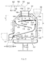
- FIG. 1 is a sectional view off essential parts of an apparatus for removing deposits
- FIG. 2 is a central longitudinal sectional view omitting an air vibration generating device 130 in FIG. 1
- FIG. 3 is a plan omitting the air vibration generating device 130 in FIG. 1.
- This apparatus for removing deposits comprises a removing apparatus main body 101 possessing a feed port 105 above a first porous member 104A stretched laterally in a main body case 101A formed tubularly in a decapitated pyramidal form, and a product outlet 111 in the lower part thereof, and an air vibration generating device 130 for supplying unidirectional pulsating air pulsating while flowing in one direction toward the first porous member 104A from above the porous member 104A, in which the removing apparatus main body 101 and the air vibration generating device 130 are installed separately from each other, and the pulsating air from the air vibration generating device 130 is supplied into the removing apparatus main body 101 through a waveguide 160.
- the porous member can be vibrated by the unidirectional pulsating air.
- first porous members 104A, second porous member 104B and third porous member 104Z possessing multiple tiny holes 103...103 smaller than the particle size of the powdered or granular materials to be treated as shown in FIG. 1.
- the porous members 104A, 104B, 104Z are inclined in the material feeding direction, and are disposed in different directions alternately from each other.
- the first porous member 104A is for directly receiving the materials supplied through the feed port 105, and is inclined by 2 to 3 degrees, and the second porous member 104B and third porous member 104Z are inclined about 15 degrees. But these angles are not limitative.
- the inclination angles of the porous members 104A, 104B, 104Z are defined smaller than the angle of repose for the materials to slide down, and are determined in consideration of the retention time for contact with the pulsating air for fluidizing the materials smoothly, the forward force for conveying the fluidized materials in the feed direction, the size of the main body case 101A, noise during deposit removal work, and other conditions.
- numerals 114, 115, 116 are mounting shafts of the porous members 104A, 104B, 104Z, and 117 and 118 are defining bars which prevent the first and second porous members 104A, 104B from oscillating toward the downward direction.
- Numeral 119 is an outlet opening edge of main body case 101A by which the third porous member 104Z is prevented to vibrate.
- the front end of the waveguide 160 is connected to a vibration wave feed tube 109 mounted on the upper opening 108 of the main body case 101A.
- a porous plate 112 having multiple tiny holes 113 smaller than the particle size of the materials m is suspended so that the materials m supplied onto the first porous member 104A from the hopper 122 may not be sucked in by the air source 140 of the air vibration generating device 130.
- the distance L between the lower end of the vibration wave feed tube 109 and the first porous member 104A should be as short as possible because the magnitude of the vibration wave may be smaller. According to the experiment by the present inventor, when the distance L is about 40 to 45 mm, the noise by sound wave was small and favorable results were obtained.
- the distance L is variable with the shape of the main body case 101A, such as height, width and depth, and is not limited to the mentioned figures.
- the air vibration generating device 130 is an intake port 142 of an air source 140 of suction type such as blower and a valve 150 which is an oscillating device are connected with a tube 141, and the valve 150 is connected with a communication port 110A formed on a lid 110 for covering the opening of the vibration wave feed tube 109 of the removing apparatus main body 101, the duct of the waveguide 160 is intermittently opened and closed by the valve 150, and unidirectional pulsating waves are supplied toward the first porous member 104A (second and third porous members 104B and 104Z) through the vibration wave feed tube 109.
- the waveform of the air vibration wave is corrugated in negative pressure state.
- a dish-shaped deposit takeout means 107 is detachably fitted by a tightening piece 125 such as punching lock. Deposits of the materials removed by pulsating waves through porous members 104A...104Z are collected in this deposit takeout means 107.
- the materials m being rid of deposits are discharged outside from a material outlet 111.
- Dust particles lower in specific gravity than the deposits are discharged to the air vibration generating device 130 through the vibration wave feed tube 109 and waveguide 160.
- an exhaust tube (not shown) may be branched off on the way of the waveguide 160 to collect dust from the exhaust tube.
- porous members 104A, 104B, 104Z are not limited to three stages as disclosed in this embodiment, but may be constructed in two stages, four stages or others as desired.
- unidirectional pulsating air moving in one direction i.e., in the direction of suction (the direction indicated by the arrow mark in Figure 1)
- the porous members jump up by turning upward with the air current and this jumping up of the porous members causes the materials supplied to the top face of the porous members to jump upward.
- the porous members drop with their own weight before the material does while the material is still suspended in the air. Then, when the material drops, the frequency of the puslating wave is already in the next period and the porous members jump up. The collision between the dropping materials and the jumping up porous members at that time powerfully separates and peels the deposits adhering to the materials.
- the apparatus for removing deposits of the invention In order to remove deposits from materials efficiently, by the apparatus for removing deposits of the invention, it is required to satisfy the three conditions: 1. particles of materials m should be fluidized on the surface of porous member by turning upside down without being broken, 2. the deposit removal rate from materials m should be high, and 3. the noise level by air vibration wave should be lower than the allowable limit.
- electrostatic deposits on the materials may be neutralized on the whole, and air vibration is applied at the same time, and hence the deposits may be removed effectively.
- This method and apparatus of removal may be applied, for example, in removal of deposits of semiconductor products or semifinished products in the semiconductor industry.
- the invention is intended to remove deposits by air vibrations, and by properly changing the air pressure or air flow rate, the deposit peeling force from materials may be properly changed, and in the case of coated materials such as sugar-coated tablets, the quality may be guaranteed by preventing mixture of dust while protecting the surface.
Landscapes
- Cleaning In General (AREA)
- Combined Means For Separation Of Solids (AREA)
Description
- The present invention relates to apparatus for removing deposits to be applicable widely in industries in which it is necessary to remove dusts or other deposits from powdered or granular materials such as tablets, remove foreign matter adhering on the surface of semiconductor products, or remove dusts or other deposits from other materials. The invention may be also applied as the apparatus for classifying by sifting powdered or granular materials.
- Hitherto, as the method for sifting powdered or granular materials capable of removing deposits from materials, the Japanese Patent Publication Sho. 52-10538 is known. This publication discloses what is shown in FIG. 5, which is designed to sift powdered or granular materials by using pulsating air.
- The constitution in FIG. 5 is explained below. An
exhaust port 501 and atakeout port 502 are provided in upper and lower parts of a hopper-shaped casing 500, and asieve mesh 503 is stretched horizontally in thecasing 500, and pulsating air or non-pulsating air flow is sent to amaterial layer 504 above thesieve mesh 503 from anair pipe 505 opened downward of thesieve mesh 503 to fluidize the powdered or granular materials on thesieve mesh 503, so that the materials of specified particle size may be sifted. That is, thetakeout port 502 communicates with a proper exhaust device or separating device in next step, for example, cyclone device, and the air is sucked out in the direction of arrow a, and therefore the powdered or granular materials on thesieve mesh 503 are fluidized by the vertical reciprocal air flow continuously as indicated by arrow b as cooperating action with pulsating air by theair pipe 505. - In short, in this prior art, by the cooperating action of the air flow from the
air pipe 505 toward thematerial layer 504 and the downward air flow from thetakeout port 502, the pulsating waves (arrow b) reciprocating vertically on thematerial layer 504 above thesieve mesh 503 act to effect classifying action. - Therefore, in the prior art, in order to fluidize the
material layer 504 on thesieve mesh 503 by the vertical reciprocal air flow b (plus [+] and minus [-] method), the air flow from theair pipe 505 must be actuated by a considerably large energy, and hence the noise increases. To suppress the noise, thecasing 500 must be put in a case made of soundproof wall such as concrete. It hence requires a special soundproof case, and it is not practical. - The invention is devised in order to solve these problems, and presents a apparatus capable of removing deposits from materials by applying air vibrations, operating practically at a low noise level.
- It is hence a primary object of the invention to present an apparatus for removing deposits adhering on materials by fluidizing the deposits to be removed with a pulsating air in one direction, without fluidizing with vertical reciprocating air flow as in the prior art, thereby requiring smaller energy, releasing less noise than in the prior art, and enhancing the practical value without damaging the materials themselves.
- It is another object of the present invention, to present an apparatus for removing deposits, wherein both the material and the porous members are made to vibrate because a plural number of porous members disposed laterally in stairs in opposite direction alternately in the main body case of cylindrical form are designed to vibrate with unidirectional pulsating air. This increases the impact force among the particles of the material and facilitates separation and peeling of the deposits adhering to the material, thus not only improving the deposit removing capacity but also ensuring uniform removal and preventing clogging of the porous members.
- It is another object of the present invention to provide an apparatus for removing deposits, wherein the inside of the empty compartment of the main body case is provided with a pulsating wave of suction air from above and the suction air acts on the entire area of the material on the porous members without producing any drift in itself thereby making it possible to remove deposits from the material more uniformly and effectively in combination with the vibrating action of the porous members and the material itself with unidirectional pulsating air.
- Moreover, since the present invention is designed to remove deposits from the material by means of pulsating wave of suction, it is another object of the present invention to provide an appartus for removing deposits wich does not cause any flying of dust nor require any sealing and reduces the number of parts as a result of the simple construction and absence of mechanical drive system and is easy to maintain.
- It is other object of the invention to present an apparatus for removing deposits efficiently, capable of freely adjusting the peeling force for removing deposits adhering on materials, by changing the waveform of pulsating waves in one direction to be supplied to the materials to be treated, and and treating flexibly depending on the state of deposits.
- It is another object of the invention to present an apparatus, capable of performing automatically in a series of operations from removal of deposits adhering on materials till discarding, by taking out the deposits removed from the materials by pulsating air in one direction from the main body of the apparatus for removing.
- It is a different object of the invention to present a apparatus for removing deposits, capable of treating if the materials being rid of deposits can be hardly conveyed efficiently in the discharge direction by the force of the pulsating air in one direction, that is, applying a force for advancing the materials on a porous material in the discharge direction, by tilting the porous material disposed in the main body of the apparatus for removing in a downward slope to the feed direction of material, or by vibrating.
- Other objects, features and benefits of the invention will be clarified and appreciated well in the following description.
- To achieve these objects, the apparatus of the invention presents an apparatus for removing deposits from materials comprising a main body case forming the main body of the removing apparatus; a plural number of porous members disposed laterally in stairs in opposite directions alternately in the main body case; a feed port for material provided on the main body case above the porous member at the top; a product outlet provided at a lower part of the main body case; and an air vibration generating device for feeding unidirectional pulsating air pulsating while flowing in one direction toward said porous members from above said porous members so that both said materials and said porous members are caused to vibrate under action of said pulsating air; said air vibration generating device comprising an air source of a suction type, an oscillating device and a wave guide with a lower end of said wave guide communicating with an opening at a top of the main body so as to absorb an inside of the empty compartment of the main body case with a pulsating wave of suction air from above.
- The unidirectional pulsating wave by the air vibration generating device is obtained chiefly by vibrating the sound waves in low frequency or medium frequency band, including inaudible sound waves with air, nitrogen or other gas, and its waveform is generally obtained as pulse wave or sine wave, but the waveforms of the invention may be freely varied as far as belonging the minus (-) region, supposing the upper part from the baseline (atmospheric pressure) to be the plus (+) region and the lower part as the minus (-) region.
- The air vibration generating device comprises an air source for generating air or gas such as ring blower, roots blower and vacuum pump, an oscillating device for vibrating the air from the air source, and a waveguide for leading the air vibration from the oscillating device to the removing apparatus main body. However, the air vibration generating device is not limited to this constitution alone, and for example, the suction port or exhaust port of the air source such as blower is connected to the removing apparatus main body with the waveguide, and a valve is provided on the way of the waveguide, and the duct of the waveguide is opened and closed intermittently by this valve, thereby feeding the unidirectional pulsating air toward the porous meter in the removing apparatus main body. Or, by a reciprocating air compressor and a pressure air changeover device, air vibrations may be generated, or it may be composed of air source and rotor type changeover valve, and any other arbitrary constitutions may be possible.
- The air source is the suction type may be employed, and the air vibration waves are repeated only in the minus region toward the porous member.
- In the apparatus the waveforms of the air pulsating wave supplied from the air vibration generating device are variable.
- The material supplied on the porous member is turned upside-down and fluidized by the unidirectional pulsating air, and classified into desired particle size, that is, the deposits and products are separated. At this time, it may be hard to convey the products being rid of deposits efficiently into the discharge direction by the force of the unidirectional pulsating air. Considering such situation, the porous member may be inclined in a down slope to the feed direction of material, or the porous member may be vibrated, and thus a force for advancing the material on the porous member is provided.
- The removing apparatus main body is furnished with deposit takeout means.
- The gas for applying gas vibration is mainly air in the invention, but not limited to air alone, other gases such as ionized air (for example, ozone) and inert gas may be included.
- Figure 1 is a longitudinal sectional view of essential parts in a preferred embodiment of the invention;
- Figure 2 is a central longitudinal sectional view omitting an air vibration generating device in FIG. 1;
- Figure 3 is a plan omitting the air vibration generating device in FIG. 1;
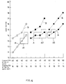
- Figure 4 is a graph showing the relation between frequency of air source and low frequency and noise level; and
- Figure 5 is a longitudinal sectional view of a prior art.
- An optimum embodiment of the invention is shown in FIGS. 1 to 3.
- FIG. 1 is a sectional view off essential parts of an apparatus for removing deposits, FIG. 2 is a central longitudinal sectional view omitting an air vibration generating
device 130 in FIG. 1, and FIG. 3 is a plan omitting the air vibration generatingdevice 130 in FIG. 1. This apparatus for removing deposits comprises a removing apparatusmain body 101 possessing afeed port 105 above a firstporous member 104A stretched laterally in amain body case 101A formed tubularly in a decapitated pyramidal form, and aproduct outlet 111 in the lower part thereof, and an air vibration generatingdevice 130 for supplying unidirectional pulsating air pulsating while flowing in one direction toward the firstporous member 104A from above theporous member 104A, in which the removing apparatusmain body 101 and the air vibration generatingdevice 130 are installed separately from each other, and the pulsating air from the air vibration generatingdevice 130 is supplied into the removing apparatusmain body 101 through awaveguide 160. - The porous member can be vibrated by the unidirectional pulsating air.
- In an
empty compartment 102 of themain body case 101A there are provided in stairs the firstporous members 104A, secondporous member 104B and thirdporous member 104Z possessing multipletiny holes 103...103 smaller than the particle size of the powdered or granular materials to be treated as shown in FIG. 1. - The
porous members porous member 104A is for directly receiving the materials supplied through thefeed port 105, and is inclined by 2 to 3 degrees, and the secondporous member 104B and thirdporous member 104Z are inclined about 15 degrees. But these angles are not limitative. The inclination angles of theporous members main body case 101A, noise during deposit removal work, and other conditions. - In FIG. 1,
numerals porous members porous members main body case 101A by which the thirdporous member 104Z is prevented to vibrate. The front end of thewaveguide 160 is connected to a vibrationwave feed tube 109 mounted on theupper opening 108 of themain body case 101A. At the lower end of the vibrationwave feed tube 109, aporous plate 112 having multipletiny holes 113 smaller than the particle size of the materials m is suspended so that the materials m supplied onto the firstporous member 104A from thehopper 122 may not be sucked in by theair source 140 of the airvibration generating device 130. - The distance L between the lower end of the vibration
wave feed tube 109 and the firstporous member 104A should be as short as possible because the magnitude of the vibration wave may be smaller. According to the experiment by the present inventor, when the distance L is about 40 to 45 mm, the noise by sound wave was small and favorable results were obtained. Anyway, the distance L is variable with the shape of themain body case 101A, such as height, width and depth, and is not limited to the mentioned figures. - The air
vibration generating device 130 is anintake port 142 of anair source 140 of suction type such as blower and avalve 150 which is an oscillating device are connected with atube 141, and thevalve 150 is connected with acommunication port 110A formed on alid 110 for covering the opening of the vibrationwave feed tube 109 of the removing apparatusmain body 101, the duct of thewaveguide 160 is intermittently opened and closed by thevalve 150, and unidirectional pulsating waves are supplied toward the firstporous member 104A (second and thirdporous members wave feed tube 109. In this case, the waveform of the air vibration wave is corrugated in negative pressure state. - In the lower part of the
empty compartment 102 in themain body case 101A, a dish-shaped deposit takeout means 107 is detachably fitted by a tighteningpiece 125 such as punching lock. Deposits of the materials removed by pulsating waves throughporous members 104A...104Z are collected in this deposit takeout means 107. - On the other hand, the materials m being rid of deposits are discharged outside from a
material outlet 111. - Dust particles lower in specific gravity than the deposits are discharged to the air vibration generating
device 130 through the vibrationwave feed tube 109 andwaveguide 160. In this case, an exhaust tube (not shown) may be branched off on the way of thewaveguide 160 to collect dust from the exhaust tube. - Meanwhile, the
porous members - The reason why the porous members are made to vibrate with unidirectional pulsating air in the present invention will be exlained hereinafter based upon the accompanying drawings.
- Namely, unidirectional pulsating air moving in one direction, i.e., in the direction of suction (the direction indicated by the arrow mark in Figure 1), is produced with the action of the
air source 140 of a suction type and thevalve 150 . During the period in which the pulsating air current flows upward, the porous members jump up by turning upward with the air current and this jumping up of the porous members causes the materials supplied to the top face of the porous members to jump upward. Next, during the period in which the flow of the pulsating fluid comes to a standstill, the porous members drop with their own weight before the material does while the material is still suspended in the air. Then, when the material drops, the frequency of the puslating wave is already in the next period and the porous members jump up. The collision between the dropping materials and the jumping up porous members at that time powerfully separates and peels the deposits adhering to the materials. - In order to remove deposits from materials efficiently, by the apparatus for removing deposits of the invention, it is required to satisfy the three conditions: 1. particles of materials m should be fluidized on the surface of porous member by turning upside down without being broken, 2. the deposit removal rate from materials m should be high, and 3. the noise level by air vibration wave should be lower than the allowable limit.
- On the basis of these conditions, the inventor experimented apparatus A and apparatus B, and obtained results as shown in FIG. 4.
- (1) Apparatus A (FIGS. 1 through 3)
Height h is 168 mm, width w is 170 mm, depth d is 100 mm, and L is 45 mm.
Apparatus B
Width w and depth d are same as in apparatus A, L is 90 mm, and height h is 250 mm. - (2) Tablets were prepared as materials from which deposits are removed.
- (3) In FIG. 4, using a ring blower as the
air source 140, the frequency (Hz) of theair source 140 is plotted in the upper part of the axis of abscissas and the frequency (Hz) of low frequency waves (sound waves) in the lower part, and the noise level (db) is plotted on the axis of ordinates. Polygonal line A in FIG. 4 represents apparatus A of the invention, and polygonal line B denotes apparatus B, and blocks A1, A2, A3 satisfy the three conditions 1, 2, 3, showing the regions proved to be practical as the apparatus for removing deposits from materials. Polygonal B is found to be impracticable, not satisfying at least one of the three conditions 1, 2, 3, that is, the tablets cannot be fluidized, the deposit removal rate is low, or the noise level is over 75 db which is the allowable limit. - Incidentally, when composed so that the ionized air is vibrated and applied on the material surface, electrostatic deposits on the materials may be neutralized on the whole, and air vibration is applied at the same time, and hence the deposits may be removed effectively. This method and apparatus of removal may be applied, for example, in removal of deposits of semiconductor products or semifinished products in the semiconductor industry.
- The invention is intended to remove deposits by air vibrations, and by properly changing the air pressure or air flow rate, the deposit peeling force from materials may be properly changed, and in the case of coated materials such as sugar-coated tablets, the quality may be guaranteed by preventing mixture of dust while protecting the surface.
Claims (4)
- An apparatus for removing deposits from materials comprising:
a main body case (101A) forming the main body (101) of the removing apparatus; a plural number of porous members (104A···104Z) disposed laterally in stairs in opposite directions alternately in the main body case (101A) ; a feed port (105) for material provided on the main body case (101A) above the porous member (104A) at the top; a product outlet (111) provided at a lower part of the main body case (101A) ; and an air vibration generating device (130) for feeding unidirectional pulsating air pulsating while flowing in one direction toward said porous members (104A···104Z) from above said porous members so that both said materials and said porous members are caused to vibrate under action of said pulsating air; said air vibration generating device (130) comprising an air source (140) of a suction type, an oscillating device (150) and a wave guide (160) with a lower end of said wave guide communicating with an opening (108) at a top of the main body so as to absorb an inside of the empty compartment (102) of the main body case (101A) with a pulsating wave of suction air from above. - An apparatus as claimed in claim 1 ,wherein the porous member (104A ··· 104Z) is inclined downwardly in the feed direction of material (m).
- An apparatus as claimed in claims 1 or 2 , wherein the porous member (104A···104Z) is designed to vibrate.
- An apparatus as claimed in any of claims 1 to 3 , wherein a deposit takeout means (107) is provided at the lower part of the main body of removing apparatus.
Applications Claiming Priority (4)
| Application Number | Priority Date | Filing Date | Title |
|---|---|---|---|
| JP16523492 | 1992-05-12 | ||
| JP165234/92 | 1992-05-12 | ||
| JP5144191A JPH06262150A (en) | 1992-05-12 | 1993-05-10 | Method and device for removing depositions |
| JP144191/93 | 1993-05-10 |
Publications (2)
| Publication Number | Publication Date |
|---|---|
| EP0572140A1 EP0572140A1 (en) | 1993-12-01 |
| EP0572140B1 true EP0572140B1 (en) | 1997-04-09 |
Family
ID=26475688
Family Applications (1)
| Application Number | Title | Priority Date | Filing Date |
|---|---|---|---|
| EP93303678A Expired - Lifetime EP0572140B1 (en) | 1992-05-12 | 1993-05-12 | Apparatus for removing deposits adhering to surfaces by pulsed air |
Country Status (4)
| Country | Link |
|---|---|
| US (1) | US5504972A (en) |
| EP (1) | EP0572140B1 (en) |
| JP (1) | JPH06262150A (en) |
| DE (1) | DE69309538T2 (en) |
Families Citing this family (29)
| Publication number | Priority date | Publication date | Assignee | Title |
|---|---|---|---|---|
| JP3445330B2 (en) * | 1993-11-15 | 2003-09-08 | 株式会社松井製作所 | Adhered matter removing apparatus and attached matter removing method |
| DE4432503C2 (en) * | 1994-09-13 | 1998-09-03 | Behr Industrietech Gmbh & Co | Process for cleaning the hollow body of a heat exchanger and device for carrying out the process |
| JPH08165021A (en) * | 1994-12-13 | 1996-06-25 | Matsui Mfg Co | Suction and transportation method of powdery granular material using pulsating air vibration wave and its apparatus |
| JP3620890B2 (en) * | 1995-03-22 | 2005-02-16 | 日新電子工業株式会社 | Foreign matter incinerator in solid matter |
| US5839455A (en) * | 1995-04-13 | 1998-11-24 | Texas Instruments Incorporated | Enhanced high pressure cleansing system for wafer handling implements |
| JP3673306B2 (en) * | 1995-08-24 | 2005-07-20 | バブコック日立株式会社 | Tube cleaning device and boiler device |
| JP3673307B2 (en) * | 1995-08-25 | 2005-07-20 | バブコック日立株式会社 | Tube cleaning device |
| JPH09221229A (en) * | 1996-02-16 | 1997-08-26 | Matsui Mfg Co | Blockage prevention device in conduit |
| JP3242326B2 (en) * | 1996-08-06 | 2001-12-25 | 成司 町田 | Dust removal device |
| CN1093008C (en) * | 1996-10-21 | 2002-10-23 | 钴碳化钨硬质合金公司 | Powder metallurgy method and device |
| BE1011863A4 (en) * | 1998-04-06 | 2000-02-01 | Quertinmont Jean | Suction device and suction process |
| JP4514986B2 (en) * | 2001-05-11 | 2010-07-28 | 本田技研工業株式会社 | Laminated glass separation and recovery equipment |
| US7096529B2 (en) * | 2004-12-06 | 2006-08-29 | Sun Automation Inc. | Box finishing machine with cleaning apparatus and method |
| JP4634158B2 (en) * | 2005-01-20 | 2011-02-16 | 株式会社テクノ菱和 | Powder sieve device with static eliminator |
| JP4767770B2 (en) * | 2006-06-27 | 2011-09-07 | 池上通信機株式会社 | Tablet adhering powder removal device |
| WO2009043137A1 (en) * | 2007-10-02 | 2009-04-09 | Cleancount Incorporated | A self cleaning pill counting device, and cleaning method |
| WO2008040124A1 (en) | 2006-10-02 | 2008-04-10 | 2338296 Nova Scotia Limited (Doing Business As Tramar Products) | A self cleaning pill counting device, and cleaning method |
| US20080128002A1 (en) * | 2006-12-04 | 2008-06-05 | Jeffs Dawnette E | Capsule de-duster and powder reclamation apparatus |
| CN102327188B (en) | 2008-09-18 | 2015-04-01 | 株式会社汤山制作所 | Tablet feeder |
| CN102341307B (en) * | 2009-03-05 | 2014-12-17 | 株式会社汤山制作所 | Powder removing device for tablet feeder |
| US8695156B2 (en) * | 2010-02-10 | 2014-04-15 | Jeffrey S. Marshall | Aeroacoustic duster |
| WO2011108448A1 (en) * | 2010-03-01 | 2011-09-09 | 株式会社湯山製作所 | Powder removal device of medicine dispenser |
| JP6011327B2 (en) * | 2012-12-27 | 2016-10-19 | 新日鐵住金株式会社 | Vibrating sieve device and cleaning method thereof |
| DE102014103544B4 (en) * | 2014-03-14 | 2015-10-01 | Jäger Innovation UG | Extraction and cleaning device |
| DE102014215404A1 (en) * | 2014-08-05 | 2016-02-11 | Robert Bosch Gmbh | Method and device for processing a semiconductor material |
| KR101701907B1 (en) * | 2014-12-04 | 2017-02-03 | 삼성중공업 주식회사 | Chain locker for anchoring system |
| CN108787455A (en) * | 2018-07-25 | 2018-11-13 | 软控股份有限公司 | The bugduster of oscillatory type |
| JP6855552B2 (en) * | 2019-10-31 | 2021-04-07 | 荏原環境プラント株式会社 | Wind classifier |
| FR3135996B1 (en) * | 2022-05-27 | 2024-07-26 | Denis Joandel | Process for preparing aggregates intended to form a permeable floor covering and device for its implementation |
Family Cites Families (16)
| Publication number | Priority date | Publication date | Assignee | Title |
|---|---|---|---|---|
| US693455A (en) * | 1901-03-11 | 1902-02-18 | John Charles William Stanley | Drier for cotton or other materials. |
| US2200472A (en) * | 1938-06-29 | 1940-05-14 | Schering Corp | Granular material separating machine |
| US2425984A (en) * | 1942-09-26 | 1947-08-19 | Blackman Stanley | Method for cleaning capsules and the like |
| US2512422A (en) * | 1946-11-21 | 1950-06-20 | James H Fletcher | Pneumatic coal cleaner |
| US2617137A (en) * | 1948-03-22 | 1952-11-11 | Bodnar Alexander | Apparatus for dusting capsules |
| US2903132A (en) * | 1955-05-07 | 1959-09-08 | Berry Paul | Apparatus for sorting solid products by density |
| US2918691A (en) * | 1957-05-06 | 1959-12-29 | Lilly Co Eli | Capsule cleaning device |
| US3096532A (en) * | 1960-05-05 | 1963-07-09 | Stokes F J Corp | Tablet duster |
| US3166004A (en) * | 1960-12-28 | 1965-01-19 | Dca Food Ind | Flour removal |
| CH522451A (en) * | 1970-04-29 | 1972-06-30 | Buehler Ag Geb | Method and device for treating granular bulk material |
| DE2657565C3 (en) * | 1976-12-18 | 1980-10-02 | Truetzschler Gmbh & Co Kg, 4050 Moenchengladbach | Device for cleaning and dedusting textile fiber flocks |
| SE8107374L (en) * | 1981-12-09 | 1983-06-10 | Kelva Ab | web cleaners |
| SU1297944A1 (en) * | 1985-02-14 | 1987-03-23 | Всесоюзный Научно-Исследовательский Институт Льна | Method of separation of granular materials |
| US4677704A (en) * | 1986-04-22 | 1987-07-07 | Huggins Richard A | Cleaning system for static charged semiconductor wafer surface |
| SE8902335L (en) * | 1989-06-28 | 1990-12-29 | Flaekt Ab | PROCEDURE AND DEVICE FOR CLEANING WHEELS |
| WO1991012629A1 (en) * | 1990-02-16 | 1991-08-22 | Edward Bok | Improved installation for wafer transfer and processing |
-
1993
- 1993-05-10 JP JP5144191A patent/JPH06262150A/en active Pending
- 1993-05-12 US US08/060,724 patent/US5504972A/en not_active Expired - Fee Related
- 1993-05-12 EP EP93303678A patent/EP0572140B1/en not_active Expired - Lifetime
- 1993-05-12 DE DE69309538T patent/DE69309538T2/en not_active Expired - Fee Related
Also Published As
| Publication number | Publication date |
|---|---|
| EP0572140A1 (en) | 1993-12-01 |
| DE69309538D1 (en) | 1997-05-15 |
| US5504972A (en) | 1996-04-09 |
| DE69309538T2 (en) | 1997-07-24 |
| JPH06262150A (en) | 1994-09-20 |
Similar Documents
| Publication | Publication Date | Title |
|---|---|---|
| US5504972A (en) | Method and apparatus for removing deposits adhering on materials | |
| US5042724A (en) | Fluorescent tube crusher with particulate separation and recovery | |
| US8813966B2 (en) | Pneumatic vacuum separation plant for bulk materials | |
| EP1102642B1 (en) | Material classifying apparatus | |
| US5103981A (en) | Particle separator/classification mechanism | |
| US2512422A (en) | Pneumatic coal cleaner | |
| CA1215683A (en) | Inclined vibrated screen with pneumatic cyclonic flow input and pressure relief means | |
| JPH084701B2 (en) | Dust collector | |
| EP0316622B1 (en) | Method and apparatus for elutriation of shaped particles of polymeric resin | |
| JP7005627B2 (en) | Separator for polysilicon | |
| US20220362807A1 (en) | Air wash abrasive and contaminants separator apparatus | |
| US4946044A (en) | Aeration separator | |
| JP6603482B2 (en) | Abrasive classifier | |
| JP4110591B2 (en) | Vibrating feeder | |
| CN112638556A (en) | Air flushing device and system for flushing containers | |
| GB2059810A (en) | Process and installation for removing dust from particles | |
| JP3013054B2 (en) | Blast equipment | |
| JPH10249120A (en) | Gravitational dust collector | |
| JPS6219208B2 (en) | ||
| WO1989004802A2 (en) | Conveying apparatus and separation apparatus | |
| GB2305375A (en) | A Washing Plant | |
| JP2000218237A (en) | Sorting device for waste | |
| RU2209691C2 (en) | Apparatus for dedusting loose, namely mineral materials | |
| JPH04132999A (en) | Decontamination of radioactive waste | |
| WO2004007053A2 (en) | Device for the filtration and collection of microparticles in a gaseous environment |
Legal Events
| Date | Code | Title | Description |
|---|---|---|---|
| PUAI | Public reference made under article 153(3) epc to a published international application that has entered the european phase |
Free format text: ORIGINAL CODE: 0009012 |
|
| AK | Designated contracting states |
Kind code of ref document: A1 Designated state(s): DE FR GB IT |
|
| 17P | Request for examination filed |
Effective date: 19940526 |
|
| 17Q | First examination report despatched |
Effective date: 19950711 |
|
| GRAG | Despatch of communication of intention to grant |
Free format text: ORIGINAL CODE: EPIDOS AGRA |
|
| GRAH | Despatch of communication of intention to grant a patent |
Free format text: ORIGINAL CODE: EPIDOS IGRA |
|
| GRAH | Despatch of communication of intention to grant a patent |
Free format text: ORIGINAL CODE: EPIDOS IGRA |
|
| GRAA | (expected) grant |
Free format text: ORIGINAL CODE: 0009210 |
|
| ITF | It: translation for a ep patent filed | ||
| AK | Designated contracting states |
Kind code of ref document: B1 Designated state(s): DE FR GB IT |
|
| REF | Corresponds to: |
Ref document number: 69309538 Country of ref document: DE Date of ref document: 19970515 |
|
| ET | Fr: translation filed | ||
| PLBE | No opposition filed within time limit |
Free format text: ORIGINAL CODE: 0009261 |
|
| STAA | Information on the status of an ep patent application or granted ep patent |
Free format text: STATUS: NO OPPOSITION FILED WITHIN TIME LIMIT |
|
| 26N | No opposition filed | ||
| REG | Reference to a national code |
Ref country code: GB Ref legal event code: IF02 |
|
| PGFP | Annual fee paid to national office [announced via postgrant information from national office to epo] |
Ref country code: DE Payment date: 20070510 Year of fee payment: 15 |
|
| PGFP | Annual fee paid to national office [announced via postgrant information from national office to epo] |
Ref country code: GB Payment date: 20070509 Year of fee payment: 15 |
|
| PGFP | Annual fee paid to national office [announced via postgrant information from national office to epo] |
Ref country code: IT Payment date: 20070525 Year of fee payment: 15 |
|
| PGFP | Annual fee paid to national office [announced via postgrant information from national office to epo] |
Ref country code: FR Payment date: 20070510 Year of fee payment: 15 |
|
| GBPC | Gb: european patent ceased through non-payment of renewal fee |
Effective date: 20080512 |
|
| REG | Reference to a national code |
Ref country code: FR Ref legal event code: ST Effective date: 20090119 |
|
| PG25 | Lapsed in a contracting state [announced via postgrant information from national office to epo] |
Ref country code: FR Free format text: LAPSE BECAUSE OF NON-PAYMENT OF DUE FEES Effective date: 20080602 Ref country code: DE Free format text: LAPSE BECAUSE OF NON-PAYMENT OF DUE FEES Effective date: 20081202 |
|
| PG25 | Lapsed in a contracting state [announced via postgrant information from national office to epo] |
Ref country code: GB Free format text: LAPSE BECAUSE OF NON-PAYMENT OF DUE FEES Effective date: 20080512 |
|
| PG25 | Lapsed in a contracting state [announced via postgrant information from national office to epo] |
Ref country code: IT Free format text: LAPSE BECAUSE OF NON-PAYMENT OF DUE FEES Effective date: 20080512 |